Buhler SDW 800/1000 User manual

Bühler AG
CH-9240 Uzwil/Switzerland
Phone +41 71 955 11 11
Fax +41 71 955 33 79
www.buhlergroup.com
Operating Instructions
Three-roll Mill
SDW 800/1000
SDW 800/1000-Ex
Spare Parts Catalogue, see 80394 SDW_80357-1-en-0703

2Three-roll Mill
SDW 800/1000 (-Ex), 80357-1-en-0703 © Copyright 2007 Bühler AG

Three-roll Mill Introduction 3
Introduction
These operating instructions (translation) include basic information on the design,
the installation, start-up, operation and maintenance of the machine.
The following separate documentation is integral part of the operating instructions:
– Spare Parts Catalogue, see 80394
For comprehension of these operating instructions
Important notes are distinguished as follows:
DANGER!
Hazards which can result in physical injuries or in death.
CAUTION!
Hazards which can result in operation failures or machine damage.
Note:
Important information or instructions.
•Procedural instructions are marked by point of eyecatcher.
If the machine is certified on the Nameplate with the appropriate ATEX
designation for operation in the explosion-dangerous area, the information
and instructions marked by are condition for the perpetuation of the
ignition protection. Therefore they must be absolutely kept.
© Copyright 2007 Bühler AG SDW 800/1000 (-Ex), 80357-1-en-0703

4 Introduction Three-roll Mill
SDW 800/1000 (-Ex), 80357-1-en-0703 © Copyright 2007 Bühler AG

Three-roll Mill Table of contents 5
Table of contents
1Safety ............................................................................................................ 9
1.1 General .......................................................................................................................... 9
1.2 In the explosion-dangerous area ................................................................................. 10
During maintenance works.............................................................................. 10
2Description ................................................................................................. 11
2.1 Identification................................................................................................................. 11
2.1.1 Nameplate....................................................................................................... 11
2.1.2 Type code........................................................................................................ 11
2.2 Use in accordance with intended purpose................................................................... 12
2.3 Design and function ..................................................................................................... 13
2.3.1 Three-roll Mill .................................................................................................. 13
2.3.2 Roll positions................................................................................................... 14
2.3.3 Cambered chilled-iron rolls ............................................................................. 16
2.3.4 Hydraulic system............................................................................................. 17
Pump unit ........................................................................................................ 18
Hydraulics (standard) ...................................................................................... 18
Options............................................................................................................ 19
2.3.5 Roll drive ......................................................................................................... 20
2.3.6 Roll cooling...................................................................................................... 21
Open flow-through cooling .............................................................................. 21
Open flow-through cooling with cooling water tank ........................................ 23
2.3.7 Hydraulic oil cooling ........................................................................................ 25
2.3.8 Product trough................................................................................................. 26
Hopper plates.................................................................................................. 26
2.3.9 Scraper............................................................................................................ 27
2.3.10 Safety bar........................................................................................................ 28
2.3.11 Level monitoring (option)................................................................................. 29
Design without certification for explosion-dangerous areas ........................... 29
Models certified for the explosion-dangerous area......................................... 29
2.3.12 Filling hydraulic system (option)...................................................................... 30
2.3.13 Roll nip setting (option) ................................................................................... 30
2.3.14 Bucket tilting device (option) ........................................................................... 31
Loading capacity ............................................................................................. 32
2.3.15 Protective cover (option) ................................................................................. 32
2.4 Technical data.............................................................................................................. 33
2.4.1 Weight ............................................................................................................. 33
2.4.2 Dimensions...................................................................................................... 33
Machine........................................................................................................... 33
Control cabinet ................................................................................................ 33
2.4.3 Power rating .................................................................................................... 33
Ratings ............................................................................................................ 33
Motor power .................................................................................................... 34
2.4.4 Roll cooling...................................................................................................... 34
2.4.5 Hydraulic system............................................................................................. 34
2.4.6 Noise data ....................................................................................................... 34
© Copyright 2007 Bühler AG SDW 800/1000 (-Ex), 80357-1-en-0703

6 Table of contents Three-roll Mill
2.5 Operating materials...................................................................................................... 35
2.5.1 Cooling water................................................................................................... 35
2.5.2 Hydraulic oil ..................................................................................................... 35
2.5.3 Gear oil ............................................................................................................ 35
2.5.4 For maintenance work..................................................................................... 35
2.6 Specific line pressure ................................................................................................... 36
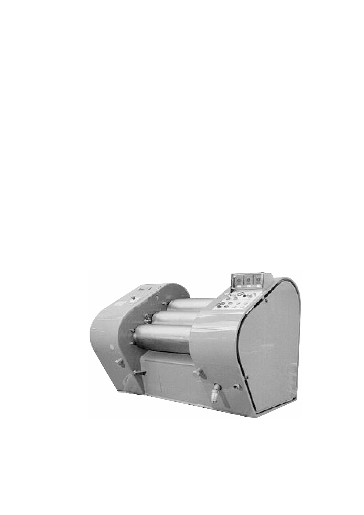
2.7 Dimension drawings..................................................................................................... 37
3Transport..................................................................................................... 38
3.1 General......................................................................................................................... 38
3.2 Storage......................................................................................................................... 38
3.3 Suspension on the crane ............................................................................................. 39
4Installation................................................................................................... 40
4.1 General......................................................................................................................... 40
4.2 Local conditions............................................................................................................ 40
Ambient conditions .......................................................................................... 40
4.3 Erection ........................................................................................................................ 40
4.3.1 Installation procedure ...................................................................................... 41
4.4 Electrical installation..................................................................................................... 42
4.4.1 Connecting to the power supply...................................................................... 42
Connecting the control cabinet........................................................................ 42
4.4.2 Earthing ........................................................................................................... 43
4.5 Installation of supply lines ............................................................................................ 43
4.5.1 Product lines.................................................................................................... 43
4.5.2 Cooling water lines .......................................................................................... 43
5Start-up........................................................................................................ 44
5.1 General......................................................................................................................... 44
5.2 Pre-operational inspections.......................................................................................... 45
5.3 Settings ........................................................................................................................ 46
5.3.1 Roll cooling setting .......................................................................................... 46
5.3.2 Filling in hydraulic oil and adjusting operating pressure.................................. 47
5.3.3 Aligning the rolls .............................................................................................. 48
5.3.4 Setting counter-pressure, hopper plate and scraper knife contact pressure .. 50
5.3.5 Inserting and fixing the scraper and setting it.................................................. 51
5.3.6 Level monitoring (option)................................................................................. 53
Without certification for the explosion-dangerous area................................... 53
Certified for the explosion-dangerous area ..................................................... 54
5.3.7 Calibrating the position indicator (option)........................................................ 57
5.3.8 Filling hydraulic system (option) ...................................................................... 58
5.3.9 Tightening the V-belts ..................................................................................... 59
5.3.10 Bucket tilting device (Option)........................................................................... 59
5.3.11 Adjusting of minimum roll nip (option) ............................................................. 60
5.4 Inspection of functions.................................................................................................. 61
5.4.1 Inspection of machine functions...................................................................... 62
Direction of rotation of the hydraulic pump motor ........................................... 62
Direction of rotation of the rolls........................................................................ 62
SDW 800/1000 (-Ex), 80357-1-en-0703 © Copyright 2007 Bühler AG

Three-roll Mill Table of contents 7
5.4.2 Checking the safety functions ......................................................................... 62
Emergency stop .............................................................................................. 62
Safety bar........................................................................................................ 63
5.5 Checking EU conformity .............................................................................................. 64
Check list for establishing EU conformity........................................................ 64
6Operation .................................................................................................... 66
6.1 General ........................................................................................................................ 66
6.2 Control panel................................................................................................................ 68
Functions......................................................................................................... 69
6.3 Operation ..................................................................................................................... 70
6.3.1 Prepare the start ............................................................................................. 70
6.3.2 Starting the machine ....................................................................................... 70
6.3.3 Machine turning off.......................................................................................... 71
6.3.4 Emergency stop .............................................................................................. 71
Emergency stop button ................................................................................... 71
Restart after emergency stop.......................................................................... 71
6.4 Roll nip setting (option) ................................................................................................ 72
6.5 Instructions for operation ............................................................................................. 73
6.5.1 “Sifting”............................................................................................................ 73
6.5.2 Process parameters ........................................................................................ 74
Influence of roll contact pressure and roll temperature................................... 74
6.6 Cleaning ....................................................................................................................... 75
6.6.1 Cleaning the machine ..................................................................................... 75
6.6.2 Cleaning of the rolls ........................................................................................ 75
Cleaning the first roll ....................................................................................... 77
Cleaning the second and third roll .................................................................. 78
6.7 Faults and troubleshooting........................................................................................... 79
7Maintenance ............................................................................................... 81
7.1 General ........................................................................................................................ 81
7.2 Maintenance and lubrication chart............................................................................... 83
7.3 Maintenance work........................................................................................................ 86
7.3.1 Hopper plate maintenance .............................................................................. 86
7.3.2 Cleaning water filter ........................................................................................ 86
7.4 Spare and wear parts................................................................................................... 87
7.5 Disposal ....................................................................................................................... 87
8After-sales service ..................................................................................... 88
Address for the after-sales service and the spare parts sale.......................... 88
© Copyright 2007 Bühler AG SDW 800/1000 (-Ex), 80357-1-en-0703

8 Table of contents Three-roll Mill
SDW 800/1000 (-Ex), 80357-1-en-0703 © Copyright 2007 Bühler AG

Three-roll Mill Safety 9
1 Safety
1.1 General
The machine is fitted with protection and safety devices in compliance with the
recognized safety engineering principles. Improper use of the machine may entail
dangers to the health and life of persons, or may cause damage to property.
These operating instructions must be kept close to the machine and be visible
anytime.
The machine must only be operated in compliance with all instructions and
prescriptions of these operating instructions.
•Pay special attention to the following danger areas:
– Danger of getting caught in nip:
Never reach into the nip or insert any object (such as spatula).
Do not wear thick protective gloves, which impede the capacity of tactile
sensation of your fingers.
Do not wear long, wide sleeves. The sleeves may get caught between
the rolls.
– If the machine is equipped with a protective cover (option), it must be
operated only with installed protective cover.
– For cleaning the rolls, insert the safety bar and fasten it, see
sect. 2.3.10.
– When cleaning, replacing the scraper knife or unfolding the apron,
always put on the scraper knife disassembly device, see sect. 5.3.5,
Fig. 5.10.
– When working in any of the machine’s danger areas, turn the all-pole
disconnecting lockable safety switch to “0” and secure against turning
on.
– When working on the electrical controller or on electrical components,
set the main switch on the control cabinet to “0” and lock it (key with
personnel).
•
•
•
•
•
•
•
•
•
In case of a danger of explosion, follow all the decisive safety instructions.
See sect. 2.2 “Use in accordance with intended purpose”.
Keep clean and do not remove or cover any warning and instruction signs.
Replace any damaged warning and instruction signs with new ones.
Do not remove or cover any designation numbers on electric wires.
Only lift the machine at the indicated suspension points, see chap. 3.
Do not walk or wait under suspended loads.
Only start-up and operate the machine when the protection devices are
intact and the safety equipment is operational, see sect. 5.1 and sect. 5.5.
Maintenance and cleaning work must be carried out only when the machine
is out of operation (no motion of the machine), see chap. 7.
Turn the all-pole disconnecting lockable safety switch to “0” and secure
against turning on.
Before operation of the machine make sure about function and operation of
the emergency stop switch, see sect. 6.3.4 “Emergency stop”.
Upon actuation of the emergency stop button, the main motor gets switched
off immediately.
The hydraulic pump remains in operation and must be switched off with the
push button “Hydraulic pump OFF”.
Always wear protective glasses during operation and maintenance of the
machine.
© Copyright 2007 Bühler AG SDW 800/1000 (-Ex), 80357-1-en-0703

10 Safety Three-roll Mill
1.2 In the explosion-dangerous area
•
•
In the explosion-dangerous area the machine must only be operated
according to its permission. The certification can be seen from the ATEX
designation on the Nameplate, see sect. 2.1 “Identification”.
The information and instructions marked with in these operating
instructions are indispensable for maintaining the ignition protection and thus
the certification for the indicated area. Therefore they must be observed
without fail.
During operation, the machine must be monitored in a way that the operating
personnel can react to operating failures.
Immediately stop the machine in the event of unusual running noise.
The installation and the product container must be in compliance with the
ATEX 95 directive.
Only operate the roll mill with the approved products, see sect. 2.2 “Use in
accordance with intended purpose”.
Only operate the roll mill with product.
When running the machine empty, observe the product inflow closely.
If there are foreign objects present, immediately switch off the machine.
Only use cleaning agents up to temperature class T3 in conformity with the
permission of the machine for the explosion-dangerous area, see sect. 2.1
“Identification”.
During maintenance works
•Only personnel who are authorised by the operator in accordance with their
safety instructions, must carry out maintenance work.
In the explosion-dangerous area, correct maintenance is the prerequisite for
maintaining the ignition protection.
Only use cleaning agents up to temperature class T3 in conformity with the
permission of the machine for the explosion-dangerous area, see sect. 2.1
“Identification”.
During all maintenance and cleaning work, avoid the build-up of ignitable
solvent fumes.
Do not stir up dust. Avoid dust settling.
In the proximity of combustible materials, do not carry out any welding or
emery works.
To maintain the ignition protection only use original spare parts, see
separate spare parts catalogue (80394).
Ensure that the machine is correctly earthed again after maintenance works.
(The equipotential bonding must not be broken through the removal of earth
conductors, through painting on contact surfaces or pipe joints), see
sect. 4.4.2 “Earthing”.)
SDW 800/1000 (-Ex), 80357-1-en-0703 © Copyright 2007 Bühler AG

Three-roll Mill Description 11
2 Description
2.1 Identification
2.1.1 Nameplate
Note:
The nameplate must not be removed or covered.
The information marked “*” is embossed specifically in the machine’s nameplate:
Fig. 2.1: Nameplate on the machine without permission for explosion-
dangerous areas
ATEX designation
Fig. 2.2: Nameplate on the machine with permission for the explosion-
dangerous area
2.1.2 Type code
Three-roll Mill
Size (grinding length of the roll)
Certification for explosion-dangerous area
ATEX designation
SDW 800 – (Ex) II 2G EEx c T3 X – 0081-3WW-01
SDW 1000 – (Ex) II 2G EEx c T3 X – 0081-3WW-01
Notified body
where ATEX documentation is deposited
and identification of the ATEX documentation
The “X” behind the ATEX designation indicates that the denoted ignition enclosure
is only ensured under specific conditions. Specifications and restrictions to this are
marked in these operating instructions by . Therefore they must be absolutely
kept for safe operation in the permitted explosion-dangerous area.
© Copyright 2007 Bühler AG SDW 800/1000 (-Ex), 80357-1-en-0703

12 Description Three-roll Mill
2.2 Use in accordance with intended purpose
The machine is intended only for dispersion, homogenisation and disagglomeration
of suspensions in a condition ranging from liquid to highly viscous such as
– offset printing inks,
– paints,
– pigment dispersions,
– coloured pencil cores,
– artists’ colours,
– coating substances (PVC pastes).
– chocolate and confectionary masses.
In the explosion-dangerous area the machine must in accordance with
ATEX 95 only be operated with adequate permission.
The certification can be seen from the ATEX designation on the Nameplate,
see sect. 2.1 “Identification”.
In the explosion-dangerous area the machine must only be used to process
combustible products up to temperature class T3, see sect. 2.1
“Identification”.
The control cabinet must not be located in the explosion-dangerous
area.
SDW 800/1000 (-Ex), 80357-1-en-0703 © Copyright 2007 Bühler AG

Three-roll Mill Description 13
2.3 Design and function
2.3.1 Three-roll Mill
Roll
1
Roll
2
Roll
3
(1) Splash plate
(2) Trough wall
(3) Hopper plate (left and right
handed)
(4) Emergency stop button
(5) Level monitoring (option)
(6) Scraper knife
(7) Scraper knife holder
(8) Apron
(9) Lubricating nipple for antifriction
bearings
(11) Transport screws
(12) Hydraulic oil checkpoint
(13) Collecting tray
(14) Gear oil checkpoint
(15) Damping plate
Fig. 2.3
See Fig. 2.4.
The three rolls counter-rotate with different speeds.
The rolls 1 and 2 are flexible and are pressed hydraulically against the roll 3.
The roll 3 is fixed.
The extend of the nip is dependent on the hydraulic roll contact pressure, roll
speed and the properties of the product (e.g. viscosity).
© Copyright 2007 Bühler AG SDW 800/1000 (-Ex), 80357-1-en-0703

14 Description Three-roll Mill
Roll 1 Roll 2 Roll 3
Fig. 2.4
The product is fed between the rolls 1 and 2. In the 1st nip the product is dosed with
the predefined process parameters and possibly slightly dispersed.
The main dispersion occurs in the 2nd nip between the rolls 2 and 3. Here, the
average speed is 3 ... 4 times higher than in the 1st nip.
With a scraper knife, the product is scraped off the roll 3 and drains away across
the apron.
2.3.2 Roll positions
Mixing
Roll 1
Roll 2
Roll 3
Fig. 2.5
Standby position, to start the machine and to temper the rolls and product.
Rolls 1 and 2 are pressed against one another, rolls 2 and 3 are released from
each other.
Scraper knife and apron are slightly detached from roll 3.
The product runs from the product trough through the 1st nip, separated between
rolls 1 and 2 and is directed back into the product trough.
SDW 800/1000 (-Ex), 80357-1-en-0703 © Copyright 2007 Bühler AG

Three-roll Mill Description 15
Grinding
Roll 1
Roll 2
Roll 3
Fig. 2.6
Roll position for dispersion of product.
All 3 rolls are pressed against each other.
Apron and scraper knife are pressed against roll 3.
The product runs from the product trough through the 1st nip and is dosed. The
product is dispersed in the 2nd nip. Then the product is scraped off with the scraper
knife and drains away across the apron.
Loosen
Roll 1
Roll 2
Roll 3
Fig. 2.7
Neutral position or to clean the rolls, see also sect. 6.6 “Cleaning”.
All 3 rolls are released from each other.
Scraper knife and apron are slightly detached from roll 3.
© Copyright 2007 Bühler AG SDW 800/1000 (-Ex), 80357-1-en-0703

16 Description Three-roll Mill
2.3.3 Cambered chilled-iron rolls
In a pressured state, the rolls deflect one another and are ovalised differently. In
order that the nip remains the same over the entire length of the roll, the rolls are
cambered.
Too low pressure Correct pressure Too high pressure
Fig. 2.8
Note:
The cambered chilled-iron rolls are only suitable for operation in a narrow pressure
range.
SDW 800/1000 (-Ex), 80357-1-en-0703 © Copyright 2007 Bühler AG

Three-roll Mill Description 17
© Copyright 2007 Bühler AG SDW 800/ 000 (-Ex), 80357- -en-0703
2.3.4 Hydraulic system
HV 4
HV
HV2 HV3
S267 / HV 6
HV
HV22
HV
HV 2
HV7
HV8
Y28
S27
S272
HV
HV 5
M25
P
HV 9
F
SDW-940 5
HV6
Option
Roll 3
Roll 2
Roll
“Loosen“ ”Mixing“ “Grinding“
Pressure hopper plate
Roll
Roll 2
Roll 3
Pressure scraper
Safety bar
Roll position
lever
Position
“Loosen“
Fig. 2.9: Hydraulic scheme

18 Description Three-roll Mill
The rolls, the hopper plate and the apron are hydraulically pressed together.
The hydraulic pressure is produced by an electrically driven hydraulic pump. The
hydraulic oil is pumped from the hydraulic tank to the relevant hydraulic cylinders.
Pump unit
See Fig. 2.9.
P1 Hydraulic pump, runs in oil.
F1 Suction filter:
Clean the cartridge when changing oil.
M251 Hydraulic pump motor:
drives the hydraulic pump via the elastic coupling.
HV19 Maximum operating pressure valve:
Set the pressure about 10 bar above the optimum roll pressure.
In the case of the design with tilting device, set the pressure to 70 bar.
HV15 Non-return valve:
In case of a power failure, prevents an immediate drop in pressure of
the roll contact.
Hydraulics (standard)
See Fig. 2.9.
HV1 Roll position lever, to set operating modes.
“Loosen”: The rolls are loosened.
The scraper contact pressure pistons have moved back.
The scraper lifting piston is extended.
The hopper plate contact pressure pistons are relieved.
“Mixing”: The lower and middle roll are pressed on.
The upper roll is loosened.
The scraper contact pressure pistons have moved back.
The scraper lifting piston is extended.
The hopper plate contact pressure pistons are extended
“Grinding”: The rolls are pressed on.
The scraper contact pressure pistons are extended.
The scraper lifting piston is relieved.
The hopper plate contact pressure pistons are extended
HV2 Pressure reducing valve, to set the roll-contact pressure on the drive
side.
HV3 Pressure reducing valve, to set the roll-contact pressure on the cooling
side. (The pressure on HV3 is mostly somewhat smaller than on HV2,
because the pressure of the gear wheel is compensated from the drive
side.)
HV7 Pressure reducing valve for setting the hopper plate contact pressure
(approx. 15 bar).
HV8 Pressure reducing valve for setting the scraper knife contact pressure
(approx. 10 bar).
HV11 Two releasable non-return valves in the pressure pipes to the 2nd
passage (opened in case of operating mode “Grinding”).
HV12 Controlled non-return valve:
Relieves the hopper plate-contact pressure piston in operating mode
“Loosen”.
HV14 Throttle valve, to reduce the contact pressure speed of the upper
passage on the cooling side. (→The rolls approach each other in
parallel.)
SDW 800/1000 (-Ex), 80357-1-en-0703 © Copyright 2007 Bühler AG

Three-roll Mill Description 19
HV16/S267
Overpressure safety control device:
If larger foreign objects are drawn into the nip, there occurs a fast
increase in pressure in the roll contact cylinders. This activates limit
switch S267, which immediately interrupts the motor protection circuit
breaker.
HV22 Pressure reducing valve for setting the counter-pressure.
This counter-pressure produces a nip in the top and bottom, passages
in “Loosen“ position.
In the “Mixing” position, the counter-pressure produces a nip in the top
passage; the preset contact pressure is reduced in the bottom passage
by the value of the counter-pressure.
S271 Pressure switch (actuated in case of operating mode “Loosen”):
Generates, together with the limit switch signal of the safety bar, the
release for the main motor.
S272 Corresponding to pressure switch S271, connected in series.
Y281 Solenoid valve:
Fixes the safety bar in operating mode “Loosen”.
Options
HV6 Differential pressure valves:
For the filling hydraulic system (option), also see sect. 2.3.12.
© Copyright 2007 Bühler AG SDW 800/1000 (-Ex), 80357-1-en-0703

20 Description Three-roll Mill
2.3.5 Roll drive
SDV-80006
1
3
4
2
5
Product
Product
Roll 1
Roll 2
Roll 3
Fig. 2.10
The rolls are driven by an electric motor (1) through V-belts (2) onto roll 3. Roll 1
and roll 2 are driven with gear wheel drive (3).
The rotational speeds of the rolls can be changed by varying the gear wheels and
V-belt pulleys (4).
The product is guided between roll 1 and roll 2 and taken off by the scraper
knife (5) at roll 3.
SDW 800/1000 (-Ex), 80357-1-en-0703 © Copyright 2007 Bühler AG
This manual suits for next models
1
Table of contents
Other Buhler Industrial Equipment manuals

Buhler
Buhler SnackFix User manual

Buhler
Buhler RC 1.1 User manual

Buhler
Buhler GAS 222.21 Owner's manual

Buhler
Buhler SZLH-400b User manual

Buhler
Buhler GAS 222.21 Ex1 Reference guide

Buhler
Buhler BuhlerVision HMT-1 User manual

Buhler
Buhler GAS 222.20 DH Owner's manual

Buhler
Buhler DFTA 12 User manual

Buhler
Buhler GAS 222.17 Reference guide

Buhler
Buhler GAS 222.10 Owner's manual