1) Twin Car Plate
2) Locking Studs and dust caps
3) Damper pivot brackets
4) Cam lever and 12mm safety type
adjusting bolt two lock nuts
5) Stabiliser spring arms
6) Angle bracket & slipper
assemblies
7) Tubular handle (detachable)
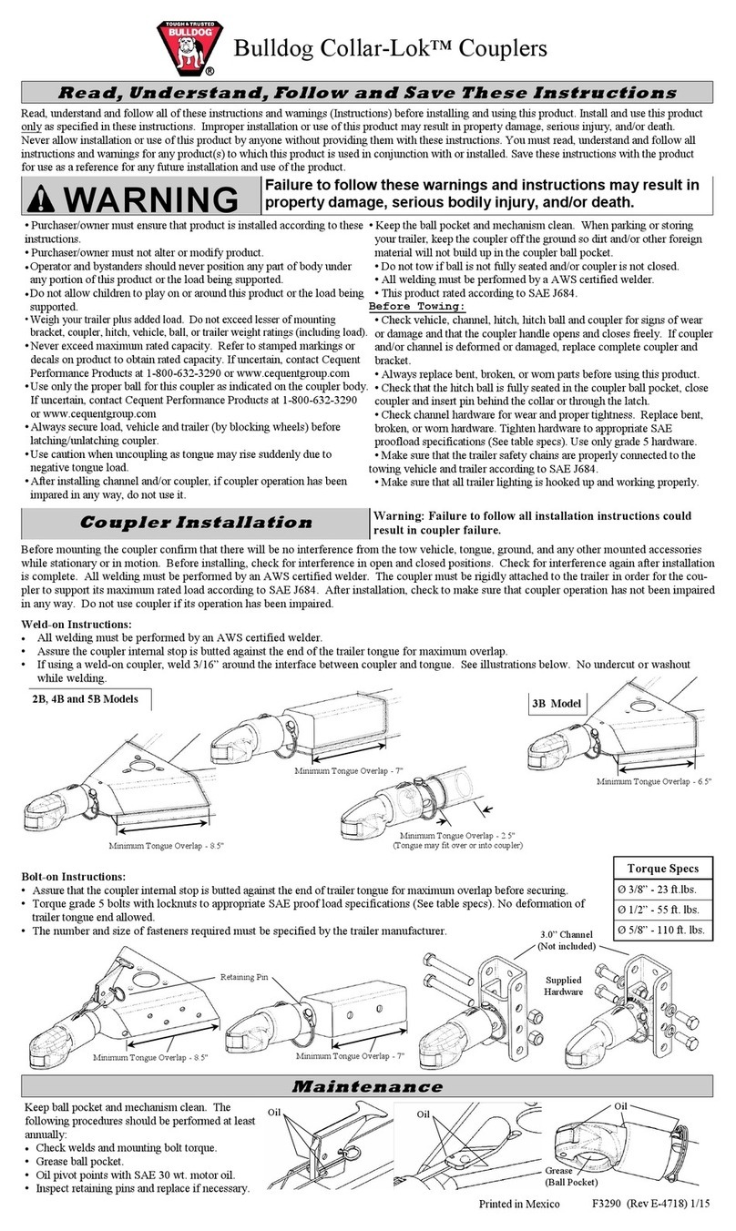
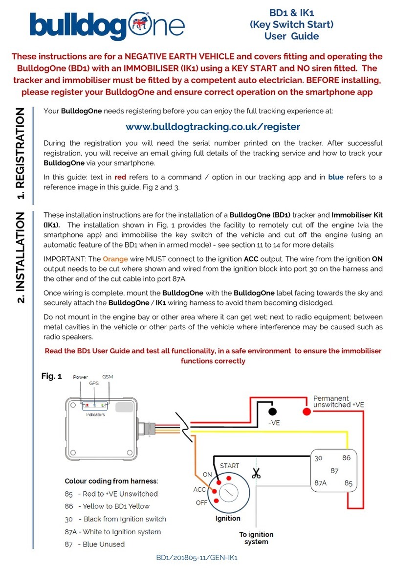
To Operate The Quick Release: To release pressure on the friction discs fit the tubular handle (7) on to cam spigot (4) and lift cam to vertical position.
To apply pressure to the friction discs, simply press down until handle is horizontal, remove handle.
Fitting To The Towing Vehicle
1) Remove the towing ball.
2) Fit the twin car plate (1) between the towing ball and the car towing bracket
(longer high tensile bolts may be necessary).
3) Lift the quick release cam (4) and insert damper pivot bracket (3)
in to the slot in the twin car plate (1) and secure with locking
stud (2). To clear the ‘A’ frame pull the stabiliser towards you.
Repeat for opposite side.
Fitting To a Caravan With A Fairing: When fitting the angle bracket (6) to an ‘A’ frame covered by a plastic
fairing it is advisable to remove the fairing and fit directly to the metal frame using saddle clamp brackets
available from your dealer. Then replace the fairing over the angle bracket.
Fitting To a Trailer.
1) Load the vehicle and trailer as normal and hitch up in line on a level surface.
Please ensure the hitch is fully forward. Then carry out the following to both sides.
2) Push the stabiliser spring arm until it is parallel to the trailer ‘A’ frame.
3) Slide the angle bracket and slipper assembly (6) on to the spring arm leaving 5” (120mm) of
spring protruding.
4) Holding the angle bracket vertical scribe a mark down its edge on to the ‘A’ frame.
Remove the bracket and pull aside the spring arm.
5) In the approximate position of the angle bracket on the trailer ‘A’ frame draw a horizontal centre
line equal distance from the top and bottom flanges.
6) Position the angle bracket vertical to the lines marked on the ‘A’ frame andmark through
any two horizontal holes on to the centre line. Remove bracket.
7) Drill two 8.5mm holes.
8) Slide angle bracket assembly back on to spring arm and push to ‘A’ frame.
9) Lock up quick release and lift spring arm at end between 1½” to 2½”. Insert the two bolts through the
appropriate holes and bolt up with nuts and washers.
VERTICAL LINE
‘A’ FRAME
5”
1½”
TO
2½”
1
2
2
3
4
43
5
5
6
6
7
7
400Q Stabiliser Fitting Instructions
