Bulldog Security DC Series User manual

2
Read, Understand, Follow and Save These Instructions
• Read,understandandfollowalloftheseinstructionsandwarningsbeforeinstallingandusingthis
product.
• Installandusethisproductonlyasspeciedintheseinstructions.
• Improperinstallationoruseofthisproductmayresultinpropertydamage,seriousinjury,and/or
death.
• Neverallowinstallationoruseofthisproductbyanyonewithoutprovidingthemwiththeseinstruc-
tions.
• Youmustread,understandandfollowallinstructionsandwarningsforanyproduct(s)towhichthis
productisusedinconjunctionwithorinstalled.
• Savetheseinstructionswiththeproductforuseasareferenceforanyfutureinstallationanduseof
theproduct.
Table Of Contents
Safety Page
ImportantSafetyMessages......................................................3
KnowYourWinch..............................................................4
5
.............................7
13
... 16
FeaturesandRatings...........................................................
Instructions
InstallationInstructions .............................
OperationInstructions ..........................................................
Maintenance ................................ ...............................
Thesafetyalertsymbolalertsyoutopotentialphysicalinjuryhazards.
Obeyallsafetymessagesthatfollowthissymboltoavoidpossibleinjuryordeath.
WARNINGindicatesahazardous
situationthat,ifnotavoided,
couldresultindeathorserious
injury.
NOTICEindicatesahazardous
situationthat,ifnotavoided,
couldresultinpropertydamage
CAUTIONindicatesahazardous
situationthat,ifnotavoided
couldresultinminoror
moderateinjury.
Throughout this manual WARNING, CAUTION, NOTICE and the SAFETY ALERT SYMBOL will be used.
WARNING CAUTION NOTICE

3
Before First Operation
• Purchaser/ownermustensurethat
productisinstalledaccordingto
theseinstructions.Purchaser/own-
ermustnotalterormodifyproduct.
• Understandyourwinchand
itsinstructions.
• Neverexceedmaximumrated
capacity.Refertostamped
markingsordecalsonproductto
obtainratedcapacity.
• Thewinchisratedatthefirstlayer
ofwireropeonthedrumforinter-
mittent-periodicduty.
Are you ready to pull?
• NEVERoperatethiswinchwhen
undertheinuenceofdrugs,alco-
holormedication.
• ALWAYSremovejewelry
andweareyeprotection.
• Useleatherglovesorahand
savercablestrapwhenhandling
thewirerope.
• NEVERletwinchropeslipthrough
yourhands.
• Nevertouchawinchropeorhook
whensomeoneelseisatthe
controls.
• NEVERtouchwinchropeorhook
whileundertensionorunderload.
• ALWAYSstandclearofwinchrope
andloadandkeepothersaway
whilewinching.
• Donotusethe
winchasaliftingdeviceorahoist
forverticallift.
• Operatorandbystandersshould
neverpositionanypartofbody
underanyportionofthisproductor
theloadbeingsupported.
• Donotallowchildrentoplayon
oraroundthisproductortheload
beingsupported.
• Keep
clearofwinch,rope,hook,and
fairleadwhileoperating.
• Thewinchisnottobe
usedtolift,supportorotherwise
transportpersonnel.
• ALWAYSbeawareof
possiblehotsurfacesatwinch
motor,drumorropeduringorafter
winchuse.
• ALWAYSensuretheoperatorand
bystandersareawareofthestabili-
tyofthevehicleand/orload.
Is your winch ready to pull?
• ALWAYSinspectwinchrope,hook,
andslingsbeforeoperatingwinch.
Frayed,kinkedordamagedwinch
ropemustbereplacedimmediate-
ly.Damagedcomponentsmustbe
replacedbeforeoperation.
• Periodicallycheckmountinghard-
wareforpropertorqueandtighten
ifnecessary.
• ALWAYSremoveanyelementor
obstaclethatmayinterferewith
safeoperationofthewinch.
• ALWAYSbecertaintheanchoryou
selectwillwithstandtheloadand
thestraporchainwillnotslip.
• Wireropecanbreakwithoutwarn-
ing.Alwayskeepasafedistance
fromthewinchandropewhile
underaload.
• ALWAYSkeepwiredpendant
controlleadandpowercordclear
ofthedrum,rope,andrigging.
Inspectforcracks,pinches,
frayedwiresorlooseconnections.
Damagedcomponentsmustbe
replacedbeforeoperation.
• NEVERwrapwinchrope
backontoitself.Useachoker
chainorstrap.
• ALWAYSensurehooklatch
isclosedandnotsupportingload.
• NEVERapplyloadtohook
tiporlatch.Applyloadonlytothe
centerofhook.
• NEVERuseahookwhosethroat
openinghasincreased,orwhose
tipisbentortwisted.
• ALWAYSuseahookwithalatch.
• Neverusewinchropefortowing.
• NEVERuseexcessiveefforttofree
spoolwinchrope.
• ALWAYStaketimetouseappropri-
ateriggingtechniquesforawinch
pull.
During the pull
• NEVERexceedwinchorwinch
roperatedcapacity.Doubleline
usingasnatchblocktoreduce
winchload.
• Donotshockloadthewinch.
• Neveruseawinchtosecureaload.
• ALWAYSunspoolasmuchwinch
ropeaspossiblewhenrigging.
Doublelineorpickdistantanchor
point.
• Neverengageordisengagethe
clutchwhenthewinchisunder
loadorthedrumismoving.
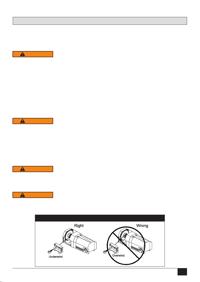
• Pullfromanangleoflessthan5
degreeslaterallyand15degrees
horizontly.Withoutmaintainingthe
propereetangleof+/-5degrees;
(SeeFigure18page15)therope
willpileontoonesideoftherope
drumandpossiblydodamageto
theropeorwinch.Re-spoolyour
winchasrequired.
• Whenwinchingaheavyload,lay
arecoverydamperoraheavy
blanketoverthemiddlethirdofthe
wirerope.
• ALWAYSavoidsidepullswhich
canpileupwinchropeatoneend
ofthedrum.Thiscandamage
winchropeorwinch.
• ALWAYSensuretheclutchis
fullyengagedordisengaged.
Thetypeofdutyisintermittent-
periodicdutyS3andtheloadtime
neverexceeds2minutes.
• NEVERsubmergewinchinwater.
After Use
• Disconnectthehandheldpendant
fromthewinchwhennotinuse.
• ALWAYSstorethependantcontrol
inaprotected,clean,dryarea.
Important Safety Messages

4
Figure 1 - Winch Components
Know Your Winch
Winch
Drum
Pendant Remote
Control Socket
Pendant Remote Control
Roller
Fairlead
Hand Saver
Cable Strap Winch Mounting
Hardware
Clutch
Lever
Circuit Breaker
(Varies Per Model)

5
Features and Ratings
Load Rating
Loadandspeedvariesaccordingtohowmuchwireropeisonthedrum.Therstlayerofropeonthe
drumdeliverstheslowestspeedandthemaximumload.Afulldrumdeliversthemaximumspeedand
theminimumload.Forthisreason,allutilitydutywinchesareratedattheirrstlayercapacities.
Table 1 - Winch Capacity
DC2500 DC3500 DC4500
Rope
Layer
Capacity Length of
Rope on
Drum
Rope
Layer
Capacity Length of
Rope on
Drum
Rope
Layer
Capacity Length of
Rope on
Drum
1st 2,500lbs./
1,134kgs.
10.2ft./
3.1m.
1st 3,500lbs./
1,588kgs.
8.9ft./
2.7m.
1st
4,500lbs./
2,041kgs.
7.9ft./
2.4m.
2nd 2,149lbs./
975kgs.
22ft./
6.7m.
2nd 2,954lbs./
1,340kgs.
19.6ft./
6m.
2nd 3,722lbs./
1,688kgs.
17.4ft./
5.3m.
3rd 1,885lbs./
855kgs.
35.5ft./
10.8m.
3rd 2,555lbs./
1,159kgs.
31.8ft./
9.7m.
3rd 3,174lbs./
1,440kgs.
28.6ft./
8.7m.
4th 1,678lbs./
761kgs.
50ft./
15.2m.
4th 2,251lbs./
1,021kgs.
45.7ft./
13.9m.
4th 2,766lbs./
1,255kgs.
41.4ft./
12.6m.
5th N/A N/A 5th 2,012lbs./
913kgs.
50ft./
15.2m.
5th 2,451lbs./
1,112kgs.
50ft./
15.2m.
Table 2 - Winch Specifications
Powered
Winches DC2500 DC3500 DC4500
Wire rope 3/16”x50’
A7x19
Aircraft
Cable
7/32”x50’
A7x19
Aircraft
Cable
1/4”x50’
A7x19
Aircraft
Cable
Brake Mechanicalanddynamicbrakesholdfullload
Clutch (free-
spooling) Free-spoollever
Control Handheldpendantswitch

6
Features and Ratings
Table 3 - Line Speed And Amp Draw
DC2500 DC3500 DC4500
1st Layer
Line Pull
(lbs./kgs.)
Line Speed
(FPM/
MPM)
Amp
Draw
1st Layer
Line Pull
(lbs./kgs.)
Line Speed
(FPM/
MPM)
Amp
Draw
1st Layer
Line Pull
(lbs./kgs.)
Line Speed
(FPM/
MPM)
Amp
Draw
NoLoad 16.4/5 30 NoLoad 21.3/6.5 25 NoLoad 21.3/6.5 25
1,000/
454
11/3.5 80 1,000/
454
16.4/5 110 1,000/
454
16.4/5 110
2,000/
907
7.5/2.3 150 2,000/
907
11.8/3.6 200 2,000/
907
11.8/3.6 210
2,500/
1,134
4.2/1.3 200 2,500/
1,134
10.5/3.2 230 2,500/
1,134
10.5/3.2 240
N/A N/A N/A 3,000/
1,361
8.2/2.5 260 3,000/
1,361
8.2/2.5 270
N/A N/A N/A 3,500/
1,588
5.9/1.8 300 3,500/
1,588
5.9/1.8 290
N/A N/A N/A N/A N/A N/A 4,000/
1,814
4.6/1.4 310
N/A N/A N/A N/A N/A N/A 4,500/
2,041
1.3/0.4 330
FPM = Feet Per Minute MPM = Meters Per Minute

7
Mounting Hardware Requirements
ALWAYS torque mounting bolts to the values specified for your winch in Table 4 page 8 to prevent
vibration during operation.
ALWAYS use Grade 5 / 8.8 Metric or better hardware.
NEVER weld mounting bolts.
ALWAYS choose the proper bolt length for your application.
ALWAYS confirm required bolt length to ensure proper thread engagement.
BEFORE INSTALLING AND USING YOUR POWERED WINCH, READ AND
FOLLOW ALL MOUNTING INSTRUCTIONS AND SAFETY MESSAGES.
1. Mounting
To prevent accidental activation of the winch and serious injury, complete the winch installation
and attach the hook before installing the wiring.
1. Before Installation
WARNING
Installation Instructions
1.1 Inspect Parts
Hand Saver Cable Strap
Clutch Lever
Instruction/Owners Manual
Winch Assembly
Drum Cover
Pendant Remote Control
Pendant Remote Control Socket
Roller Fairlead
6 Gauge Battery Lead
Hardware
1.2.1 Winch Mounting
1.2 Select Mount Location
ALWAYS choose a mounting location that is sufficiently strong to withstand the maximum pull-
ing capacity of your winch.
WARNING
1. Yourmountingsurfacemustbeequaltoorgreaterthanthefootprintofthewinchframe.
2. Thewireropeshallbeunderwoundasseenbelow.
WARNING
WARNING
Figure 2

8
Installation Instructions
1.3 Determine Mount Position
Failure to adequately align, support, or attach the winch to a suitable mounting base could
result in a loss of efficiency of performance or damage to the winch, wire rope and mounting
surface.
WARNING
1. Makesurethewinchisalignedcorrectly
2. Setwinchinmountinglocation.Conrmrequiredboltlength.
3. Installbolts,nuts,andlockwashersandtightentotorquespeciedinTable4below.
1.4 Install the Winch
Table 4 - Mounting Torque Requirements
Powered
Winches DC2500 DC3500 DC4500
Winch
Mounting
Bolt Size
M10x
1.5pitch
8.8grade
2 Required
M10x
1.5pitch
8.8grade
2 Required
M10x
1.5pitch
8.8grade
2 Required
Winch
Mounting
Bolt Torque
40ft./lbs. 40ft./lbs. 40ft./lbs.
7.48"/190mm
5.59"/142mm
3.66"/93mm
2–ø.433"/
2–ø11mm
FOOTPRINT
Figure 4Figure 3

9
Installation Instructions
WARNING
1.5 Install the Wiring
BEFORE installing the winch, make sure all electrical parts are corrosion free.
ALWAYS place the supplied terminal boots on wires and terminals as directed by the installation
instructions.
NEVER lean over battery while making connections.
NEVER route electrical cables over battery terminals.
ALWAYS consult Electrical Connections section for proper wiring details.
Run the charging system during winching operations to keep battery charged.
NEVER route electrical cables across sharp edges.
NEVER route electrical cables near parts that get hot.
NEVER route electrical cables through or near moving parts.
AVOID pinch and wear/abrasion points when installing all electrical cables.
ALWAYS insulate and protect all exposed wiring and electrical terminals.
Afullychargedbatteryandgoodconnectionsareessentialfortheproperoperationofyourwinch.The
minimumrequirementforthebatteryis650coldcrankingamps.
1.5.1 Battery Recommendations & Lead Size
Table 5 - Wire Gauge Specifications
Model DC2500 DC3500 DC4500
Control Type Solenoid/Indirect
Volt 12V 6AWG×5’(1.5m) 6AWG×5’(1.5m) 6AWG×5’(1.5m)
1. Plantheroutingpath.
2. Looselysecurepowercablesalongpath.
3. Conrmpowercablesareprotectedfromsharpedges,heatandmovingparts.Considerchassis
exandvibrationwhichmightdamagecable.
4. Carefullyinspectelectricalcablerouting.Ziptieandsecureelectricalcables.Ziptiesshouldbe
snug,butnotcuttingintowireinsulation.Useelectricaltape,piecesofrubberhoseorelectrical
conduittoprotectelectricalcablesandwireharnesswhereneededtoavoidelectricalcableinsula-
tionwearorabrasion.
5. FIRSTattachred(positive)batterycable,thenblack(negative)batterycable.Installbootsasappro-
priatetoprotectconnections.Torquebatteryterminalfastenersto124in/lbs(14N-m).SeeFigure5,
page10.
ALWAYS route battery cables along a path that allows the cables to be secured with zip ties.
Loose or unsecured power cables can cause serious injury or death.
Routebatteryconnectioncablesinareasthatwillnotcausethemtowearorcutthroughtheinsulation
causingapotentialshortcircuit.Thewinchpowerwiremustberoutedtothebattery.Adirectbattery
connectionofthepower(red)andground(black)cablesisrequired.
1.5.2 Battery Cable Routing
WARNING

10
Figure 5 - Torque Specification
14 N-m
124 in-lbs.
Installation Instructions
Figure 6 - DC2500, DC3500 & DC4500 Wiring Diagram
Uponcompletionofinstallation,checkwinchforproperoperation.Thevoltagedropforthewinch
motormustnotexceed10%ofthenominalvoltageof12/24DC.
1.5.3 System Check

11
1.6 Know Your Wireless Remote
Installation Instructions
Never lose sight of the winch or jack while using the wireless remote.
Never touch the winch or jack while the remote is in someone else’s hands.
WARNING
1. Transmissionrange:15~27m(50~90ft)
2. Receiveroperationvoltage:8~24V
3. Receiverfusecurrentrating:7.5A
4. Protection:IP-66
5. Operatingtemperaturerange:-20°C~+70°C
6. LEDindication:Greenlightforpoweron;Redlight
foroperating;Blinkinggreenforlowbatterylife;
Blinkingredlightforpoorsignalreceived
1.6.1 Wireless Remote and Transmitter Specifications
Wireless
Receiver
Switch Cord W/3Pin plugs
Ø8 X 1500 mm
Wireless
Transmitter
Lithium Battery:
3V CR2032
Transmitter
Strap
LED Indication
Figure 7 - Wireless Remote Components
Figure 8 - Wireless Remote
1. Connect The Wiring
ConnecttheSwitchcordW/3or6Pin
plugstothesocketonthecontrolpack.
ConnecttheRedwiretothepositive(+)
terminalofthebattery.
ConnecttheBlackwiretothenegative(-)
terminalofthebattery.
1.6.2 Wireless Remote and Transmitter Installation
2. Mount the Receiver
Thereceivershouldbemountedinaclearand
drylocation.
Mountonaatsurfacewithatleast2fasteners
(notincluded)throughthe7mmmountingholes
oneachsideofthereceiver.Minimumofone
mountingfastenereachside
Figure 10 - Mounting
Figure 9 - Connections
Black
RedFuse

12
Installation Instructions
1. Install Battery
a.Removethethreescrewsfromthewireless
transmitter.
b.Separatethetopsection,insertthebattery
positive(+)sideupandreplacethetop
section.
c.Replacethethreescrews.
Lithium Battery:
CR2032 (3V)
2. Test
a.PressthePowerButtonfor5secondsuntiltheGreenlightcomeson.
b.PresstheIn/DownorOut/Upbutton.TheRedindicatorlightwillcomeon.
LED Indicator
Cable OUT
Power Button
Cable IN
Cable OUT
1.6.3 Wireless Remote and Transmitter Installation
Figure 11 - Battery Replacement
Figure 12 - Operations
3. Stop
a.Thesystemwillautomaticallyshutdownthe
transmitterifnotactivatedfor5minutes.
b.PressandholdthePowerButtonfor5sec-
ondstoshutdownthetransmitter.
LED
Indicator
Programming
Button
4. Reset
a.PressandholdtheProgrammingButtonfor5secondsuntiltheRedindicatorilluminates.
b.PressthePowerButtononthetransmitterfor5secondsuntiltheGreenindicatorlightsup.
c.PresstheInorOutbuttononthetransmitteruntiltheRedindicatorlighton
thereceiverturnsoff.
d.Resetisnowcompleted.Pleasenoteonlyoneremotetransmittercanberesetforeachreceiver.
5. Notes
a.Thewirelessremotecontrolandwiredremotecanbeexchangedforactivatingthewinchorjack.
b.BlinkingGreenLEDlightshowsthetransmitterbatteryislow,thebatteryshouldbereplaced
immediately.
c.Pleasenoteonlyoneremotecanberesetforeachreceiver.
d.BlinkingRedLEDforpoorsignal.
Figure 13 - Resting
Cable IN

13
Operation Instructions
ALWAYS use supplied hand saver cable strap whenever spooling winch rope in or out, during
installation or operation to avoid injury to hands and fingers.
2.1 Spooling in Under Load
WARNING
NEVER exceed winch’s rated line pull. Power-in the winch rope evenly and tightly on the drum.
This prevents the outer winch wraps from sinking into the inner wraps, binding and damaging
the winch rope.
NEVER touch winch rope or hook while someone else is at the control switch or during winch-
ing operation.
WARNING
Donotshockloadthewinchwhenspooling.Avoidshockloadswhenspoolingbypulsingthecontrol
switchtotakeupwinchropeslack.Shockloadscanmomentarilyfarexceedthewinchandroperatings.
DO NOT power the hook into the fairlead. This could cause damage to the fairlead.
NOTICE
2.4 Safe Working Conditions
2.3 Stretching the Wire Rope
ALWAYS pre-stretch rope and re-spool under load before use. Tightly wound rope reduces
chances of “binding”, which can damage the rope.
NEVER operate winch with less than five (5) wraps of wire rope around the drum. Rope could
come loose from the drum, as the rope attachment to the drum is not designed to hold a load.
Thegoalofstretchingyourwireropeistowrapittightlyonthewinchdrumsothatitcansupportad-
ditionallayersofwire.Thiscanbeaccomplisehdwithavehiclesuppliedasdeadweighttostretchthe
rope.Thisisanexercisethatwillmakeyourwireropelastlonger,avoidtanglesandensureatightly
wrappedwinch.Usecaretoevenlywrapeachlayertopreventdamagetotherope.
2.2 Overloading / Overheating
Thetypeofdutyisintermittent-periodicdutyS3andtheloadtimeneverexceeds2minutes.When
themotorapproachesstallspeed,veryrapidheatbuildupoccurswhichmaycausemotordamage.
Double-lineriggingwillreducetheamperagedraw,andreduceheatbuildupinthemotor.Thisallows
longercontinualuse.
WARNING
NEVER work around the winch rope while under load.
NEVER step over a winch rope while under load.
ALWAYS use caution when working with electricity and remember to verify that no exposed
electrical connections exist before energizing your winch circuit.
WARNING
WARNING
TheoperatorshouldALWAYSoperatethewinchfromasafepositionwhenpullingaload.Thesafe
areasare:Perpendiculartothewinchrope.
Thesafepositionwillhelppreventthewireropefromstrikingtheoperatorifthewireropefailswhen
underload.
Fullyextendthependantcontrolcordtooperatewinchwheneverpossible.Theoperatormusttryto
maintainatleast8ft.(2.44m)fromthewinchwhileoperating.

14
2.5.1 Handheld Pendant Control
Industrialgradeandwaterproofremote.DC2500,
DC3500andDC4500winchesincludesLED
overheatingindicator.
2.5.2 Connect the remote control
Alwayskeeptheremotecontrolwireclearofthe
winch,wireropeandrollerfairlead.Figure14.
DO NOT leave the pendant control plugged
into the winch when not in use. This may result
in a dangerous condition and/or battery drain.
1. PressandholdtheCableInButtonforrope
windinginoperation.
2. PressandholdtheCableOutButtonforrope
windingoutoperation.
3. Tostopwinching,releasetheCableInorCable
OutButtons.Figure15.
Cable-Out
Figure 15 - Cable Button
Figure 14 - Connect Remote
2.5 For First Time operation
2.6 Clutch Operation
NEVER engage or disengage clutch if winch is under load, winch rope is in tension or drum is
moving.
To prevent damage, ALWAYS fully engage or fully disengage the clutch lever.
WARNING
Theclutchleverallowsrapidwireropepayout
forhookingontotheloadoranchorpointsandis
operatedbyaclutchlever.
Theclutchlevermustbeinthe
“Engaged”positionbeforewinching(g16)
1. Todisengagetheclutchlifttheclutchleverto
the“Disengaged”position,wireropecannow
befreespooledonthedrum(g17)
2. Toengagetheclutch,lowertheclutchleverto
the"Engaged"position
3. Iftheclutchlevercan’tbeproperlylockedin
the“Disengaged”position,rotatethedrumto
intoapositionbyhandtoEngageorDisengage
completely.
4. Wearleatherglovesanduseahandsaverstrap
whenguidingthewireropeoutofthedrum.
Cable-In
Operation Instructions
Figure 16 - Engaged Clutch
Engaged
Figure 17 - Disengage Clutch
To disengage,
lift the clutch lever
Clutch
Lever
WARNING

15
2.7.1 Calculating Fleet Angle
Toobtainthebestwireropeservice,thedirectionofpullwillbe
onahorizontalwithin±15degreesandperpendiculartothecen-
terlineofthewinchdrumwithin±5degrees.Shortpullsofupto
45degreeslaterallyareacceptable;howeverwithoutmaintaining
thepropereetangle;theropewillpileontoonesideoftherope
drumandpossiblydodamagetotheropeorwinch.Re-spool
yourwinchasrequired.Figure18
2.7 Winching Principles
2.7.2 Recovery Damper
Arecoverydamperisasafetydevicedesignedtohelpreduce
thepossibilityofinjuryorpropertydamageintheeventofa
wireropefailure.Placeinthemiddlethirdofaliverope.
Figure19.
2.7.3 Snatch Block
Animportantaidtosuccessfulwinchingisthe
useofsnatchblock,whichcanbeusedto
increasethepullingpowerofawinchorchange
thedirectionofapull.
Awinchdoublelinedwithasnatchblockcreates
amechanicalleveragecuttingtheeffortrequired
bynearlyhalf.
Theuseofonesnatchblockshowsanindirect
pullwherethevehicleislimitedduetounsuitable
groundorobstruction.Thepullontheloadis
theactuallinepullofthewinch.Ifmorethanone
snatchblockisused,theymustbelocatedat
least40"(100cm)apart.Figure20.
Figure 18 - Fleet Angle
Roller
Fairlead
Figure 19 - Recovery Damper
Figure 20 - Snatch Block
Snatch
Block
Operation Instructions
CAUTION
WARNING

16
ThePower-Outfunctiondrivesthewinchmotoragainstthebrakewhichissimilartodrivingyour
vehiclewiththeparkingbrakeengaged.DonotusethePower-Outfunctionforloweringaload--
winchesarenotdesignedtobeusedashoists.Usethefree-spoolfunctiontopayoutwirerope.
IfyouPower-Outover25feet,letthewinchcoolfor15minutes.
Do not use the winch as a lifting device or a hoist for vertical lifting.
WARNING
The Power-Out function should be used for relieving tension on the rope,
not for extended distances.
CAUTION
Operation Instructions
Maintenance
Neversubstituteaheavierorlighterrope.Neveruseropemadeofanymaterialotherthanwire.
1.Un-spooltheentirewirerope,thentakeitoutfromthedrum.
2.Putthereplacementwireropethroughthefairleadopening,passbelowthedrum,andinsertitinto
theholeofdrumcore.
3.Tightenthescrewdownwardstosecurethewirerope.
Figure 21
ALWAYS complete the winch installation and hook attachment before installing the wiring.
ALWAYS pre-stretch rope and re-spool under load before use. Tightly wound rope reduces
chances of “binding”, which can damage the rope.
A minimum of five (5) wraps of steel wire rope around the drum is necessary to support the
rated load.
ALWAYS spool the winch rope onto the drum in the direction specified by the drum rotation
labels on the winch and/or in the documentation. This is required for the automatic brake to
function properly.
3.1 Install/Replace the Rope
WARNING

17
3.2 Lubrication
Allmovingpartsinthewincharepermanentlylubricatedatthetimeofassembly.Undernormalcondi-
tionsfactorylubricationwillsufce.Ifre-lubricationofgearboxisnecessaryafterrepairordisassem-
blyuseShellEP2orequivalentgrease.RegularlylubricateClutchLeverwithlightoil.Neverlubricate
thebrakesystem.
Maintenance
•Check the wire rope. Beforewinching,make
suretheropeiswoundonthedrumevenly.If
thereismixedwinding,itisessentialtorewindit
evenly.
• Becarefultokeeptheropeundertension.Never
guideawireropeontothedrumwithyourhand,
useahandsavercablestrap.
Figure 22 - Mixed Winding

18
Troubleshooting
Table 6 - Troubleshooting
Symptom Possible Cause Remedy
Winch will
not operate
Cut circuit Check battery lead
Weak battery Recharge or replace battery, 650CCA
Damaged circuit breaker Replace circuit breaker
Bad connection of wiring Reconnect tightly
Damaged DC solenoid Replace DC solenoid
Cut circuit on switch Replace switch
Damaged motor or carbon brush Replace motor or carbon brush
Poor or lost connections to motor Replace wiring or tighten it
Motor runs in
one direction.
Broken wiring or bad connections Reconnect or replace wiring
Damaged or stuck DC solenoid Replace DC solenoid
Switch inoperative Replace switch
Drum will
not clutch.
Clutch does not disengage Replace clutch
Damaged 1st shaft Replace 1st shaft
Damaged brake cam and disc Replace brake cam and disc
Damaged output shaft Replace output shaft
No brake
The gear train is mechanically binding up Check to insure the winch is mounted
on a flat, rigid surface
Damaged brake cam and disc Replace brake cam and disc
Damaged gear box Replace gear box
Broken retaining ring Replace retaining ring
Oil leakage into brake cavity Repair and clean oil leakage
Damaged or inoperative spiral spring Replace and position spiral spring
Brake distance
is too long
Worn brake disc or loose brake spacer Replace brake disc
Oil leakage into brake cavity Repair and clean oil leakage
Brake will
be locked
Too much brake disc powder in the brake hub
Clean brake hub
Over tensioned spiral spring Adjust tension on spiral spring
Stuck between brake disc and gear box Replace with new brake assembly
Damaged
gear box
Hit by certain exterior force Replace the damaged components
Damaged gear train Replace the damaged components
Over load operation
Stop the winch operation and reduce the load
Motor runs
extremely hot
Long period of operation Allow to cool
Damaged motor Replace or repair motor
Damaged or inoperative brake Replace or repair brake

19
Checklist
Table 7 - Checklist
Classification of Check
Item Checking
method Checking
reference
Daily
Periodical
Monthly
Yearly
x
Installation Mounting bolts &
alignment Bolt tension &
wear Existence of
abnormalities
x
Remote control
Working Manual Reasonable
actuation
x
Wearing in
contact points Visual Free of wear
or damage
x
Wire rope
Broken strands Visual,
measuring Less than 10%
x x
Rope Visual,
measuring 7% of nominal
diameter max
x
Fastening
condition of end Visual Existence of
abnormalities
x
Deforming or
corrosion Visual Existence of
abnormalities
x
Clutch
assembly Damaged clutch
assembly
Visual
evidence
of wear
Free of wear
or damage
x
Motor Staining, damage Visual
evidence
of wear
Existence of
abnormalities
x
Brake
Wearing of
brake disc
Visual
evidence
of wear
Free of wear or
damage
x
Performance Visual Reasonable
actuation
x
Gear Damage, wear Visual
evidence
of wear
Free of wear
or damage

Checklist
Table 8 - Checklist
Before
First
Operation
After
EVERY
Use
Every
90 Days
Read, understand and follow the warnings
and instructions in this manual. X
Check all fasteners and verify they are at the
proper torque.
Replace fasteners as needed. X X
Check that the wiring is correct and the
connections are tight X X
Check that there are no bare or exposed
wires, terminals, or damage to the cables.
Cover terminals with boots. Repair or
replace wires as needed. X X
If damaged, discontinue use and replace
rope immediately. XXX
Keep winch, rope, and switch control free
from contaminants.
Use a clean rag or towel to remove any dirt
and debris. X
Looking for trailer hitches and towing? Visit our website.
Other manuals for DC Series
2
This manual suits for next models
3
Table of contents
Other Bulldog Security Winch manuals
Popular Winch manuals by other brands

Falltech
Falltech DuraTech 85' User instruction manual

Runva
Runva EWB25000 Assembly & operating instructions

KFI
KFI Tiger Tail instruction manual

Selden
Selden S30 manual

Kolpin Outdoors
Kolpin Outdoors 25-2360 Assembly & owners manual

Ingersoll-Rand
Ingersoll-Rand FORCE5i FA2i-MRA Product Maintenance Information