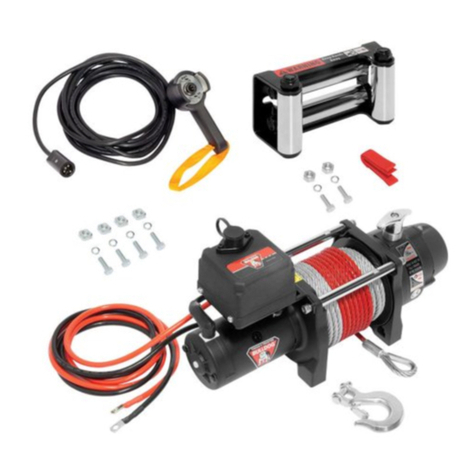
Bulldog Security DC Series User manual

DC Series Utility Winches
Owners Manual
DC Series Treuils électriques
Manuel d’instructions
Serie DC Cabrestantes eléctrico
Manual de instrucciones
DC2.5, DC3.5, DC4.5

HORIZON GLOBAL • F4106-00 REV A (9528) 11/17
2
Read, Understand, Follow and Save These Instructions
• Read, understand and follow all of these instructions and warnings before installing and using this
product.
• Install and use this product only as specied in these instructions.
• Improper installation or use of this product may result in property damage, serious injury, and/or
death.
• Never allow installation or use of this product by anyone without providing them with these instruc-
tions.
• You must read, understand and follow all instructions and warnings for any product(s) to which this
product is used in conjunction with or installed.
• Save these instructions with the product for use as a reference for any future installation and use of
the product.
Table Of Contents
Safety Page
Important Safety Messages ...................................................... 3
Know Your Winch .............................................................. 4
Features and Ratings ........................................................... 5
Instructions
Installation Instructions .......................................................... 6
Operation Instructions .......................................................... 10
Maintenance .................................................................. 13
How To Order ................................................................. 14
Checklist ..................................................................... 15
Legal ........................................................................ 16
Limited Warranty............................................................... 17
The safety alert symbol alerts you to potential physical injury hazards.
Obey all safety messages that follow this symbol to avoid possible injury or death.
WARNING indicates a hazardous
situation that, if not avoided,
could result in death or serious
injury.
NOTICE indicates a hazardous
situation that, if not avoided,
could result in property damage
CAUTION indicates a hazardous
situation that, if not avoided
could result in minor or
moderate injury.
Throughout this manual WARNING, CAUTION, NOTICE and the SAFETY ALERT SYMBOL will be used.
WARNING CAUTION NOTICE

HORIZON GLOBAL • F4106-00 REV A (9528) 11/17 3
Before First Operation
• Purchaser/owner must ensure that
product is installed according to
these instructions. Purchaser/own-
er must not alter or modify product.
• Understand your winch and
its instructions.
• Never exceed maximum rated ca-
pacity. Refer to stamped markings
or decals on product to obtain rat-
ed capacity. If uncertain, contact
Horizon Global at 1-800-632-3209
or bulldogproducts.net
• The winch is rated at the rst layer
of wire rope on the drum for inter-
mittent-periodic duty.
Are you ready to pull?
• NEVER operate this winch when
under the inuence of drugs, alco-
hol or medication.
• ALWAYS remove jewelry
and wear eye protection.
• Use leather gloves or a hand
saver cable strap when handling
the wire rope.
• NEVER let winch rope slip through
your hands.
• Never touch a winch rope or hook
when someone else is at the
controls.
• NEVER touch winch rope or hook
while under tension or under load.
• ALWAYS stand clear of winch rope
and load and keep others away
while winching.
• Do not use the
winch as a lifting device or a hoist
for vertical lift.
• Operator and bystanders should
never position any part of body
under any portion of this product or
the load being supported.
• Do not allow children to play on
or around this product or the load
being supported.
• Keep
clear of winch, rope, hook, and
fairlead while operating.
• The winch is not to be
used to lift, support or otherwise
transport personnel.
• ALWAYS be aware of
possible hot surfaces at winch
motor, drum or rope during or after
winch use.
• ALWAYS ensure the operator and
bystanders are aware of the stabili-
ty of the vehicle and/or load.
Is your winch ready to pull?
• ALWAYS inspect winch rope, hook,
and slings before operating winch.
Frayed, kinked or damaged winch
rope must be replaced immediate-
ly. Damaged components must be
replaced before operation.
• Periodically check mounting hard-
ware for proper torque and tighten
if necessary.
• ALWAYS remove any element or
obstacle that may interfere with
safe operation of the winch.
• ALWAYS be certain the anchor you
select will withstand the load and
the strap or chain will not slip.
• Wire rope can break without warn-
ing. Always keep a safe distance
from the winch and rope while
under a load.
• ALWAYS keep wired pendant
control lead and power cord clear
of the drum, rope, and rigging.
Inspect for cracks, pinches,
frayed wires or loose connections.
Damaged components must be
replaced before operation.
• NEVER wrap winch rope
back onto itself. Use a choker
chain or strap.
• ALWAYS ensure hook latch
is closed and not supporting load.
• NEVER apply load to hook
tip or latch. Apply load only to the
center of hook.
• NEVER use a hook whose throat
opening has increased, or whose
tip is bent or twisted.
• ALWAYS use a hook with a latch.
• Never use winch rope for towing.
• NEVER use excessive effort to free
the spool winch rope.
• ALWAYS take time to use appropri-
ate rigging techniques for a winch
pull.
During the pull
• NEVER exceed winch or winch
rope rated capacity. Double line
using a snatch block to reduce
winch load.
• Do not shock load the winch.
• Never use a winch to secure a load.
• ALWAYS unspool as much winch
rope as possible when rigging.
Double line or pick distant anchor
point.
• Never engage or disengage the
clutch when the winch is under
load or the drum is moving.
• Pull from an angle of less than 5
degrees laterally and 15 degrees
horizontally. Without maintaining
the proper eet angle of +/- 5 de-
grees; (See Figure 10 page 12) the
rope will pile onto one side of the
rope drum and possibly do damage
to the rope or winch. Re-spool your
winch as required.
• When winching a heavy load, lay
a recovery damper or a heavy
blanket over the middle third of the
wire rope.
• ALWAYS avoid side pulls which
can pile up winch rope at one end
of the drum. This can damage
winch rope or winch.
• ALWAYS ensure the clutch is
fully engaged or disengaged.
The type of duty is intermittent-
periodic duty S3 and the load time
never exceeds 2 minutes.
• NEVER submerge winch in water.
After Use
• Disconnect the hand held pendant
from the winch when not in use.
• ALWAYS store the pendant control
in a protected, clean, dry area.
Important Safety Messages

HORIZON GLOBAL • F4106-00 REV A (9528) 11/17
4
Figure 1 - Winch Components
Know Your Winch
Pendant Remote Control
Control Box / Cable Assembly
Handlebar Remote Control
Snatch Block
Winch
Hand Saver
Cable Strap Hook

HORIZON GLOBAL • F4106-00 REV A (9528) 11/17 5
Features and Ratings
Load Rating
Load and speed varies according to how much wire rope is on the drum. The rst layer of rope on the
drum delivers the slowest speed and the maximum load. A full drum delivers the maximum speed and
the minimum load. For this reason, all utility duty winches are rated at their rst layer capacities.
Table 1 - Winch Capacity
DC2.5 DC3.5 DC4.5
Rope
Layer
Capacity Length of
Rope on
Drum
Rope
Layer
Capacity Length of
Rope on
Drum
Rope
Layer
Capacity Length of
Rope on
Drum
1st 2,500 lbs./
1,134 kgs.
6.9 ft./
2.1m
1st 3,500 lbs./
1,588 kgs.
5.9 ft./
1.8 m.
1st
4,500 lbs./
2,041 kgs.
12.2 ft./
3.7 m.
2nd 2,033 lbs./
922 kgs.
15.1 ft./
4.6 m.
2nd 2789 lbs./
1,265 kgs.
13.5 ft./
4.1 m.
2nd 3,841 lbs./
1,742 kgs.
26.2 ft./
8 m.
3rd 1,713 lbs./
777 kgs.
24.3 ft./
7.4 m.
3rd 2,319 lbs./
1,052 kgs.
22 ft./
6.7 m.
3rd 3,310 lbs./
1501 kgs.
41.9 ft./
12.8 m.
4th 1,480 lbs./
671 kgs.
34.1 ft./
10.4 m.
4th 1,984 lbs./
900 kgs.
31.2 ft./
9.5 m.
4th 2,907 lbs./
1,319 kgs.
47.6 ft./
14.5 m.
5th 1,303 lbs./
591 kgs.
45.9 ft./
14 m.
5th 1,733 lbs./
786 kgs.
42 ft./
12.8 m.
5th N/A N/A
Table 2 - Winch Specifications
Powered Winches DC2.5 DC3.5 DC4.5
Wire or synthetic
rope
3/16” x 46’
A7 x 19
Aircraft
Cable
7/32” x 42’
A7 x 19
Aircraft
Cable
15/64" x 47.6'
A7 x 19
Aircraft
Cable
Brake Mechanical brakes hold full load
Clutch (free-spooling) Free-spool knob
Control Hand held pendant switch and handlebar mounted control switch
Table 3 - Line Speed And Amp Draw
DC2.5 DC3.5 DC4.5
1st Layer
Line Pull
(lbs./kgs.)
Line Speed
(FPM/
MPM)
Amp
Draw
1st Layer
Line Pull
(lbs./kgs.)
Line Speed
(FPM/
MPM)
Amp
Draw
1st Layer
Line Pull
(lbs./kgs.)
Line Speed
(FPM/
MPM)
Amp
Draw
No Load 14.1 / 4.3 20 No Load 10.5 / 3.2 20 No Load 12.8 / 3.9 28
500/
227
9.8 / 3.0 55 1,000/
454
8.9 / 2.7 75 1,000/
454
9.8 / 3.0 80
1,500/
680
7.5 / 2.3 95 2,000/
907
7.5 / 2.3 130 2,000/
907
8.5 / 2.6 120
2,500/
1,134
4.3 / 1.3 160 3,500/
1,588
4.6 / 1.4 200 3,000/
1,361
6.9 / 2.1 160
4,500/
2,041
4.6 / 1.4 220
FPM = Feet Per Minute MPM = Meters Per Minute

HORIZON GLOBAL • F4106-00 REV A (9528) 11/17
6
Mounting Hardware Requirements
ALWAYS torque mounting bolts to the values specified for your winch in Table 4 page 8 to prevent
vibration during operation.
ALWAYS use Grade 5 / 8.8 Metric hardware.
NEVER weld mounting bolts.
ALWAYS choose the proper bolt length for your application.
ALWAYS confirm required bolt length to ensure proper thread engagement.
BEFORE INSTALLING AND USING YOUR POWERED WINCH, READ AND
FOLLOW ALL MOUNTING INSTRUCTIONS AND SAFETY MESSAGES.
1. Mounting
To prevent accidental activation of the winch and serious injury, complete the winch installation
and attach the hook before installing the wiring.
1. Before Installation
WARNING
Installation Instructions
1.1 Inspect Parts
Hand Saver Cable Strap
Clutch Knob
Instruction/Owners Manual
Winch Assembly
Pendant Remote Control
Pendant Remote Control Socket
Roller Fairlead
Control Box
Handle Bar Control Switch
Snatch Block
Hook
Hardware
1.2.1 Winch Mounting
1.2 Select Mount Location
ALWAYS choose a mounting location that is sufficiently strong to withstand the maximum
pulling capacity of your winch.
WARNING
1. Your mounting surface must be equal to or greater than the footprint of the winch frame.
2. The wire rope shall be underwound as seen below.
WARNING
WARNING
Figure 2
Wrong
Right
Overwind
Underwind

HORIZON GLOBAL • F4106-00 REV A (9528) 11/17 7
Installation Instructions
1.3 Determine Mount Position
Failure to adequately align, support, or attach the winch to a suitable mounting base could
result in a loss of efficiency of performance or damage to the winch, wire rope and mounting
surface.
WARNING
Your winch is designed with a bolt pattern that is standard in this class of winch. Many winch mounting kits
are available that utilize this bolt pattern for the popular vehicles and mounting channels. If you will utilize
the mounting channel you must ensure that it is mounted on a at surface so that the three major sections
(motor, drum and gear housing) are properly aligned. Proper alignment of the winch will allow even distribu-
tion of the full rated load.
Start by connecting the roller fairlead to the mounting channel using 2 each of the cap screw, at washer
and lock washer and tighten to torque specied in Table Four. (Make sure the screw is placed through the
mounting channel and roller fairlead from inside the channel. This will allow enough clearance for the winch
to be placed in the channel without obstruction.)
Assemble the winch to the mounting channel by rst rotating the clutch knob to “CLUTCH OUT” position.
Pull out a few inches of cable from the drum and feed the wire loop through the opening in the front of the
mounting channel and roller fairlead. Now, using the remaining cap screws secure the winch to the mount-
ing channel and tighten to torque specied in Table Four.
Assemble the clevis hook to the cable. Remove the cotter pin from the clevis hook, connect the clevis hook
to the cable and insert the cotter pin back to the clevis hook, bend the cotter pin to secure it.
Always use the hand saver when free-spooling and re-spooling the wire rope. Using the hand saver keeps
your hands and ngers away from the rotating drum.
1.4 Install the Winch
Figure 3
DC2.5 & DC3.5 DC4.5
Figure 4

HORIZON GLOBAL • F4106-00 REV A (9528) 11/17
8
WARNING
1.5 Install the Wiring
BEFORE installing the winch, make sure all electrical parts are corrosion free.
ALWAYS place the supplied terminal boots on wires and terminals as directed by the installation
instructions.
NEVER lean over battery while making connections.
NEVER route electrical cables over battery terminals.
ALWAYS consult Electrical Connections section for proper wiring details.
Run the charging system during winching operations to keep battery charged.
NEVER route electrical cables across sharp edges.
NEVER route electrical cables near parts that get hot.
NEVER route electrical cables through or near moving parts.
AVOID pinch and wear/abrasion points when installing all electrical cables.
ALWAYS insulate and protect all exposed wiring and electrical terminals.
A fully charged battery and good connections are essential for the proper operation of your winch. The
minimum requirement for the battery is 650 cold cranking amps.
1.5.1 Battery Recommendations & Lead Size
Table 5 - Wire Gauge Specifications
Model DC2.5 DC3.5 DC4.5
Control Type Contactor
Volt 12V 10 AWG x 4' winch to
contactor and 6' from the
motor to the battery leads
10 AWG x 4' winch to
contactor and 6' from the
motor to the battery leads
10 AWG x 4' winch to
contactor and 6' from the
motor to the battery leads
Table 4 - Mounting Torque Requirements
Powered
Winches DC2.5 DC3.5 DC4.5
Winch and
Fairlead
Mounting
Bolt Size
M10 x
1.5 pitch
8.8 grade
6 Required
M10 x
1.5 pitch
8.8 grade
6 Required
M10 x
1.5 pitch
8.8 grade
6 Required
Winch
Mounting
Bolt Torque
40 ft./lbs. 40 ft./lbs. 40 ft./lbs.
Installation Instructions

HORIZON GLOBAL • F4106-00 REV A (9528) 11/17 9
Installation Instructions
1. Plan the routing path.
2. Loosely secure power cables along path.
3. Conrm power cables are protected from sharp edges, heat and moving parts. Consider chassis
ex and vibration which might damage cable.
4. Carefully inspect electrical cable routing. Zip tie and secure electrical cables. Zip ties should be
snug, but not cutting into wire insulation. Use electrical tape, pieces of rubber hose or electrical
conduit to protect electrical cables and wire harness where needed to avoid electrical cable insula-
tion wear or abrasion.
5. FIRST attach red (positive) battery cable, then black (negative) battery cable. Install boots as appropri-
ate to protect connections.
ALWAYS route battery cables along a path that allows the cables to be secured with zip ties.
Loose or unsecured power cables can cause serious injury or death.
Route battery connection cables in areas that will not cause them to wear or cut through the insulation
causing a potential short circuit. The winch power wire must be routed to the battery. A direct battery
connection of the power (red) and ground (black) cables is required.
1.5.2 Battery Cable Routing
WARNING
Upon completion of installation,
check winch for proper
operation. The voltage drop
for the winch motor must not
exceed 10% of the nominal
voltage of 12 VDC.
Check for proper drum rotation.
Turn the clutch knob to the
“CLUTCH OUT” position. Pull
out some cable from the drum,
and then turn the clutch knob
to the “CLUTCH IN” position
to engage the gears. Press the
cable out button on the power
switch. If the drum is turning
and releasing more cable then
your connections are accurate.
If the drum is turning and col-
lecting more cable then reverse
the leads on the motor. Repeat
and check rotation.
1.5.3 System Check Figure 5 - DC2.5, DC3.5, & DC4.5 Wiring Diagram
Switch
Red Motor +
Black Motor -
Red Battery +
Black Battery -

HORIZON GLOBAL • F4106-00 REV A (9528) 11/17
10
Operation Instructions
ALWAYS use supplied hand saver cable strap whenever spooling winch rope in or out, during
installation or operation to avoid injury to hands and fingers.
2.1 Spooling in Under Load
WARNING
NEVER exceed winch’s rated line pull. Power-in the winch rope evenly and tightly on the drum.
This prevents the outer winch wraps from sinking into the inner wraps, binding and damaging
the winch rope.
NEVER touch winch rope or hook while someone else is at the control switch or during winch-
ing operation.
WARNING
Do not shock load the winch when spooling. Avoid shock loads when spooling by pulsing the control
switch to take up winch rope slack. Shock loads can momentarily far exceed the winch and rope ratings.
DO NOT power the hook into the fairlead. This could cause damage to the fairlead.
NOTICE
2.3 Safe Working Conditions
2.2 Overloading / Overheating
The type of duty is intermittent-periodic duty S3 and the load time never exceeds 2 minutes. When
the motor approaches stall speed, very rapid heat buildup occurs which may cause motor damage.
Double-line rigging will reduce the amperage draw, and reduce heat buildup in the motor. This allows
longer continual use.
NEVER work around the winch rope while under load.
NEVER step over a winch rope while under load.
ALWAYS use caution when working with electricity and remember to verify that no exposed
electrical connections exist before energizing your winch circuit.
WARNING
WARNING
The operator should ALWAYS operate the winch from a safe position when pulling a load. The safe
areas are: Perpendicular to the winch rope.
The safe position will help prevent the wire rope from striking the operator if the wire rope fails when
under load.
Fully extend the pendant control cord to operate winch whenever possible. The operator must try to
maintain at least 8 ft. (2.44 m) from the winch while operating.

HORIZON GLOBAL • F4106-00 REV A (9528) 11/17 11
2.4.1 Handheld Pendant Control
Utility Grade Remote with 100" cord.
2.4.2 Connect the remote control
Always keep the remote control wire clear of the
winch, wire rope and roller fairlead.
DO NOT leave the pendant control plugged
into the winch when not in use. This may result
in a dangerous condition and/or battery drain.
1. Press and hold the Cable In Button for rope
winding in operation.
2. Press and hold the Cable Out Button for rope
winding out operation.
3. To stop winching, release the Cable-In or
Cable -Out buttons on the handle bar remote.
Figure 7.
Cable-Out
Figure 7 - Cable Button
Figure 6 - Connect Remote
2.4 For First Time operation
2.5 Clutch Operation
NEVER engage or disengage clutch if winch is under load, winch rope is in tension or drum is
moving.
To prevent damage, ALWAYS fully engage or fully disengage the clutch knob.
WARNING
The clutch knob allows rapid wire rope payout for
hooking onto the load or anchor points.
The clutch knob must be in the
“Engaged” position before winching (Figure 8).
1. To disengage the clutch rotate the clutch knob
to the “Disengaged” position, wire rope can
now be free-spooled from the drum (Figure 9).
2. To engage the clutch, rotate the clutch knob to
the "Engaged" position.
3. If the clutch knob cannot be properly locked in
the “Disengaged” position, rotate the drum to
into a position by hand to Engage or Disengage
completely.
4. Wear leather gloves and use a handsaver strap
when guiding the wire rope in or out of the
drum.
Cable-In
Operation Instructions
Figure 8 - Engaged Clutch
Engaged
Figure 9 - Disengage Clutch
To disengage,
turn the clutch knob
Clutch
Knob
WARNING

HORIZON GLOBAL • F4106-00 REV A (9528) 11/17
12
2.6.1 Calculating Fleet Angle
To obtain the best wire rope service, the direction of pull will be
on a horizontal within ±15 degrees and perpendicular to the cen-
terline of the winch drum within ±5 degrees. Short pulls of up to
45 degrees laterally are acceptable; however without maintaining
the proper eet angle; the rope will pile onto one side of the rope
drum and possibly do damage to the rope or winch. Re-spool
your winch as required. Figure 10.
2.6 Winching Principles
2.6.2 Recovery Damper
A recovery damper is a safety device designed to help reduce
the possibility of injury or property damage in the event of a
wire rope failure. Place in the middle third of a live rope.
Figure 11.
2.6.3 Snatch Block
An important aid to successful winching is the
use of snatch block, which can be used to
increase the pulling power of a winch or change
the direction of a pull.
A winch double lined with a snatch block creates
a mechanical advantage cutting the effort re-
quired by nearly half.
The use of one snatch block shows an indirect
pull where the vehicle is limited due to unsuitable
ground or obstruction. The pull on the load is
the actual line pull of the winch. If more than one
snatch block is used, they must be located at
least 40" (100 cm) apart. Figure 12.
Figure 10 - Fleet Angle
Roller
Fairlead
Figure 11 - Recovery Damper
Figure 12 - Snatch Block
Snatch
Block
Operation Instructions
CAUTION
WARNING

HORIZON GLOBAL • F4106-00 REV A (9528) 11/17 13
The Power-Out function drives the winch motor against the brake which is similar to driving your
vehicle with the parking brake engaged. Do not use the Power-Out function for lowering a load --
winches are not designed to be used as hoists. Use the free-spool function to pay out wire rope.
If you Power-Out over 25 feet, let the winch cool for 15 minutes.
Do not use the winch as a lifting device or a hoist for vertical lifting.
WARNING
The Power-Out function should be used for relieving tension on the rope,
not for extended distances.
CAUTION
Operation Instructions
Maintenance
Never substitute a heavier or lighter rope.
1. Un-spool the entire wire rope, then take it out from the drum.
2. Put the replacement wire rope through the fairlead opening, pass below the drum, and insert it into
the hole of drum core.
3. Tighten the screw downwards to secure the rope. Figure 13
Figure 13
ALWAYS complete the winch installation and hook attachment before installing the wiring.
A minimum of five (5) wraps of steel wire rope, (10) ten wraps for synthetic rope, around the
drum is necessary to support the rated load.
ALWAYS spool the winch rope onto the drum in the direction specified by the drum rotation
labels on the winch and/or in the documentation. This is required for the automatic brake to
function properly.
3.1 Install/Replace the Rope
WARNING

HORIZON GLOBAL • F4106-00 REV A (9528) 11/17
14
3.2 Lubrication
All moving parts in the winch are permanently lubricated at the time of assembly. Under normal condi-
tions factory lubrication will sufce. If re-lubrication of gear box is necessary after repair or disassem-
bly use Shell EP2 or equivalent grease. Never lubricate the brake system.
3.3 How To Order Replacement Parts
Use only Horizon Global parts or parts of equal quality for repair. Replacement parts are available
through Horizon Global's Tech Service Department, 1-800-632-3290. Please specify product model
number.
Maintenance
• Check the winch rope. Before winching, make sure the rope is
wound on the drum evenly. If there is mixed winding, it is essential
to rewind it evenly. Figure 14.
• Be careful to keep the rope under tension. Never guide a wire rope
onto the drum with your hand, use a hand saver cable strap or
wear leather gloves.
Figure 14 - Mixed Winding
Checklist
Table 6 - Checklist
Before
First
Operation
After
EVERY
Use
Every
90 Days
Read, understand and follow the warnings
and instructions in this manual. X
Check all fasteners and verify they are at the
proper torque.
Replace fasteners as needed. X X
Check that the wiring is correct and the
connections are tight X X
Check that there are no bare or exposed
wires, terminals, or damage to the cables.
Cover terminals with boots. Repair or
replace wires as needed. X X
If damaged, discontinue use and replace
rope immediately. XXX
Keep winch, rope, and switch control free
from contaminants.
Use a clean rag or towel to remove any dirt
and debris. X

HORIZON GLOBAL • F4106-00 REV A (9528) 11/17 15
To prevent SERIOUS INJURY, DEATH and PROPERTY DAMAGE, you should read, understand
and follow the warnings and instructions in this manual.
For assistance with this product or to order replacement parts, please contact:
Horizon Global
47912 Halyard Dr. Suite 100
Plymouth, MI 48170
1-800-632-3290
http://www.bulldogproducts.net/
WARNING
Legal Warnings
Mark Warning
This is a Class B product, in a domestic environment, this product may cause radio interference, in
which case the user may be required to take adequate measures.
Standard compliance of EC Directives
The EC directive includes the following individual directives
Machinery Directive 2006/42/EC
It applies to independently functional machinery or the interlinking machines to form entire systems. The
complete machine and plant must always fulfill the directive.
Electromagnetic Compatibility Directive (EMC) 2004/108/EC
It applies to most electrical and electronic apparatus, that is, finished products and systems that include
electrical and electronic equipment to ensure that the electromagnetic disturbance generated by apparatus
does not exceed a level allowing radio and telecommunications equipment and other apparatus to operate as
intended, and that apparatus has an adequate level of intrinsic immunity to electromagnetic disturbance to
enable it to operate as intended.
Complies with SAE J706

HORIZON GLOBAL • F4106-00 REV A (9528) 11/17
16
Limited One Year Warranty
Limited Warranty. Horizon Global Inc. (“We” or “Us”) warrants to the original consumer purchaser
only (“You”) that the product will be free from defects in both material and workmanship for the 1 year
warrranty of your Bulldog™Winch. Ordinary wear and tear excepted; provided that installation and
use of the product is in accordance with product instructions. There are no other warranties, express
or implied, including the warranty of merchantability or tness for a particular purpose. If the product
does not comply with the applicable limited year warranty, Your sole and exclusive remedy is that We
will replace the product without charge to You and within a reasonable time or, at our option, refund
the purchase price. This warranty is not transferable. This warranty excludes the rope and the nish-
es on the winch.
Limitations on the Warranty. This limited warranty does not cover: (a) normal wear and tear;
(b) damage through abuse, neglect, misuse, or as a result of any accident or in any other manner;
(c) damage from misapplication, overloading, or improper installation, including welds; (d) improper
maintenance and repair; and (e) product alteration in any manner by anyone other than Us, with the
sole exception of alterations made pursuant to product instructions and in a workmanlike manner.
Tampering with or removing the serial number will void your warranty.
Obligations of Purchaser. To make a warranty claim, contact Us at 47912 Halyard Dr. Suite 100,
Plymouth, MI 48170, 1-800-632-3290, identify the product by model number, and follow the claim
instructions that will be provided. Any returned product that is replaced or refunded by Us becomes
our property. You will be responsible for return shipping costs. Please retain your purchase receipt
to verify date of purchase and that You are the original consumer purchaser. The product and the
purchase receipt must be provided to Us in order to process Your warranty claim.
Remedy Limits. Repair or replacement is Your sole remedy under this limited warranty or any other
warranty related to the product. We shall not be liable for service or labor charges incurred in remov-
ing or replacing a product or any incidental or consequential damages of any kind.
Assumption of Risk. You acknowledge and agree that any use of the product for any purpose
other than the specied use(s) stated in the product instructions is at Your own risk.
Horizon Global Inc. reserves the right to change Product design without notice. Horizon Global Inc.
shall have no obligation to upgrade or otherwise modify previously manufactured products.
Governing Law. This limited warranty gives You specic legal rights, and You also may have other
rights which vary from state to state. This limited warranty is governed by the laws of the State of
Michigan, without regard to rules pertaining to conicts of law. The state courts located in Oakland
County, Michigan shall have exclusive jurisdiction for any disputes relating to this warranty.

DC Series
Treuils utilitaires
Manuel d’instructions
DC2.5, DC3.5, DC4.5

HORIZON GLOBAL • F4106-00 REV A (9528) 11/17
18
Veuillez lire, comprendre, observer et conserver ces instructions
• Veuillez lire, comprendre et observer toutes ces instructions et avertissements avant d’installer et
d’utiliser ce produit.
• Installez et utilisez ce produit seulement en conformité avec ces instructions.
• Une installation ou une utilisation inadéquate de ce produit peut entraîner des dommages à la
propriété et des blessures graves ou fatales.
• N’autorisez jamais une personne à installer ou utiliser ce produit sans lui fournir ces instructions.
• Vous devez lire, comprendre et observer toutes les instructions et les avertissements relatifs à tout
produit qui sera installé ou utilisé conjointement à celui-ci.
• Conservez ces instructions avec le produit à des ns de référence lors d’une installation ou d’une
utilisation ultérieure du produit.
Table des matières
Sécurité Page
Messages de sécurité importants.................................................. 19
Familiarisez-vous avec votre treuil ................................................. 20
Caractéristiques et spécications.................................................. 21
Instructions
Instructions d’installation ........................................................ 22
Mode d’emploi ................................................................ 26
Entretien ..................................................................... 29
Commande de pièces de rechange ................................................ 30
Liste de vérication............................................................. 30
Mises en garde juridiques........................................................ 31
Garantie limitéev ............................................................... 32
Le symbole d’alerte de sécurité signale un risque potentiel de blessure corporelle.
Observer tous les messages qui accompagnent ce symbole pour prévenir les blessures
sévères ou fatales potentielles.
Tout au long de ce manuel, les symboles suivants seront utilisés : AVERTISSEMENT, ATTENTION, AVIS
et ALERTE DE SÉCURITÉ.
AVERTISSEMENT indique une
situation dangereuse qui, si elle
n’est pas évitée, pourrait causer
des blessures graves ou fatales.
AVIS indique une situation
dangereuse qui, si elle n’est
pas évitée, pourrait causer des
dommages à la propriété.
MISE EN GARDE indique une
situation dangereuse qui, si elle
n’est pas évitée, pourrait causer
des blessures mineures ou
modérément graves.
AVERTISSEMENT ATTENTION AVIS

HORIZON GLOBAL • F4106-00 REV A (9528) 11/17 19
Avant la première utilisation
• L’acheteur/le propriétaire doit s’assurer
que le produit est installé conformément
à ces instructions.
• L’acheteur/le propriétaire ne doit pas
modier le produit.
• Il importe de se familiariser avec le
treuil et ses instructions.
• Ne jamais dépasser la capacité nomina-
le maximale. Se référer aux indications
estampillées ou aux étiquettes apposées
sur le produit pour connaître la capacité
nominale. En cas de doute, communi-
quer avec Horizon Global au 1-800-632-
3290 ou sur le site bulldogproducts.net.
• La capacité nominale du treuil s'ap-
plique à la première couche de câble
métallique sur le tambour, et ce, pour un
service intermittent-périodique.
Prêt à treuiller?
• Ne JAMAIS utiliser ce treuil sous
l'inuence de drogues, d'alcool ou de
médicaments.
• TOUJOURS enlever les bijoux
et TOUJOURS porter une protection
pour la vue.
• Porter des gants de cuir ou utiliser
une sangle de protection des mains en
manipulant un câble métallique.
• Ne JAMAIS laisser le câble de treuil
glisser entre les mains.
• Ne jamais toucher un câble ou un cro-
chet de treuil lorsqu'une autre personne
est aux commandes.
• Ne JAMAIS toucher un câble ou un
crochet de treuil sous tension ou sous
charge.
• TOUJOURS se tenir à l'écart du câble
de treuil et de la charge, et tenir les
autres personnes à l'écart lors de la
manœuvre du treuil.
• Ne pas utiliser le treuil
comme dispositif de levage pour sou-
lever à la verticale.
• En aucun cas, une partie ou la totalité
du corps de l’installateur ou de toute
personne présente ne doit se trouver
sous une partie quelconque du produit
ou de la charge supportée.
• Ne jamais autoriser les enfants à jouer
sur, ou à proximité, de ce produit ou de
la charge qu'il supporte.
• Se tenir à l’écart
du treuil, du câble, du crochet et du
guide-câble pendant la manœuvre.
• Le treuil ne doit pas servir à
soulever, supporter ou transporter du
personnel.
• TOUJOURS être à l'affût de
surfaces potentiellement brûlantes sur le
moteur, le tambour ou le câble du treuil
durant ou après son utilisation.
• TOUJOURS veiller à ce que l'opérateur
et les spectateurs soient attentifs à la
stabilité du véhicule et de la charge.
Treuil prêt à tirer?
• TOUJOURS inspecter le câble, le
crochet et les élingues de treuil avant de
manœuvrer ce dernier. Un câble de treuil
efloché, plié ou autrement endommagé
doit être remplacé immédiatement.
Les pièces endommagées doivent être
remplacées avant l'utilisation.
• Vérier régulièrement l’exactitude du
serrage de la visserie de montage et
serrer adéquatement si nécessaire.
• TOUJOURS enlever tout objet ou
obstacle qui peut gêner la manœuvre
sécuritaire du treuil.
• Assurez-vous TOUJOURS de choisir un
ancrage qui supportera la charge et que
la courroie ou la chaîne ne glissera pas.
• Le câble métallique peut se rompre sans
avertissement. Toujours se tenir à une
distance sécuritaire du treuil et du câble
sous charge.
• TOUJOURS garder le l de la boîte
de commande pendante et le cordon
d'alimentation à l'écart du tambour, du
câble et du gréage. Vérier l'absence
de ssures, de pincements, de ls
eflochés et de connexions lâches.
Les pièces endommagées doivent être
remplacées avant l'utilisation.
• Ne JAMAIS boucler le câble de
treuil sur lui-même. Utiliser plutôt une
chaîne ou une sangle à œillet.
• TOUJOURS s'assurer que le
linguet du crochet est fermé et qu'il ne
supporte pas la charge.
• Ne JAMAIS appliquer la charge
sur la pointe ou le linguet du crochet.
Appliquer la charge au centre du crochet
seulement.
• Ne JAMAIS utiliser un crochet dont
l'ouverture de gorge s'est agrandie, ou
dont la pointe est courbée ou tordue.
• TOUJOURS utiliser un crochet muni
d'un linguet.
• Ne jamais utiliser le câble de treuil pour
le remorquage.
• Ne JAMAIS utiliser de force excessive
pour dérouler le câble du treuil.
• TOUJOURS prendre le temps d'utiliser
les techniques de gréage appropriées
pour treuiller une charge.
Durant le bobinage
• Ne JAMAIS excéder la capacité
nominale du treuil ou du câble de treuil.
Doubler le câble à l'aide d'une poulie à
chape ouvrante an de réduire la charge
du treuil.
• Ne pas exercer d'effet de choc sur le
treuil.
• Ne jamais utiliser le treuil pour arrimer
une charge.
• TOUJOURS dérouler autant de câble
que possible lors du gréage. Doubler
le câble ou choisir un point d'ancrage
distant.
• Ne jamais engager ni désengager l'em-
brayage avec le treuil sous charge ou le
tambour en rotation.
• Tirer selon un angle inférieur à ±5 degrés
latéralement et ±15 degrés horizontale-
ment. Si un angle de déexion approprié
de ± 5 degrés n'est pas maintenu (voir
Figure 18 page 38), le câble s'enroulera
sur un côté du tambour, posant ainsi
un risque de bris du câble ou du treuil.
Rembobiner le treuil tel que requis.
• Lors du treuillage d'une charge lourde,
déposer un amortisseur de récupéra-
tion ou une couverte lourde sur le tiers
central du câble métallique.
• TOUJOURS éviter les tractions latérales
qui peuvent embobiner le câble de treuil
sur un côté du tambour. Sinon, il y a ris-
que d'endommager le câble ou le treuil.
• TOUJOURS s'assurer que l'embrayage
est totalement engagé ou désengagé.
Ce treuil est destiné à un service
intermittent-périodique de classe S3 et
la durée de charge n'excède jamais 2
minutes.
• Ne JAMAIS submerger le treuil dans
l'eau.
Après l'utilisation
• Débrancher la commande à distance
câblée lorsque le treuil n'est pas utilisé.
• TOUJOURS ranger la commande à
distance câblée dans un endroit sûr,
propre et sec.
Messages de sécurité importants

HORIZON GLOBAL • F4106-00 REV A (9528) 11/17
20
Figure 1 - Composants du treuil
Se familiariser avec le treuil
Commande à distance câblée
Boîte de commande / Câble assemblé
Commande à distance
à poignée
Polea
Treuil
Sangle
protège-mains Crochet
Other manuals for DC Series
2
This manual suits for next models
3
Table of contents
Languages:
Other Bulldog Security Winch manuals
Popular Winch manuals by other brands

Falltech
Falltech DuraTech 85' User instruction manual

Runva
Runva EWB25000 Assembly & operating instructions

KFI
KFI Tiger Tail instruction manual

Selden
Selden S30 manual

Kolpin Outdoors
Kolpin Outdoors 25-2360 Assembly & owners manual

Ingersoll-Rand
Ingersoll-Rand FORCE5i FA2i-MRA Product Maintenance Information