manuals.online logo
Brands
  1. Home
  2. •
  3. Brands
  4. •
  5. Bullhorn
  6. •
  7. Measuring Instrument
  8. •
  9. Bullhorn RM4000 Series RM4010 User manual

Bullhorn RM4000 Series RM4010 User manual

Mount enclosure; install
antenna & power supply Install satellite terminal Connect ground & inputs
Installing the Equipment
The following procedures are general steps for a typical installation. For specific instructions, including safety warnings
and safety icon descriptions, visit the Bullhorn RMU Support site (www.support.aiworldwide.com/products/bh2).
WARNING:To prevent electrostatic discharge (ESD) damage when handling electronic equipment, always wear an anti
static wrist strap attached to an unpainted, grounded metal object. Ensure the wrist strap has maximum contact with bare
skin.
1 2 3
1Mount satellite terminal on angle
bracket. Mount to pole or other
structure.
2Angle bracket to 90°, with the
terminal lying flat (as shown in
photo).
3Connect satellite terminal to
connector on bottom of unit
enclosure.
4Use Bullhorn Tools to verify
satellite signal strength (see back
of this Guide).
1Mount RM4014 enclosure.
2Attach GPS antenna to connector
on bottom of unit enclosure.
3Install power supply:
aConnect AC/DC or DC/DC power
supply to connection on unit
faceplate (see figure in step 3).
bIf using an AC/DC power supply,
connect AC input cable of the
power supply to a 100-240 V AC
supply/outlet or to a breaker.
cIf using a DC/DC power supply,
connect DC input cable of the
power supply to a 9-36 V DC
supply/outlet or to a breaker.
1Route input wires through fitting to
inside enclosure.
2Connect ground wire from
RM4014 ground screw to
rectifier ground.
3Connect input devices and relay (for
interruption only) to input channels.
Refer to the following:
SWITCH OUT: relay (interruption only)
CH 1 Rectifier SHUNT: analog (±5 V DC)
CH 2 Rectifier VOLTS: analog (±100 V
DC)
CH 3 & CH 4: analog (±5 V DC)
CH 5: digital (0 - 15 V DC). Can also be
set as an accumulator.
CH 6: digital (0 - 15 V DC)
DC power
input
input
channels
WARNING:Before beginning any wiring to the RM4014, ensure that power has been turned off at the rectifier.
NOTE:For additional safety precautions for wiring power supply and unit inputs, refer to the RM4000 Series User
Guide available from the Bullhorn RMU Support site (support.aiworldwide.com).
WARNING: If wires are to be buried or covered, use conduit to protect the wires. (Continued on back.)
power
RM4014
Installation and Configuration Quick Reference Guide
Required Tools
Anti-static wrist strap
Small slotted screwdriver
Small Phillips head screwdriver
Wire stripper and wire cutter
Adjustable wrench
Voltmeter
Tools to prepare mounting surface
Hardware to mount enclosure
Compass
Part No. 122215-000 Rev. 3
Satellite Terminal
1 of 2
September 2020
Wire to connect the power supply
to a voltage supply
Wire nuts
Windows®Laptop PC
USB Mini-b cable
Bullhorn®Tools (see back)
RM4014 Inputs and Ground
RM4014 Installation & Configuration
Quick Reference Guide
ground
RM4014 Connectors
USB port
Installing the Equipment, cont.
Dress input wires
1Connect input wires from RM4014 to output terminals of your device.
2Dress input wires inside enclosure, making sure wires do not slip through opening of faceplate.
3Tighten fitting on bottom of enclosure.
4Turn ON your device. Wait at least 2 minutes.
4
The following procedure provides general steps for configuring the RM4014 for service using Bullhorn Tools. Before
beginning the configuration steps, ensure that Bullhorn Tools is installed on your laptop. The software can be downloaded
from the Downloads page on the Bullhorn RMU Support site (www.support.aiworldwide.com/products/bh2).
Configuring the RM4014 for Service
For additional information or questions, please contact Technical Support at 1-800-229-3404 or [email protected]
Bullhorn RM4014 Installation & Configuration Quick Reference Guide
© 2016-2020 American Innovations, Ltd. Part No. 122215-000 Rev. 3
1Ensure that the configuration cable is connected to the RM4014 and your laptop and the unit is powered on.
2Open Bullhorn Tools. After the scan has completed, click Connect to open the Unit Overview window.
2 of 2
3Click Refresh to update unit settings.
4Click Send Test Message to verify communications.
5Load or import a saved template, if available (File > Load Template).
6Click Reporting & Power to adjust unit clock, create a transmission schedule, check battery information,
and set AC outage delay alarm times.
7For interruption only - click Interruption and configure interruption and (optional) interference settings.
Click Verify Interruption button (on Unit Overview window) to verify process is working correctly.
8Configure Readings, including Analog and Digital. Digital 5 can be configured as an accumulator.
9Exit Bullhorn Tools and disconnect configuration cable.
10 Close and secure enclosure door.

Other manuals for RM4000 Series RM4010

1

This manual suits for next models

1

Other Bullhorn Measuring Instrument manuals

Bullhorn RM1250 User manual

Bullhorn

Bullhorn RM1250 User manual

Bullhorn RM4200 Series User manual

Bullhorn

Bullhorn RM4200 Series User manual

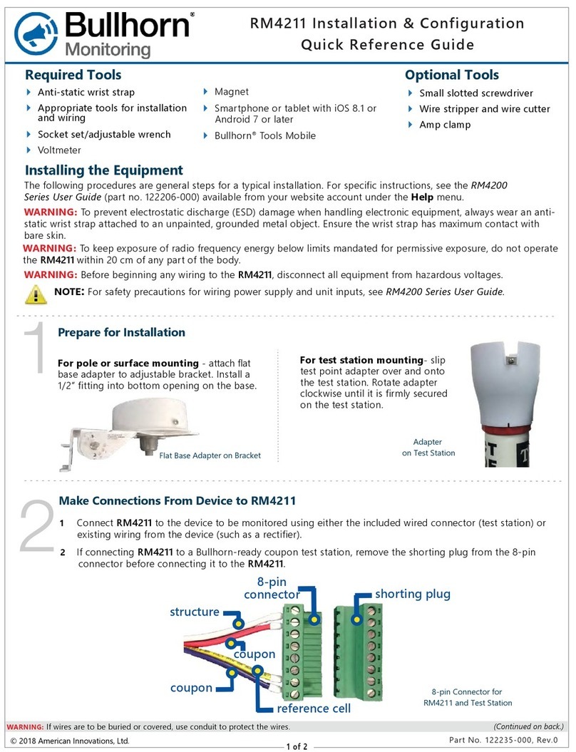
Bullhorn RM4211 User manual

Bullhorn

Bullhorn RM4211 User manual

Bullhorn RM5 I/O4 User manual

Bullhorn

Bullhorn RM5 I/O4 User manual

Bullhorn SDT16 Family Operator's manual

Bullhorn

Bullhorn SDT16 Family Operator's manual

Bullhorn RM4150 User manual

Bullhorn

Bullhorn RM4150 User manual

Bullhorn RM4200 Series User manual

Bullhorn

Bullhorn RM4200 Series User manual

Bullhorn RM4000 Series RM4010 User manual

Bullhorn

Bullhorn RM4000 Series RM4010 User manual

Bullhorn RM4150 User manual

Bullhorn

Bullhorn RM4150 User manual

Popular Measuring Instrument manuals by other brands

Powelectrics IN4MA Metron-p Technical Manual and Specifications

Powelectrics

Powelectrics IN4MA Metron-p Technical Manual and Specifications

Chopin SDmatic user manual

Chopin

Chopin SDmatic user manual

X-Rite 552 Getting started

X-Rite

X-Rite 552 Getting started

Nortel DMS-100 Series Application guide

Nortel

Nortel DMS-100 Series Application guide

Grandway FHP2A04 user guide

Grandway

Grandway FHP2A04 user guide

Pentair HAFFMANS c-DGM instruction manual

Pentair

Pentair HAFFMANS c-DGM instruction manual

AEMC 8500 user manual

AEMC

AEMC 8500 user manual

Azbil AUR355 User's Manual for Communication Functions

Azbil

Azbil AUR355 User's Manual for Communication Functions

Microtest 6630 user manual

Microtest

Microtest 6630 user manual

Atim Cloud Wireless ACW/SF8-LVL user guide

Atim Cloud Wireless

Atim Cloud Wireless ACW/SF8-LVL user guide

Delmhorst HT-3000 owner's manual

Delmhorst

Delmhorst HT-3000 owner's manual

Campbell CM 21 instruction manual

Campbell

Campbell CM 21 instruction manual

Monroe Electronics 287B Operator's manual

Monroe Electronics

Monroe Electronics 287B Operator's manual

PCE Instruments PCE-MSR 150 user manual

PCE Instruments

PCE Instruments PCE-MSR 150 user manual

Veeder-Root TLS-450PLUS Install, Setup, & Operation Manual

Veeder-Root

Veeder-Root TLS-450PLUS Install, Setup, & Operation Manual

Kestrel 3500 Delta T quick start guide

Kestrel

Kestrel 3500 Delta T quick start guide

IFR FM/AM-500 Maintenance manual

IFR

IFR FM/AM-500 Maintenance manual

EKF Lactate Scout Sport instruction manual

EKF

EKF Lactate Scout Sport instruction manual

manuals.online logo
manuals.online logoBrands
  • About & Mission
  • Contact us
  • Privacy Policy
  • Terms and Conditions

Copyright 2025 Manuals.Online. All Rights Reserved.