BB Trainer Revision 3.doc
ii
List of Figures
Figure Title Page
Figure 1 Standard Bumper Boy Ultra II
Components................................................
2
Figure 2a
Advanced Sound System............................
3
Figure 2b
Superbirds...................................................
3
Figure 2c
Camo Case. ...............................................
3
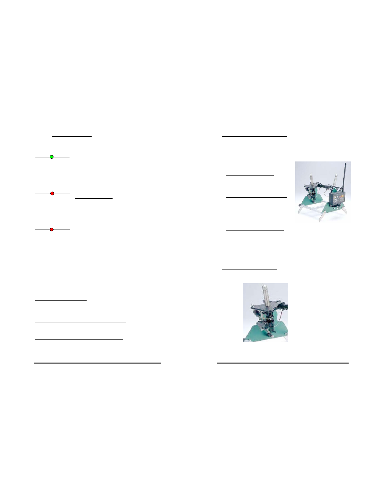
Figure 3
Image/Motion Attachment...........................
4
Figure 4
Pro Transmitter...........................................
5
Figure 5
Ultra II Receiver..........................................
9
Figure 6
Toggle Switch..............................................
9
Figure 7
Bumper Boy Ultra II Frame and
End Plates...................................................
11
Figure 8 Bumper Boy Launcher Assembly...............
11
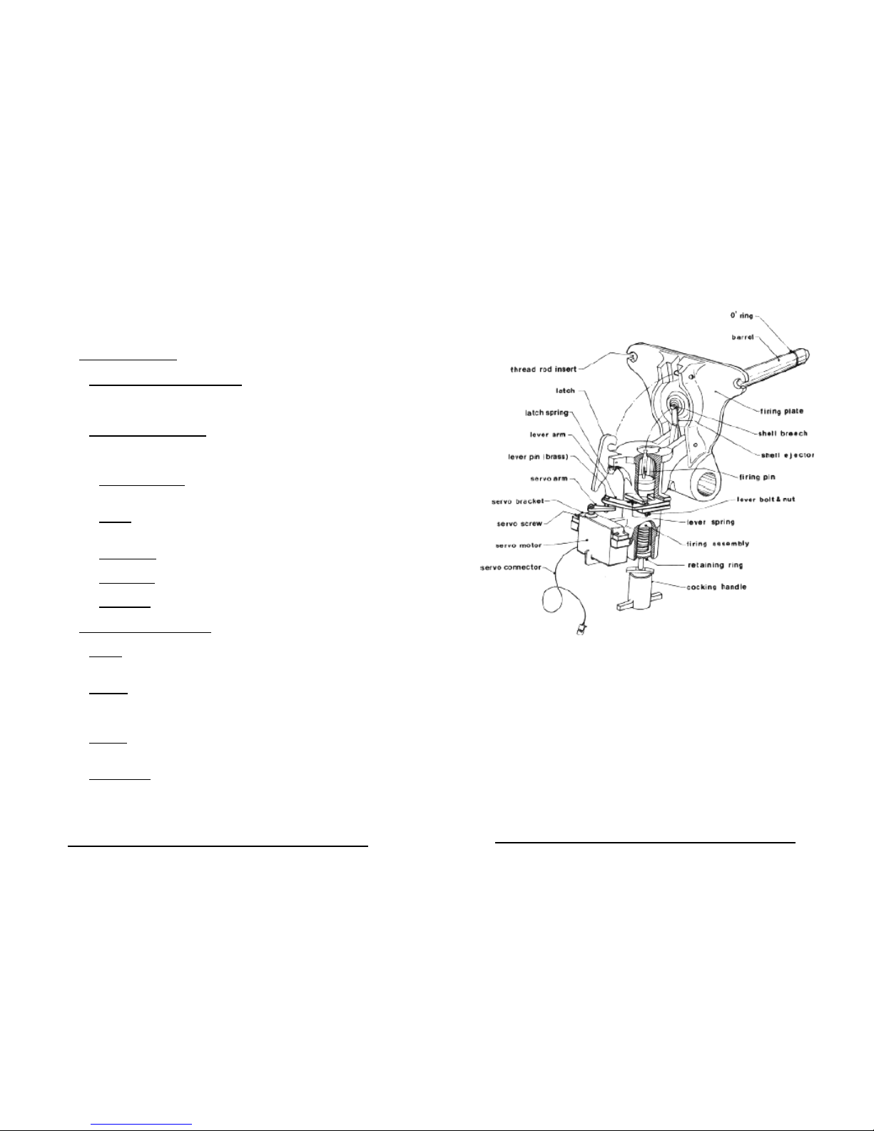
Figure 9
Launcher Assembly Cutaway Drawing …...
13
Figure 10
Advanced Speaker Installation....................
17
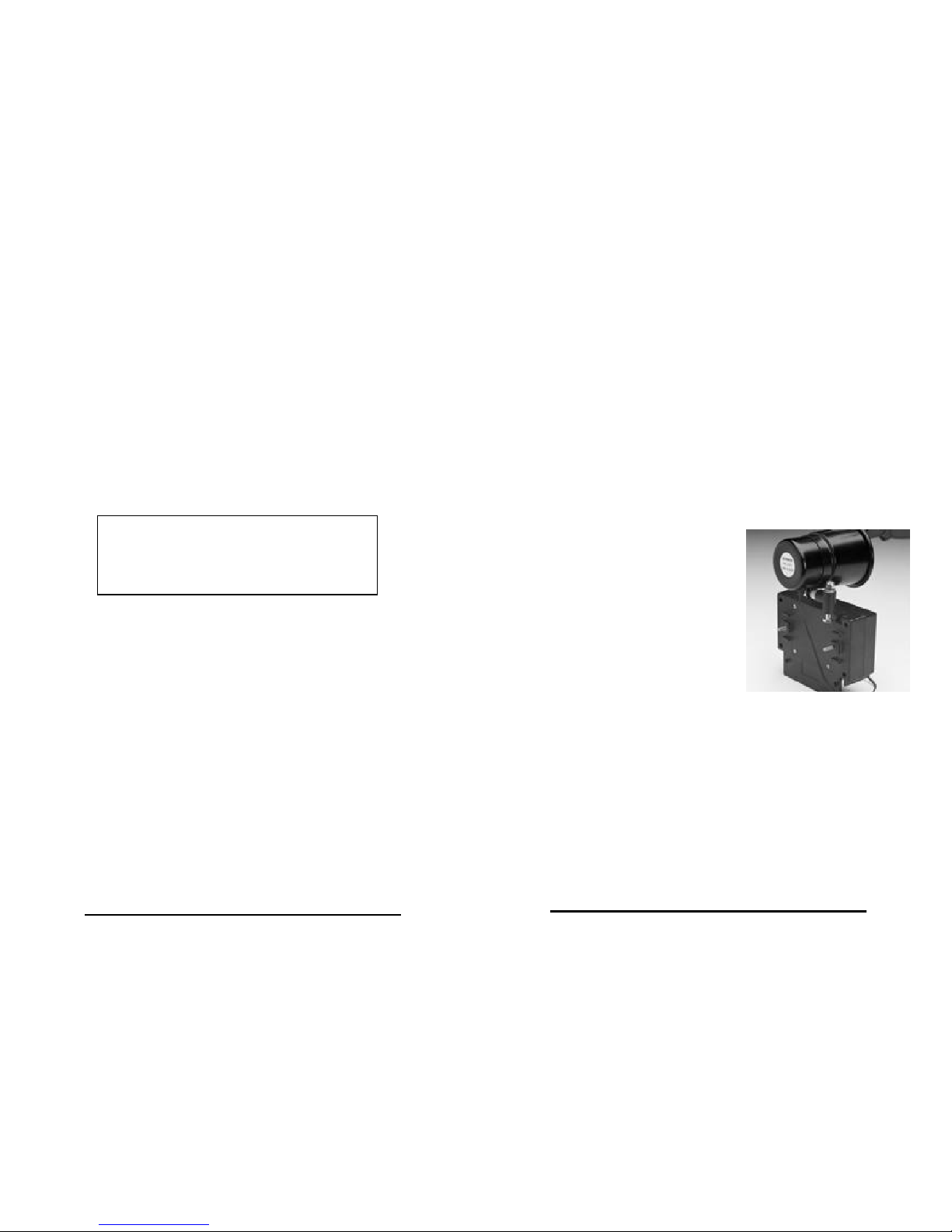
Figure 11
Bumper Assembly.......................................
18
Figure 12
Battery Charger...........................................
18
BB Trainer Revision 3.doc
1
Introduction
Whether you're a hunter, field trailer, running hunt tests,
using spaniels, pointers or retrievers, the Bumper Boy
Ultra II series will provide you with reward-based training
methods never before possible. This reward-based system
will have the largest impact on your dog's ability to
remember, retrieve, hunt, build desire and learn. This
unique training system will provide your dog with a more
enjoyable training experience, and help him learn faster.
Whether you are teaching “sit to flush” or complicated
multiple marks, you and your dog can look forward to
increased enjoyment and more effective use of time.
This sporting dog system is designed to simulate visual,
and aural dynamics of a human training assistant, and the
rapidly changing environment of a hunting experience.
This method produces better marking dogs than any
conventional training methods through use of reward-
based techniques stressed by many world-renowned
animal trainers such as Karen Pyior, PHD, an animal
behavior expert with the University of San Diego.
This manual applies to operation of all Bumper Boy Ultra II
series models.
Introduce Your Dog to Bumper Boy
Like any new training tool the dog should be introduced to
it properly. Introduce the new type of bumper; it may smell
and fly differently than the bumpers you use. In some
cases the dog thinks the flapping bumper is a live flyer and
will hunt to find a bird. This is temporary and is quickly
learned. Then introduce images, different sounds, motion
and sound of shot. This can be accomplished in normal
yard training. Now you will see your dog's eyes light up
every time you put Bumper Boy into your car.