Bungard RLM 419P User manual

RLM419p-Manual-E Page 1 / 13
Content
Introduction........................................................2
Technical Data...................................................2
EG-Declaration of Conformity..........................3
Intended Use of Machine...................................4
Safety Instructions.............................................4
Short instructions...............................................
Operating...........................................................7
Service and Maintenance.................................10
Spare part list...................................................11
Guarantee.........................................................13
Disclaimer of Warranty....................................13
Copyright.........................................................13
Bungard Elektronik GmbH & Co. KG Rilkestraße 1 51570 Windeck – Germany
Tel.: +49 2292 / 9 28 28-0, Fax: +49 2292 / 9 28 28-29 E-mail: [email protected]

RLM419p-Manual-E Page 2 / 13
Introduction
The RLM is a small but powerful dry film laminator especially made for small companies schools
research and development departments. All commercial laminates for PCB manufacture and
mould-etching part technique can be processed. Due to adjustable pressure control and ad-
justable laminating speed solder mask application is also possible without problems.
Features:
Electrically heated lamination rollers with uniform temperature distribution
Adjustable lamination pressure
Wrinkle free lamination due to separation of transport and heating rollers
patented heating roller system with sturdy ceramic heating elements
Infra-red sensors for fast and precise temperature control
Easy and fast mounting of resist rollers of nearly all coil diameters
Detachable inlet table for easy access to low resist roll
step-less adjustable laminating speed
digitally adjustable roller temperature with actual and set-point display and programmed control be-
haviour
starting 2012: Reverse drive for transport
Technical Data
Lamination width max.: 400 mm
Transport width max.: 440 mm
Lamination speed: 0.2-1.2 m/min adjustable
Resist tension: adjustable
Lamination pressure: adjustable
Temperature range: 20-145 °C (factory set max. temperature 120°C)
Power supply: 230 V 50 Hz 2 kW
Weight: 38 kg
Dimensions (W x D x H : 69 x 63 x 57 cm
Laminat mounting coil inner-
Ø
75 and 133 mm (3" and 5 ¼"); max. laminate width 400mm
Board thickness: 0.3 – 5 mm
Board size: Min 50 x 50mm; max. 450mm x endless
Bungard Elektronik GmbH & Co. KG Rilkestraße 1 51570 Windeck – Germany
Tel.: +49 2292 / 9 28 28-0, Fax: +49 2292 / 9 28 28-29 E-mail: [email protected]

RLM419p-Manual-E Page 3 / 13
EG-Declaration of Conformity
EG-Konformitätserklärung/Declaration of Conformity
Hersteller / Supplier: Bungard Elektronik GmbH & Co. KG
Rilkestraße 1
51570 Windeck Germany
Bevollmächtigte Person für die Zusammenstel-
lung der technischen Unterlagen:
Person in charge
Jürgen Bungard Geschäftsführer /general director
Rilkestraße 1
51570 Windeck Germany
Produkt: Laminator RLM 419 p
Hiermit erklären wir dass die oben beschriebenen Maschinen allen einschlägigen Bestimmungen der Ma-
schinenrichtlinie 2006/42/EG entspricht.
Die oben genannte Maschine erfüllt die Anforderungen der nachfolgend genannten Richtlinien und Nor-
men:
We hereby declare that the machines described above complies with all relevant provisions of the Ma-
chinery Directive 2006/42/EC.
The above machine meets the requirements of the following guidelines and standards:
Maschinenrichtlinie 2006/42/EG / Machinery Directive 2006/42/EC
EMV-Richtlinie 2014/30/EG / EMC Directive 2014/10830EC
Niederspannungsrichtlinie 2014/35/EG / Low Voltage Directive 2014/35/EC
DIN EN 60204-1 Sicherheit von Maschinen - Elektrische Ausrüstung von Maschinen - Teil 1: Allgemei-
ne Anforderungen / Safety of machinery - Electrical equipment of machines - Part 1: General require-
ments
DIN EN ISO 14121-1 Sicherheit von Maschinen - Risikobeurteilung - Teil 1: Leitsätze / Safety of ma-
chinery - Risk assessment - Part 1: Principles
DIN EN ISO 12100-1 Sicherheit von Maschinen - Allgemeine Gestaltungsleitsätze Risikobeurteilung
und Risikominderung / Safety of machinery - Basic concepts risk assessment and risk reduction
DIN EN 55014-1 2012-05 Elektromagnetische Verträglichkeit Anforderungen an Haushaltsgeräte
Elektrowerkzeuge und ähnliche Elektrogeräte Teil 1: Störaussendung / Electromagnetic compatibility
Requirements for household appliances electric tools and similar electrical appliances Part 1: Emission
DIN EN 55014-2-2009-06 Elektromagnetische Verträglichkeit - Anforderungen an Haushaltgeräte
Elektrowerkzeuge und ähnliche Geräte - Teil 2: Störfestigkeit - / Electromagnetic compatibility - Re-
quirements for household appliances electric tools and similar apparatus - Part 2: Immunity
Niederspannungsrichtlinie / Low Voltage Directive 2014/35/EG
Maschinenrichtlinie / Machinery Directive 2006/42/EG/37/EG
Windeck 2.3.2016
Jürgen Bungard Geschäftsführer
Bungard Elektronik GmbH & Co. KG Rilkestraße 1 51570 Windeck – Germany
Tel.: +49 2292 / 9 28 28-0, Fax: +49 2292 / 9 28 28-29 E-mail: [email protected]

RLM419p-Manual-E Page 4 / 13
Intended Use of Machine
The system is designed for laminating tenting resist or solder mask on printed circuit boards.
All other applications require our written consent or happen on full risk of the user.
The Bungard GmbH & Co. KG accepts no liability for damages incurred in non-authorised use or
application of the machine.
Safety Instructions
General
Please read the following instructions carefully and pay particular attention to information on operat-
ing safety and set up.
Keep these instructions at a safe place. It contains information which also refer for later mainten-
ance and cleaning.
The machines are intended for physical treatment of printed circuit boards.
The machines are not designed to be embedded or interconnected with other machines or systems.
They may only be used in specially equipped rooms and be operated only by qualified staff. Chil-
dren and pets are to be kept away!
Prepare preventive fire fighting measures because the machine develops heat. Do not touch the
heating rollers. Danger of burn! Don't put your fingers between heating or transport rollers.
Read the information for the laminates and observe the material safety data sheets.
Do not run the unit unattended
Transport
Only use suitable lifting and transport equipment such as forklifts or pallet lifts. Secure the machine
against sliding / tilting.
Place of installation
The machine must be standing level and around the machine there has to be sufficient space for
operation and maintenance work (approx 1m on all sides).
Do not place the unit in a location near heat sources such as radiators hot air ducts furnace and
the like.
The laminator should be installed on a table where you have access to the front and rear side of the
unit. Special care must be taken to avoid any UV light emission to the laminate. Even white light
from normal room illumination will expose the laminate. We recommend that you install yellow safe-
light tubes or at least dim the room illumination during use and cover the laminator after it has
cooled down. A good ventilation of the room or even a separate air exhaust close to the laminator
are recommended.
Do not run the machine in corroding, humid, dusty, extremely hot or explosive atmosphere.
If you do run the machine in an atmosphere as described above be aware that this happens
on your own risk and responsibility.
The operator has to provide appropriate safety precautions and equipment. We explicitly exclude
any warranty for damages resulting from running the machine in an atmospheres as described
above.
Electricity
The machine is made from certified parts according to standard practice for electrical safety. This
does not relieve the user of his duty of care when handling electrically powered devices.
Connect the device only to the designated power supply as indicated in this manual or on the ma-
chine plate.
Bungard Elektronik GmbH & Co. KG Rilkestraße 1 51570 Windeck – Germany
Tel.: +49 2292 / 9 28 28-0, Fax: +49 2292 / 9 28 28-29 E-mail: [email protected]

RLM419p-Manual-E Page 5 / 13
The red main switch disconnects the machine from the power supply. We presuppose that the
safety fuses of the circuit and the residual current circuit are provided by the building's power supply.
After completion of work the main switch should always be turned off.
Before all maintenance work on the machine (filling emptying cleaning etc.) turn off machine and
pull the plug.
To avoid the risk of electric shock do not remove the casing or open the back. There are no user
serviceable parts inside. Leave servicing to the experts! Keep this unit out of the rain and away from
moisture.
Pay attention to the warning signs on the machine. If you are not going to use the unit for some
time remove the plug from the socket.
Avoid power peaks! Make sure heating and transport are switched off before turning on the unit. Set
speed down to 0.4m/min before using the reverse transport switch. Do not quickly repeat switching
on and off.
Water connection
After work or prolonged interruption close the cock valve of the building's water supply to prevent
water damage from a possible leak in the hose.
Personal protection equipment
Do not touch heating elements and tubes. Danger of burn!
Rinsing water
The legislation generally prohibits to exceed certain maximum concentrations and quantities of cop-
per (and other heavy metals) in the waste water (usually 0.5 mg copper / liter of water). After brush-
ing the boards should not be rinsed under running water and do not dispose used rinsing water into
the sewer! Operate the rinsing water only either in a closed loop rinse or treat the rinse water with a
copper centrifuge or some special filter system. Metallic copper will be hardly removed in a ion ex -
changer system.
We recommend to use the water in the closed loop rinsing zone(s) as long as possible.
Collect used rinsing water and dispose the surplus together with the used chemicals.
Maintenance
The unit should only be maintained and repaired by qualified personnel. Never try to do more in the
way of maintenance to your unit than the operating instructions allow. Beyond that always consult
an expert for repair work.
When changing the brush you must pay attention to the correct rotating direction of the brush.
For security reason brushing rollers can only be activated if top cover is closed.
Attention: Do not start brush motor when brush is under load.
Bungard Elektronik GmbH & Co. KG Rilkestraße 1 51570 Windeck – Germany
Tel.: +49 2292 / 9 28 28-0, Fax: +49 2292 / 9 28 28-29 E-mail: [email protected]

RLM419p-Manual-E Page 6 / 13
Short instructions
Examine the machine on delivery for any visible transport
damage and if there inform shipping agent and us immedi-
ately.
Read the instructions carefully and follow the safety instruc-
tions. Read the information for the laminates and observe the
material safety data sheets. Keep this manual in a safe
place. It contains information you might later on for mainten-
ance or cleaning.
Remove the packaging and set the laminator to its destina-
tion. Unpack all the accessories (2 hand wheels power cord
4mm Allen wrench inlet table). Mount one hand wheel for
pressure adjustment at the front of the machine and the other
on the right side for manual board transport.
The photo laminates are light sensitive. For this reason the
RLM 419p is usually operated in a yellow light room. UV Fil-
ter foils and tubes can be purchased through us.
Connect the laminator to 230 V 50 Hz and do a functional
test: turn on main switch - a welcome message with version
number appears on the controller display. After some
seconds the actual and the target temperature are displayed.
Turn on the transport and check the speed of adjustment.
Turn the heating on and control that the heating rolls warm up and the actual temperature increases
in the display. Caution! Danger of burns! You can adjust the target temperature by pressing the "C"
key and then use the arrow keys to adjust the desired temperature. Press OK (the green "Enter"
key) to leave the temperature setting and store the value.
Mount either tenting resist or solder mask on both laminate rolls according to the roller schematic.
For tenting resist set pressure to 1-2 and temperature to 105°C. For solder mask set pressure to 4-5
and temperature to 115°C.
Set transport speed to 0.5 m / min and perform a laminating test.
Turn off the laminator and let the rollers cool down.
Bungard Elektronik GmbH & Co. KG Rilkestraße 1 51570 Windeck – Germany
Tel.: +49 2292 / 9 28 28-0, Fax: +49 2292 / 9 28 28-29 E-mail: [email protected]
roller schematic
Transport / Lamination rollers
Transport / Laminierwalze
Guide roller
Umlenkrolle
Take-up roller
Aufwickelrolle
Laminate coil
Laminatrolle
Take-up roller
Aufwickelrolle
Laminate coil
Laminatrolle

RLM419p-Manual-E Page 7 / 13
Operating
General
The laminator has control switches on the upper left and right
side of the housing. To the right you see the main supply switch
the drive switch "RUN" and the speed adjustment potentiometer
(4). To the left there is the digital temperature control and the
HEATER switch (5).
The transport and heater switches are illuminated when turned
on.
The thermostat has an LCD display and four buttons (6).
Heating
If you turn on the main switch a welcome message with version
number appears on the controller display. After some seconds the
actual and the target temperature are displayed. You can switch
the heating on and off with the red switch called “Heater”. To ad-
just the temperature press the red C button and use the arrow
keys up and down to adjust the desired temperature. Then press
the green Enter key. Thus the new set value is stored. A small "h"
in the display indicates that the laminator is heating. If the "h" dis-
appears then the temperature is reached and the heating
switches off. The current temperature is shown in the display.
Temperature setting proposals are about 105°C for photoresist
and 115°C for solder mask. You must determine the best setting
for your application. If the temperature is too low the resist will not
stick to the copper if it is too hot the material develops vapours
that could irritate your nose and throat and the resist could lose
its sensitivity to light or could be otherwise damaged.
The speed setting depends on the thermal conductivity of the ma-
terial you want to laminate. As a starting value for your own tests
we recommend a setting of 0.5 m/min on the potentiometer scale.
A too fast speed can show the same defects like a too low temper-
ature setting. Vice versa a too slow speed shows the same defects
as a too high temperature.
Inserting the laminate
The knob at the right side of the laminator serves for turning the
lamination rollers by hand (7). This is necessary because one im-
portant principal of construction of the RLM laminators is that the
transport rollers are separate from the lamination rollers. So the
knob serves mainly for feeding the laminate until the transport
rollers can grab it. You will need this knob only once each time you
mount a new coil.
Pressure adjustment
The knob on the lower right front is used to adjust the lamination
pressure (8). This is important as the RLM laminators can be used
for solder mask application as well. A scale to read out the setting
Bungard Elektronik GmbH & Co. KG Rilkestraße 1 51570 Windeck – Germany

RLM419p-Manual-E Page 8 / 13
can be found on the outer right side of the unit beneath the hand knob (8). In order to well press the
mask into the profile between the copper traces we recommend a setting of 4 to 5. Photoresist ap-
plication is done at a setting of 1 to 2.
Attention: Set pressure to 0 every time you stop work to avoid press marks on the rollers.
The positions 0 - 6 on the indicator scale (right hand side of the device)
correspond approximately to the following values:
Scale
posi-
tion
Roller pressure Application Scale
posi-
tion
Roller pres-
sure
Application
0 approx. 4 kg 4 approx. 12 kg Solder mask
1 approx. 6 kg Tenting resist 5 approx. 14 kg
2 approx. 8 kg 6 approx. 16 kg
3 approx. 10 kg
Mounting the laminate coils.
The following procedure is the same for photoresist and for solder mask laminate but we assume
you use only one type at a time on both the upper and lower coil.
Unpack the laminate rolls from their safelight boxes and mount them on the left flanges of the coil
holders. See the roller schematic in order to have the right sense of coil rotation. Mount the right
flanges and push them onto the coil as far as possible. The coils must not slip on the flanges. If the
coils slip on the flanges the separation foil might get between the heating rollers. Mount the coil
holders back to the laminator and put the take-up rollers back in their place.
The laminate consists of three layers. These are the outer strong
and transparent polyester cover foil the soft and sticky laminate
layer itself and a thin soft and mat plastic foil on the "inner" side of
the compound. This thin foil prevents that the laminate sticks to it-
self when it is on the coil but this foil must be removed before the
laminate goes on the board. This separation foil will wind up on the
take-up rollers.
The picture on the right shows the three layers:
1 is the polyolefin-separation foil
2 is the actual photo polymer
3 is the polyester-protection foil that you normally remove before
developing.
Pull the laminate off the lower coil for about 30 cm. Apply a piece of
adhesive tape to the upper and lower end of the laminate com-
pound and pull these "handles" to separate the thin separation foil
from the laminate.
Bungard Elektronik GmbH & Co. KG Rilkestraße 1 51570 Windeck – Germany
Tel.: +49 2292 / 9 28 28-0, Fax: +49 2292 / 9 28 28-29 E-mail: [email protected]

RLM419p-Manual-E Page 9 / 13
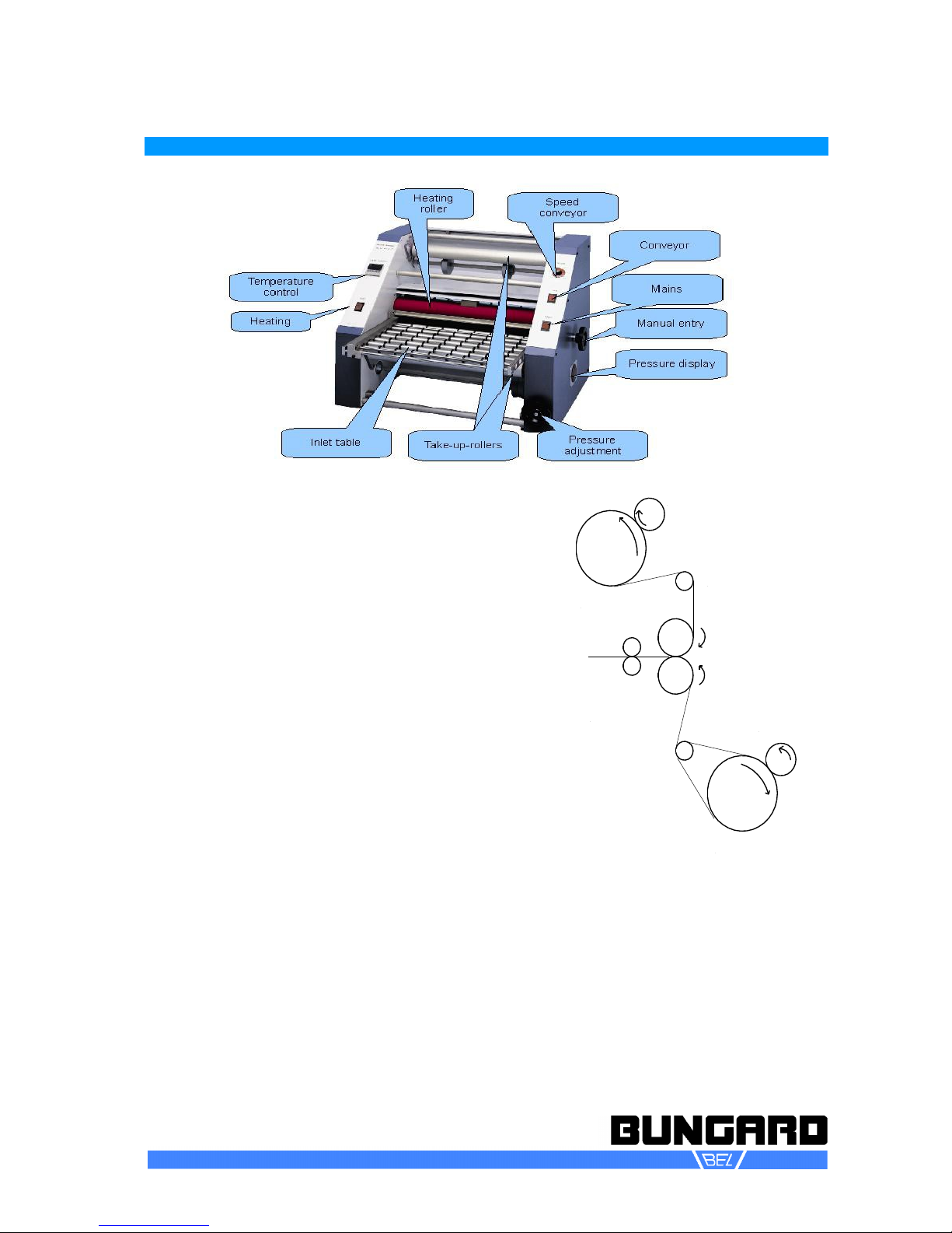
Put the take up roller back in its place on top of the laminate roller
and fix the separation foil to the take up roller by adhesive tape. Re-
peat this procedure for the upper coil with reference to the thread-
ing diagram (9). Make sure the take-up rollers are driven automatic-
ally by the rotation of the laminate coil.
For the following step you will profit from two pieces of cardboard of approx. 300 x 300 size and 1 to
2 mm thickness.
Turn the laminator main supply on.
Leave the heater and drive switch off.
Let the top laminate hang loosely over
the rollers. The protective foil faces to
the heating rollers the sticky photo
polymer faces to the operator. Take
the lower laminate and press it in
proper alignment against the top lam-
inate.
The laminate may not be sloppy or
wrinkled. You will find the wrinkles on
your board again. Now take a card-
board of 30 x 30 cm and 1 mm thick-
ness. Push it against the laminate and
further between the heating rollers (in
opposite to a pcb a cardboard is soft
and will not permanently deform the heating rollers).
Turn the hand wheel and thus promote the cardboard until you feel a firm resistance. This is the
point where the board is due to enter between the transport rollers. The transport rollers can be
seen from the back of the laminator. Set a speed of 0.5 on the scale and turn on the transport. Keep
tension on the hand wheel until you feel that the transport rollers grab the cardboard.
Stop the transport before the cardboard disappears completely between the heating rollers. Check
that upper and lower laminate run congruent. If necessary loosen alternately the left and right upper
flange and move these rollers till the laminate aligns properly.
If the laminate shows wrinkles after having shifted the flanges please insert the cardboard one
more time to enable the laminate to level out.
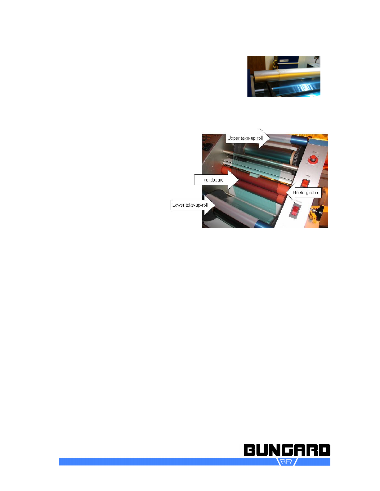
The loaded laminate will look like in picture (10):
Finally mount the inlet roller table: Lift it at its rear insert the front end in the middle of the unit until
it goes into the two lateral pins on the housing and lower the rear end until this snaps onto the pins
as well.
It is assumed that at the end of each job you leave a piece of cardboard between the lamination
rollers. This serves to keep the lamination rollers clean from molten laminate.
Laminating
Now you can start operating the machine:
Turn the heaters on. Set the desired temperature and wait until the unit has heated up. Set the pres-
sure and speed and start the transport. Let the cardboard leave the lamination rollers. Insert a PC
board through the brushes of the inlet table and push it slightly until it is taken by the lamination
rollers. If you do several PCBs at a time feed them one after the other with about 2 cm distance
between them.
Bungard Elektronik GmbH & Co. KG Rilkestraße 1 51570 Windeck – Germany
Tel.: +49 2292 / 9 28 28-0, Fax: +49 2292 / 9 28 28-29 E-mail: [email protected]
10

RLM419p-Manual-E Page 10 / 13
From the rear of the unit cut the PCBs off one after the other using a sharp knife blade. Let the
boards cool down before exposure.
The last sheet that you insert should always be the cardboard with its end still between the lamina-
tion rollers. Turn the laminator off and let it cool down. If you have yellow safelight in the room you
may leave the unit open. Otherwise you should cover the laminate coils from daylight.
Attention: Never cover a hot laminator!
Service and Maintenance
The laminator is almost maintenance free. It only needs cleaning especially if there was laminate
touching the lamination rollers. Use warm soapy water and a sponge to remove laminate rests from
the roller surface. Never use hard or sharp tools. They could damage the silicone rubber.
There are no user serviceable parts inside the left and right blue coloured side compartments.
If once laminate should have wrapped around the transport rollers you need to remove these side
compartments to gain access to the drive sprockets.
Reverse drive for transport
New starting from 2012: If the laminate has wrapped around the trans-
port rollers up to now the side walls had to be removed and the rollers
taken out. From year 2012 the RLM 419p is equipped with a "Re-
verse drive for transport button". Thus the laminate can be easily re-
moved from the laminator. The Reverse drive for transport button
should only be used for this purpose! Avoid power peaks! Set speed
down to 0.4m/min before using the reverse transport switch. Do not
quickly repeat switching on and off.
Adjusting the Roller Brake
If you happen to notice that the transport rolls do not transport the lam-
inate but slip one possible reason could be a too strong roller brake.
You can easily adjust this brake with an 4-size Allen key at the lower
and upper laminate roll. You might have to remove the left case in or-
der to fix the inner brake disk when turning the Allen key screw. If you
turn clockwise the brake impact will be stronger if you turn coun-
ter-clockwise the brake impact will be less.
At the rear of the laminator is a white steel cover. Behind this cover there is the pcb with the motor
control. You have to check the fuse which is mounted to the pcb if the laminator does not transport
the boards any more. Only exchange the fuse with a fuse having the the same values and charac -
teristics.
Bungard Elektronik GmbH & Co. KG Rilkestraße 1 51570 Windeck – Germany
Tel.: +49 2292 / 9 28 28-0, Fax: +49 2292 / 9 28 28-29 E-mail: [email protected]

RLM419p-Manual-E Page 11 / 13
Spare part list
680161 Aluminium Aufnahmeachse + 2 Jum-
bohalter für
RLM 419p dryfilm-resist holder set of
right and left PVC piece plus
hexagon axis
680162 Absaughaube f. RLM 419 P ohne
Ventilator
extraction hood for RLM 419p
without ventilator
680165 Heizwalze für Laminator RLM 419p rot heater/roller for RLM 419p laminator
680166 Zugwalze für Laminator RLM 419p
schwarz
pull roller for RLM 419p
laminator black
680167 Sechsteckige Laminataufnahmeachse
für RLM
Hexagon axis for RLM 419p laminat
fixation
680168 Auslauftisch Laminator RLM 419p rear table for RLM 419p laminator
6000 Einlauftisch Laminator RLM 419p Front table for RLM 419p laminator
680170 Gelblicht- UV-Filterfolie Breite 1 2m
Zuschnitt von
UV-filter foil yellow cut from roll
width 1 2m price
680171 Gelblicht- UV-Filterhülle für Leucht-
stoffröhren
UV-filter sleeve yellow 1 2m lenght:
680175 Entschäumer für Entwickler und Strip-
panlagen
anti-foam-agent for developing and
stripping units
680165
REP
Reparatur: Heizwalze für Laminator
RLM 419p rot
repair of heater/roller for RLM 419p
laminator
Bungard Elektronik GmbH & Co. KG Rilkestraße 1 51570 Windeck – Germany
Tel.: +49 2292 / 9 28 28-0, Fax: +49 2292 / 9 28 28-29 E-mail: [email protected]

RLM419p-Manual-E Page 12 / 13
6000 LM571911 Platine Motorsteuerung für RLM 419p Pcb motor control
6000
Bronzelager Brass bearing
Halterung für Kohlebürste Holder for coal brush
Kappe f. Kohlenbürstenhalter Cap for brush holder
Kohlebürste Brush and Spring Assembly
Isolierscheibe Washer non-metallic
Federscheibe Spring Wavy Washer
LM517842 Solid State relais Solid State relais
LM571840 Temp.controller bis 2011 Temp.controller till 2011
LM571841 Temp.sensor (Thermoelement) bis
2011
Temp.sensor (Thermoelement) till
2011
LM571601 O-Ringe Transport O-rings transport
LM571602 O-Ringe Jumbo O-rings Jumbo
699304 Schalter beleuchtet f.RLM Switch illuminated
Main switch with relay
Power cord with plug
60000 Anti-Statik-Bürste Anti static brush
60000 Anschlag für Einlauftisch Parallel stop for inlet table
60000 Vorspannungsfeder für die Heizwalzen Spring for heat rollers
60000 Seitenwand rechts mit Öffnung Druck-
verstellung
Side wall with opening pressure ad-
justment
60000 Seitenwand links Side wall left
Bungard Elektronik GmbH & Co. KG Rilkestraße 1 51570 Windeck – Germany
Tel.: +49 2292 / 9 28 28-0, Fax: +49 2292 / 9 28 28-29 E-mail: [email protected]

RLM419p-Manual-E Page 13 / 13
Guarantee
All machines are submitted before distribution to examination on function and continuous operation firm-
ness. On the machine we grant a work warranty of 12 months to our customers starting from purchase
date on accuracy in material and processing. We warrant at our choice by exchange of incorrect parts or
by repair of the machine in our house. Old parts change into our possession.
Disclaimer of arranty
Bungard GmbH & Co. KG reserves the right to change or enhance its machines or machine specifications
according to its judgement if necessary. Bungard cannot be held responsible to implement aforesaid
changes into machines sold already.
Bungard products and services are liable to the current prices and conditions which are subject to
change.
The instructions and definitions in this document are also subject to change and mark no assurance on
the part of Bungard.
This manual contains informations of the Bungard Compacta and is the translated English version.
Please regard the “Sales terms and delivery conditions”. These are available after fulfilment of the con-
tract. We don't furnish a guarantee or warranty in cause of damages at material or hurts of people be-
cause of
Incorrect use of the machine
Wrong setup installing and operating of the machine or incapable service
Use of the machine with defective safety equipment
Non-observance of the service manual in regard to transport stocking setup installation and service of
the machine
Unlicensed modifications at the machine
Incorrect or incomplete repairs
Destructive force effect at the machine in cause of foreign objects or external use of force
Use of non-original spare parts
normal wear parts.
We cannot accept subsequent claims from damage or destruction of work pieces worked on in the ma-
chine because we have no knowledge or control over the operating conditions at your site. This is valid in
a general manner also for requirements from damage to articles buildings and persons as well as the en-
vironment.
We do not warrant that the function of the machine will meet the customer's requirements or that the oper-
ation of the machine will to this regard be error free.
In no event will we be liable to the customer for any incidental consequential or indirect damages of any
kind including loss of profit and prosecution for environmental pollution even if we could have been
aware of the possibility of such damages.
All information was arranged with great care. We reserve ourselves however mistake and technical
changes without previous announcement.
Running the machine in corroding humid dusty extremely hot or explosive atmosphere happens at
the operator's own risk and responsibility.
We explicitly exclude any warranty for damages resulting from running the machine in in corroding hu-
mid dusty extremely hot or explosive atmosphere.
Copyright
© 2016 Bungard Elektronik GmbH & Co. KG
Bungard Elektronik GmbH & Co. KG Rilkestraße 1 51570 Windeck – Germany
Tel.: +49 2292 / 9 28 28-0, Fax: +49 2292 / 9 28 28-29 E-mail: [email protected]
Other manuals for RLM 419P
1
Table of contents
Other Bungard Laminator manuals