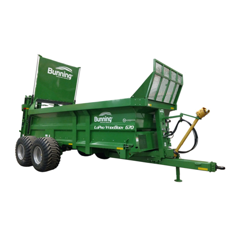
BUNNING 180 User manual

180 - 230
Widebody Manure Spreader
Owners Manual


LOWLANDER180 & 230 WIDEBODY MANURE SPREADER – INSTRUCTION & SPARES MANUAL
Page
1
Thank you for buying a Bunning spreader. For your Bunning guarantee please fill in the form below
andreturn it to Norwood Sales Inc.
Customer Name
Zip Code
Telephone
Fax
Email
Machine ID Number
Date of delivery
LOWLANDER WARRANTY REGISTRATION FORM
Company Name
ID No. Exa mpl e 01/01/9999/U/MSL180
Dealer
Address
Important Data Protection Information.
We or ourbusiness partners may contract you by mail, telephone, e-mail or other electronic messaging services with offers of goods and services or
information that may be of interest to you.
By providing uswith yourtelephone number or e-mail address you consent to being contacted by these methods.
If you do not wish to receive marketing information by these methods from GT Bunning or our business partners please tick this box.
Return Address
Norwood Sales Inc
11202 38th St S
Horace, ND 58047

LOWLANDER180 & 230 WIDEBODY MANURE SPREADER – INSTRUCTION & SPARES MANUAL
Page
2
11
Grease all points ifnecessary.(see
manual).
10
Check condition of all cylinders & pins.
18
Ensure tyre pressures are correct for speed &
load.
16
Check oil level offloor drive gearbox and
auger drive gearbox.
4
Locate, identify & explain spreader to
towing vehicle air ,hydraulic and electric
connectors.
STRUCTURE
9
Check condition of body, drawbar & augers
15
Check air system hose condition and
connectors. (Option).
WHEELS & TYRES
17
Check condition of tyres.
6
Explain how to cut the PTOguard to size
and where to fit the safety chains.
BRAKING
Check condition of cabling & 7 pin connector.
HYDRAULICS & PNUEMATICS
14
Check hydraulic hose condition especially
brake hoses & connectors.
3
Explain the functions of the machine.
Check hydraulic cylinder for leaks and
damage.
SIGNATURE
DATE:
19
Check wheel nut torque. (Check daily for first
week ofuse)
7
Check operation of parking brake.
8
Check operation of service brake.
OPERATOR
DEALER
I have received a copy of the instruction & spares manual and
understand the method of operation, the safety requirements
and the maintenance methods.
I have given basic instruction in the method of operation, the
position of safety stickers and methods of maintenance, and
ensured that the owner/operator is in possession of the
Manual.
Pre-Delivery Inspection sheet
The purpose of this document is to ensure that the operator, hirer or owner is fully appraised of all safey
guidelines and operating and maintenance methods before taking possession of the machine.
Bunning Lowlander Widebody
5
LIGHTING
12
Check operation of lights
13
1
2
Draw attention to the safety decals
located on the machine.
GENERAL
Ensure the operator receives a copy ofthe
instruction & spares manual.

LOWLANDER180 & 230 WIDEBODY MANURE SPREADER – INSTRUCTION & SPARES MANUAL
Page
3
CHASSIS SERIAL NUMBER................................................................................
SECTION & CONTENTS PAGE
Preface 7
How to use this manual 7
Operating on public roads 7
Introduction 8
Disposal 8
EC Declaration of Conformity 9
Machine over view 10
1. OPERATING INSTRUCTIONS
1.1 Hitching to tractor. 11
1.2 Coupling of hydraulic hoses. 12
1.3 Hand brake. 13
1.4 Brake adjustment. 13
1.5 Floor adjustment. 13
1.6 Method of operation. 13
1.7 Slurry Door. 13
1.8 Installation and use of detachable spinning deck. 14
1.9 Horizontal beater operation. 16
2. MAINTENANCE
2.1 Lubrication of spreader. 17
2.2 Servicing intervals. 17
2.3 Amount of oil required to fill gearboxes. 20
2.4 Service record 21
2.5 Shear bolt protection. 22
2.6 Grease points 22
DRAWINGS AND PARTS LISTS
3. FLOOR DRIVE
3.1 Hydraulic circuit for floor drive. 23
3.2 Floor control unit. 24
3.3 Floor drive relief valves. 26
3.4 Floor drive gearbox B3122. 27
3.5 Rear floor shaft assembly. 29
3.6 Front shaft and chains. 31

LOWLANDER180 & 230 WIDEBODY MANURE SPREADER – INSTRUCTION & SPARES MANUAL
Page
4
4. AUGERS & DRIVES
4.1 Shredding augers. 32
4.2 Horizontal beater with spinning discs. 34
4.3 Gearbox 1000/350 B3180. 37
4.4 Gearbox Spinner deck – through drive 1000/350 B3185. 39
4.5 Gearbox Detachable Spinner deck 1000/520 B3190. 41
4.6 Transverse gearbox horizontal beaters B3183. 43
4.7 Transverse drive assembly horizontal beaters. 45
5.0 P.T.O AND TRANSMISSION
5.1 Transmission model. 46
5.2 Transmission Horizontal beater. 46
5.3 Problems and possible solutions. 47
5.4 Waltersheid wide angle PTO. 49
5.5 Walterscheid torque limiter complete 6 spline W/A 49
5.6 Comer T60 underbody shaft 50
5.7 Walterschied PTO shaft 51
5.8 Walterschied W/A PTO shaft Part No. 43102 52
5.9 Comer PTO guard safety chain fixing. 54
5.10 PTO stowage. 56
6. BRAKE & AXLE ARRANGEMENTS
6.1 Brake arrangment EUR 1510 414S – 180. 57
6.2 Axle hub and bearing parts 180. 59
6.3 Tandem axle hub parts EUR 1130 axle 230. 61
6.4 Tandem axle brake parts EUR1130 axle 230. 62
6.5 Tandem axle 230. 63
6.6 Hydraulic brake ram assembly 35mm bore. 64
6.7 Hydraulic brake ram assembly 25mm bore. 65
6.8 Hydraulic brake circuit – single axle. 66
6.9 Hydraulic brake circuit - tandem axles. 67

LOWLANDER180 & 230 WIDEBODY MANURE SPREADER – INSTRUCTION & SPARES MANUAL
Page
5
7. AXLES & SPRUNG DRAWBAR
Safety notice. 68
General information. 69
Axle, maintenance and adjustment. 70
Sprung drawbar spring information 81
Minimum program of maintenance sheet. 82
8. TYRES AND WHEELS
8.1 Tyre and wheel maintenance. 83
8.2 Tyre pressure settings. 84
8.3 Wheel type and torque settings. 87
9. OPTIONS
9.1 Sprung drawbar. 88
9.2 Guillotine slurry door. 89
9.3 Guillotine slurry door horizontal beaters. 90
9.4 Guillotine slurry door hydraulic circuit drawing. 91
9.5 Support Leg. 92
9.6 Detachable spinner deck kit. 93
9.7 Simple canopy 95
9.8 Auto rear lamp covers 96
9.9 Body rubber seals 97
9.10 Weigh cell spares 98
10. ELECTRICS
10.1 Wiring for 12v 7 pin plug. 99
10.2 Rear lamps. 100
10.3 Marker lamps. 100

LOWLANDER180 & 230 WIDEBODY MANURE SPREADER – INSTRUCTION & SPARES MANUAL
Page
6
11. HEALTH AND SAFETY & POTENTIAL HAZARDS
11.1 Hazardous machinery warning. 101
11.2 Loss of control. 101
11.3 Operation around bystanders. 101
11.4 Hydraulic fluid penetration or burning. 101
11.5 Electrocution. 101
11.6 Body entry. 101
11.7 Coupling / decoupling. 101
11.8 Machinery start up. 102
11.9 Machinery shut down. 103
11.10 Additional driver protection. 102
11.11 PTO Connection and guarding. 102
11.12 Personal protective equipment 102
11.13 Safety decal location. 102
11.14 Operating hazard area 103
11.15 Warnings 104
12. WARRANTY 104
13. IMPORTANT INFORMATION 105
14. NOTES 106
15. IDENTIFICATION PLATE 107
16. TECHNICAL DATA & SPECIFICATIONS 109
17. MACHINE DIMENSIONS 109

LOWLANDER180 & 230 WIDEBODY MANURE SPREADER – INSTRUCTION & SPARES MANUAL
Page
7
PREFACE
The instructions in the manual must be read carefully and followed by all persons concerned with the operation,
maintenance, repair or inspection of this machine in order to prevent accidents.
Read especially sections relating to safety, operating instructions and maintenance.
The use of spare parts, accessories and additional equipment which is not originally manufactured checked and
release by GT Bunning Ltd can have a negative effect on specific design features of the machine and on its
operability. This may impair its operating safety, as well as safety at work for the operator and could invalidate
warranty.
GT Bunning will in no way be liable for damage or personal injury caused by the use of other than original GT Bunning
parts, accessories and additional equipment.
Technical specifications, dimensions and weights are given with the usual tolerances (+ or – 2%).
GT Bunning Ltd operates a policy of continual improvement; as such some items in this manual may differ slightly
from that of your machine. GT Bunning reserves the right to make changes to the machine or manual without
notice. If in any doubt regarding any aspect of the design or operation of this machine contact GT Bunning Ltd or
your GT Bunning Ltd agent for clarification.
HOW TO USE THIS MANUAL
The manual contains sections that cover all of the following, Safety, Operating instructions, Maintenance,
Specifications and Technical data. Refer to the contents pages for the relevant page number.
Before use of the machine familiarise yourself with the manual and its contents
The machine should only be operated, serviced and repaired by persons who are familiar with the machine and
who have read and understood this manual, and are informed of the risks.
This manual should stay with the machine/operator at all times.
OPERATING ON PUBLIC ROADS
Before operating on public roads the spreader must be correctly connected to the towing vehicle, the lights must
be connected and function of the lighting equipment must be checked. The braking system of the spreader must
be correctly connected to the towing vehicle, check for correct operation.

LOWLANDER180 & 230 WIDEBODY MANURE SPREADER – INSTRUCTION & SPARES MANUAL
Page
8
INTRODUCTION
This manual provides information on the use, adjustment and servicing of the GT Bunning range of Lowlander
spreader.
Following the advice on the correct maintenance and servicing procedures will ensure maximum performance and
a long service life of your machine.
Failure to carry out maintenance work correctly, or incorrect operation will result in poor machine efficiency and
loss of valuable time.
By ensuring the correct operation, and by carrying out maintenance and service work with care, you will be able to
make full use of the technical knowledge and the experience with which your Lowlander spreader was originally
designed.
DISPOSAL
Upon completion of the useful life of the machine, all parts can be disposed of at a suitable waste disposal facility.
Care must be taken if oxy-acetylene cutting equipment is to be used.
The wheels and tyres, hydraulic cylinders, valves and hoses must be removed before using cutting equipment.
Oil must be drained collected and disposed of in accordance with current legislation.
Electrical components must be disposed of in accordance with the relevant legislation.

LOWLANDER180 & 230 WIDEBODY MANURE SPREADER – INSTRUCTION & SPARES MANUAL
Page
9
G.T.BUNNING & SONS LIMITED
SPREADERS, TRAILERS & TANKS
Telephone: 01362 860352 Registered Office:
Fax: 01362 860930 Smithy House,
TheGreen
E-mail: sales@gtbunning.co.uk Gressenhall, Dereham
www.gtbunning.co.uk Norfolk, NR20 4DT
EC MACHINERY DIRECTIVE
2006/42/EC
DECLARATION OF CONFORMITY
We hereby ceritify that the machinery stipulated below complies with all the relevant provisions of the EC
Machinery Directive 2000/42/EC & regulations adopting the Directive.
Modifications to this machine without prior written approval from the undersigned will render the declaration
null & void.
Machine Description: Unbalanced trailer for the
carriage & application of manure
Machine Type: Agricultural manure spreader
Model: Lowlander MSL
Serial Number: / / /U/MSL
Standards used.
BS ISO 4251-1:2005+A1:2012, BS EN ISO 12100-1:2010, BS EN ISO 4254-1:2009, BS EN 690: 1994+A1:2009,
BS EN 15811: 2009, BS EN ISO 13857:2008, BS EN 349:1993+A1:2008, BS EN 12965:2003+A2:2009,
BS EN 953:1997+A1:2009, BS EN ISO 5674:2009, BS ISO 4413:2010.
Signed Date :
Name: Greg Shepherd Position: Joint Managing Director

LOWLANDER180 & 230 WIDEBODY MANURE SPREADER – INSTRUCTION & SPARES MANUAL
Page
10
MACHINE OVER VIEW
KEY QTY DESCRIPTION
1 1 BODY
2 1 DRAWBAR
3 1 STONE GUARD
4 1 FRONT PILLAR
5 1 PTO DRIVE LINE
6 1 FINGER GUARD
7 1 SUPPORT LEG
8 1 LADDER
9 2 WHEEL & TYRE ASSEMBLY
10 1AUGER GEARBOX
11 1FLOOR DRIVE GEARBOX, MOTOR AND VALVE
12 2AUGER
13 2LAMP ASSEMBLY
14 1AXLE

LOWLANDER180 & 230 WIDEBODY MANURE SPREADER – INSTRUCTION & SPARES MANUAL
Page
11
1. OPERATING INSTRUCTIONS
The intended purpose of the vehicle is to tow and spread manure and other materials.
1.1 Hitching to tractor.
Attach spreader to pick-up hook or static hitch stub. Do not attach to swinging drawbar or pick-up hook
in extended position.
Remove screwjack from drawbar (if fitted) and locate in transport position provided at the front of
spreader.
Turn off the tractor and remove key before fitting PTO.
Slide the tractor end of the PTO shaft out and fit to the tractor PTO. Lay the two halves of the PTO shaft
alongside one another and mark the required lengths, allowing for turning. Maximum pull out of 12 inches
of the 2 shafts. Cut to size and clean burrs at each end of shaft KEEP SHAFT SLIDING SURFACES GREASED.
Attach chains fitted to PTO guard (to prevent rotation of guard) to suitable point on the tractor and hole
provided on metal cover over PTO shaft on spreader. Ensure that the spring loaded pins in splined yokes
are fully locked in position. Always disengage the PTO when turning sharply to avoid damage to shafts
universal joints. Where a wide angle PTO is fitted attach this end to the tractor. Please refer to the DVD
for more information.

LOWLANDER180 & 230 WIDEBODY MANURE SPREADER – INSTRUCTION & SPARES MANUAL
Page
12
1.2 Coupling of hydraulic hoses.
Fit the two hoses for the floor drive hydraulic motor (one to feed and one for return) to double spool valve
on tractor. Choose position of spool lever for ease of control to obtain floor movement to rear. Reversing
of floor is done by selecting the opposite position of the hydraulic control lever. Universal quick release
probes are fitted as standard to hose ends. Mark hose as required to assist in the future coupling for
correct position of feed and return. When a slurry door is fitted connect the hydraulic hoses to a double
spool valve and select the hose positions to suit the operator to open and close the door.
Fit hydrualic brake hose to trailer brake valve on tractor (male fitting).
A universal female brake coupling is fitted as standard to the hose ends.
N.B CHECK DIRECTION OF FLOOR BEFORE LOADING.
Do not run floor in reverse with full load. Speed of floor in reverse is at MAXIMUM.
Only reverse floor for a few seconds.
Ensure the braking system is connected and that it functions correctly before moving.
FLOOR PRESSURE
FLOOR RETURN
SLURRY DOOR OPEN
SLURRY DOOR CLOSE
BRAKES

LOWLANDER180 & 230 WIDEBODY MANURE SPREADER – INSTRUCTION & SPARES MANUAL
Page
13
1.3 Hand brake.
The handbrake is a multi-stroke ratchet type. To apply the handbrake give the handle short pumps (a
clicking of the ratchet will be heard) until resistance occurs and subsequent tightening of the cable. To
release the handbrake give the handle one sharp movement in the opposite direction. This releases the
ratchet mechanism.
1.4 Brake adjustment.
Brake adjustment is carried out at the hydraulic brake ram unit fitted to each wheel axle giving
independent adjustment to each wheel. To adjust, jack up the spreader, slacken the locknut in the set
screw and turn the set screw clockwise. (See section 7)
BEWARE NOT TO OVER ADJUST. Make sure the wheel can rotate freely.
1.5 Floor adjustment.
When adjusting floor chains ensure that the adjustment is carried out equally to both sides.
DO NOT ALLOW THE CHAINS TO BECOME TOO SLACK.
ADJUST CHAINS AFTER A FEW LOADS.
KEEP CHAINS ADJUSTED CORRECTLY AT ALL TIMES, A GUIDE IS TO BE ABLE TO SEE A WHOLE LINK BELOW
FRONT BOTTOM EDGE OF SPREADER i.e. FROM CENTRE TO FRONT.
Reverse floor
The floor should only be reversed for very short periods, to clear the augers.
Do not reverse if the floor chain is slack, tighten floor chain first.
1.6 Method of operation.
1) Select speed of floor required on control valve.
2) Engage PTO to power the rear augers – tractor engine revs low.
3) Raise slurry door fitted.
4) Engage spool valve to power floor to rear.
1.7 Slurry Door
As the load height reduces lower the slurry door to cover the augers. This will help prevent foreign
objects being thrown forward.

LOWLANDER180 & 230 WIDEBODY MANURE SPREADER – INSTRUCTION & SPARES MANUAL
Page
14
1.8 INSTALLATION AND GENERAL USE OF DETACHABLE SPINNER DECK
GENERAL USE
The detachable spinner deck is designed purely for wider spread patterns and low application rates of
between 1 and 3 ton per acre. It must NEVER be used to spread long straw based material or heavy
applications beyond 5 ton per acre.
INSTALLATION
When fitting or removing the spinner deck assembly great care must be taken not to endanger an assistant
in any way, especially when raising or lowering the unit. Persons must not be put at risk.
Before making any adjustments, fitting or removing attachments, the tractor that the spreader is attached
to must be switched off and the key removed.
FITTING THE SPINNER DECK
1 Remove guard from output spigots of the auger gearbox.
2Slide one half of ‘flexi coupling’ onto the shaft, through shaft of spinner gearbox.
3 Slide other half of the ‘flexi coupling’ on the input spigot of the spinner gearbox.
4 Using approved lifting apparatus lift the complete spinner deck assembly using lower lifting eye on
canopy (ensure bolt & nuts No. 20/20 and 16/18 are securely in place).
5 Offer the assembly to rear of the machine and lower into position. Firstly locate the ‘bucket hooks’
of deck into clevises at the top rear corners of the spreader.
6 Hinge hook bolt No. 14 into anchors and tighten.
7 Fit and tighten 4 bolts to join the two halves of the flexi coupling.
8 The machine is now ready for use with the spinner deck.
Flexi coupling
Bucket hooks
Cattle ramp fastener

LOWLANDER180 & 230 WIDEBODY MANURE SPREADER – INSTRUCTION & SPARES MANUAL
Page
15
REMOVING THE SPINNER DECK
1 Clean all material from spinners and decks.
2 Remove 4 bolts from the flexi coupling.
3 Loosen hook bolts No. 14 and hinge back to clear anchors.
4 Using approved lifting apparatus lift from lower lifting eye on the canopy firstly pulling the bottom
of the deck assembly away from rear of spreader to the clear auger blades.
5Lift the assembly clear of the spreader and stand on level ground with the front of the assembly
close to, or against a wall or stable object.
6 Fit the shaft cover to the output spigot of the spreader beater gearbox.
7 The machine is now ready for use without spinner deck.
ADJUSTMENT OF CANOPY & BLADES
For the best results
1 Fix the canopy on the inner positions for light materials i.e. Poultry manure.
2For heavy material i.e. slurry or sludge adjust canopy out as far as possible so as not to deposit
material beyond the deck into gaps between the discs.
3 To increase the width of the spread pattern adjust the angle of blades forward on the disc.
4 If the spread pattern is light immediately behind the machine adjust the angle of the blades back.
5 It is possible to achieve an even spread by adjusting blades as opposing pairs. i.e Blade 1 and 3 in
position 3 and blade 2 and 4 in position 1.
LEFT HAND SPINNER
DIRECTION OF SPIN

LOWLANDER180 & 230 WIDEBODY MANURE SPREADER – INSTRUCTION & SPARES MANUAL
Page
16
1.9 OPERATING INSTRUCTIONS FOR HORIZONTAL BEATERS
General use
The horizontal beater with spinner discs is designed primarily for wider spread patterns and lower
application rates for product such as chicken and turkey manure, however long straw based materials can
be spread effectively. It must be expected that application rates maybe slower than a vertical auger
spreader.
Adjustments for spread patterns
The position of the lower section of rear canopy and the angle of the blades on the discs will affect the
spread pattern and width.
Select a hole position that places the rubber strip over the middle of the discs for a lighter application
rates and wider widths. Adjust the hole position to move the rubber strip rearwards for higher application
rates e.g. for straw based materials. Excessive rearward adjustment will cause the material to miss the
discs and hit the ground without being spread.
Each spinning disc is supplied with 2 blades on and the others loose; it has been proven that many
materials are spread more effectively with just 2 blades per disc.
1 To increase the width of the spread pattern adjust the angle of blades forward on the disc.
2 If the spread pattern is light immediately behind the machine adjust the angle of the blades back.
3 It is possible to achieve an even spread by adjusting the blades, as opposing pairs. i.e. Blade 1
and 3 in position 3 and blade 2 and 4 in position 1.
4 When adjusting angle use the 2nd set of holes on the blade to keep the tip of the blade on the
edge of the disc
Change angle of lower
canopy here.
Rubber strip pointing
at the centre of
spinning discs.

LOWLANDER180 & 230 WIDEBODY MANURE SPREADER – INSTRUCTION & SPARES MANUAL
Page
17
2. MAINTENANCE
2.1 Lubrication of spreader.
DAILY GREASE Front and rear floor shaft
Overrun clutch to front of main ‘T’ gearbox
Hitch eye
WEEKLY GREASE All sealed bearing – 1/2 pump of grease gun maximum.
TAKE CARE NOT TO DAMAGE GREASE SEAL BY OVERGREASING
Sliding tube of PTO shaft.
PTO universal joints – Follow manufacturer’s instructions.
Screwjack top (when fitted)
Shearbolt bush
MONTHLY Check gearbox oil levels
ANNUALLY Change oil to all gearboxes
TYPE OF LUBRICATION GREASE Multi purpose
GEARBOXES EP90
2.2 Servicing intervals
The period recommended is based on normal operating conditions. Severe or unusual conditions may require
more frequent lubrication or oil changes.
IMPORTANT: ENSURE CV JOINT IS GREASED BEFORE FIRST USE!
TAKE CARE NOT TO DAMAGE SEALS BY OVERGREASING.
DAILY (8 HRS)
1. Check for hydraulic fluid leaks and damaged hoses.
2. Grease Front and Rear floor chain shaft bearings.
a. Front shaft.
• Remove front Finger Guard to access bearings.

LOWLANDER180 & 230 WIDEBODY MANURE SPREADER – INSTRUCTION & SPARES MANUAL
Page
18
b. Rear Shaft.
• Grease both left and right bearings.
3. Grease the Overrun Clutch to front of the auger gearbox.
WEEKLY (40 HRS)
1. Check wheel nuts. Re-torque as needed.
2. Grease all sealed bearings
a. Driveline hanger bearings (2 or 3 depending on model).
b. Top auger bearings (Grease nipples access provided on right turret).
3. Grease the telescoping section of the PTO shaft.
This manual suits for next models
1
Table of contents
Other BUNNING Spreader manuals
Popular Spreader manuals by other brands

SPYKER
SPYKER BCS25 Operator's manual

Gandy
Gandy 24H12 Operator's manual

Roto-Mix
Roto-Mix Roto-Spread 532-16 Owner's Manual, Installation Instructions and Parts

Sam
Sam 6 TONNE SINGLE AXLE Instructions and parts manual

Meyer
Meyer Diamond Edge 41685 Assembly instructions

Tube-Line
Tube-Line NITRO 575RS Operator's manual