SET UP
CAUTION! Ensure the 3 phase supply is disconnected before proceeding.
Connect the 3 phase supply 400VAC with Neutral and Earth to the terminals marked ‘L1, L2, L3 Neutral and
Earth’ ensuring the phase rotation is correct, so connect the leads like this:
Brown (L1) Black (L2) Grey (L3)
Connect the 3 X 2KW Lamp Loads to the terminals marked ‘T1, T2, T3, star connected to Neutral’.
Configure the oscilloscope to measure AC mains voltage and connect one of the scope’s channels across a
lamp load.
Connect the HMI unit to the main controller using four core twisted cable to the terminals marked A, B, 24V and
COM on both units.
Set DIP SW1 to 1000 this sets the controller to operate on channels 1,2 and 3 using either the handset or HMI
unit, see Table A and B on the right hand side of the control pcb.
Test
CAUTION! Beware of hazardous voltages while testing!
Switch on the 3 phase supply to the BHC6003-ER and verify the green ‘POWER’ LED is lit and the HMI digits
are lit. When the main power controller is sending data back to the HMI unit the red ‘STATUS’ LED will pulse.
Using the HMI push buttons step through the channels and power levels indicated by the UP and DOWN arrows
on the fascia.
Leave all three channels powered up to three different output levels, press the ALL ON/OFF button once this will
turn all three channels off, press the button again this will reinstate the outputs to the power levels previously
selected.
Pressing the CH OFF button turns the indicated channel off, to turn it on again use the POWER up button.
Switch off the mains power to the controller and wait a few seconds then re-apply the mains power, all the
controller outputs will be in the off state, when the ALL ON/OFF button is pressed the previously selected
channels and output levels will be re-instated.
These tests can also be done using the handset, with the handset the channels can be selected individually by
pressing the buttons numbered 1, 2 and 3.
With the DIP switch code set to 1000 the HMI unit will scroll around channels 1 2 and 3, with the code set to
1100 the HMI unit will display and scroll around channels 4, 5 and 6. With the code set to 1110 channels 7, 8
and 9 will be activated in the same manner.
Next set the controller to three phase three channel tracking where all three outputs are controlled as one
channel this mode is selected by setting the DIP switch code to 0001.
With DIP switch code set to 0001 channel 1 will be selected and displayed on the HMI unit. Adjusting the
POWER up and down buttons will result in all three phases having the same output levels through 0 to F.
Check that the HMI unit does not respond to any other channel selection.
After testing return the DIP SW1 code to 1000.
Switch off the 3 phase 400VAC mains supply and disconnect the BHC6003-ER - the test is now complete.
INTRODUCTION
The BHC6003ER is a microprocessor based power controller which has been designed to offer variable control for 3
separate 2kW loads from a 3-phase supply. The units have been manufactured to offer easy installation and
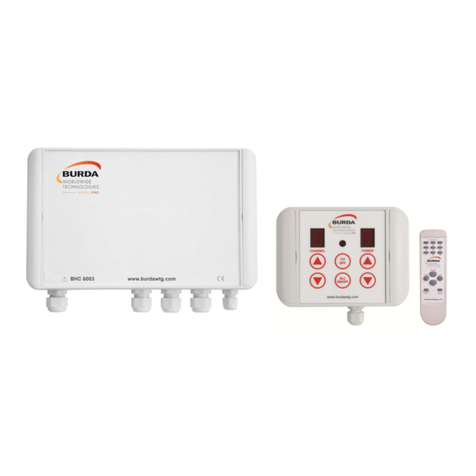
functionality. The system consists of three elements: A HMI unit 1(Human Machine Interface) which is wired via a
low voltage 4-core cable to the main power unit 2, this then allows the operator to vary the output from off and 30% to
100% via a 10 step output. All the HMI functions are also available via the infra-red remote control handset 3.
Additionally you can switch off all the channels or individual channels as required via the HMI. The main power unit
which has been built into a smart robust IP65 rated enclosure can be mounted remotely from the HMI unit. The main
power unit can also link up to an additional 2 power units allowing you to control 9 individual 2kW outputs or 8 other
power units allowing you to control 9 power units (the 3 outputs within each power unit will increase at the same level
in this configuration) up to 54kW in total (2kW x3 outputs x 9 Power units) Note: see installation for output options.
•HMI BUTTONS
CHANNEL + Increment channel selection (1 to 9)
CHANNEL - Decrement channel Selection (1 to 9)
CHANNEL OFF Switch off Current Channel
ALL ON/OFF Switch ON or OFF all channels (Toggle)
POWER + Increment Current Channel Power Level (0,1,2,3,4,5,6,7,8,9,F)
POWER - Decrement Current Channel Power Level (0,1,2,3,4,5,6,7,8,9,F)
•REMOTE HANDSET BUTTONS
CHANNEL Buttons 1 to 9 for Channel Selection
CHANNEL+ Increment channel selection (1 to 9)
CHANNEL- Decrement channel Selection (1 to 9)
CHANNEL OFF Switch off Current Channel
ALL ON/OFF Switch ON or OFF all channels (Toggle)
POWER + Increase output level from 0 to F
POWER - Decrease output level from F to 0
•POWER UNIT CONNECTIONS
SUPPLY INPUT 3 Phase Supply (400V AC +/-10%) (L1,L2,L3,N,E)
LOAD OUTPUTS Heater Terminations (T1,N,Earth),(T2,N,Earth),(T3,N,Earth)
SW1 4 Way DIL Switch for Channel Configuration Options
HMI Communication RS485 communication Terminals A & B
HMI Low Voltage Power Terminals +24V DC & COM
SUPPLY GREEN LED Power unit supply present
STATUS RED LED Serial Data Received Acknowledgement
APPLICATIONS
Any application were high inrush current is an issue or control is required. Typical use is for Infra Red Heating lamps
and Garden lighting
FEATURES
Soft Start Up to 30% extended life of Lamp
Variable Control Ability to find comfort level
Remote Control Ease of use
HMI Vary output and switch channels on and off
IP Rated HMI and BHC6003-ER are IP65 rated, suitable for outdoor installation
Additional Channels Multiple units can be added and function from 1 off HMI and Remote Handset


