Burdick Atria 3000 User manual

Atria™ 3000
Electrocardiograph
Part No. 070-1133-00 Rev. A
Service Manual

TO RESPONSIBLE SERVICE PERSONNEL:
The contents of this document are not binding. If any significant differences
between the product and this document are encountered regarding service
work, contact Quinton Cardiology, Inc. for further information.
Quinton Cardiology, Inc. recommends the use of authorized Quinton
Cardiology personnel for the maintenance and repair of all Burdick equipment.
Quinton Cardiology, Inc. cannot warrant the operation of the equipment if
other than Burdick genuine replacement or exchange parts are used in the
service or repair of this equipment, and if such service or repair is performed by
non-authorized personnel.
This product has been carefully designed to provide a high degree of safety and
dependability. However, we can not guarantee against the deterioration of com-
ponents due to aging and normal wear.
CAUTION — The Atria 3000 ECG is a restricted device. Federal law restricts
the sale, distribution, or use of this device to, by, or on the lawful order of a
health professional.
DANGER — Explosion hazard. Do not use this device in the presence of flam-
mable anesthetics.

Atria Service Manual i
Table of Contents
Warnings & Cautions . . . . . . . . . . . . . . . . . . . . . . . . . . . . . . . . . . . . . . . . . . iii
Definitions of Symbols Used . . . . . . . . . . . . . . . . . . . . . . . . . . . . . . . . . . . . v
Chapter 1 General Information . . . . . . . . . . . . . . . . . . . . . . . . . . . . . . . . . . . . . . . 1-1
About the Atria Electrocardiographs . . . . . . . . . . . . . . . . . . . . . . . . . . . . 1-1
Basic System Description . . . . . . . . . . . . . . . . . . . . . . . . . . . . . . . . . . . . . . 1-1
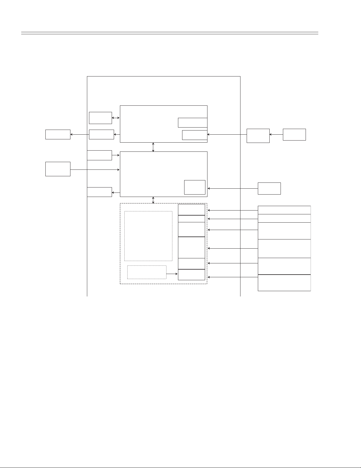
Basic System Block Diagram . . . . . . . . . . . . . . . . . . . . . . . . . . . . . . . . . . . 1-2
Technical Specifications . . . . . . . . . . . . . . . . . . . . . . . . . . . . . . . . . . . . . . . 1-3
Chapter 2 Service & Maintenance . . . . . . . . . . . . . . . . . . . . . . . . . . . . . . . . . . . . 2-1
What You Will Need . . . . . . . . . . . . . . . . . . . . . . . . . . . . . . . . . . . . . . . . . . 2-1
Before You Begin . . . . . . . . . . . . . . . . . . . . . . . . . . . . . . . . . . . . . . . . . . . . . 2-1
Preventive Maintenance . . . . . . . . . . . . . . . . . . . . . . . . . . . . . . . . . . . . . . . 2-1
Visual Inspection . . . . . . . . . . . . . . . . . . . . . . . . . . . . . . . . . . . . . . . . . . . 2-2
Cleaning . . . . . . . . . . . . . . . . . . . . . . . . . . . . . . . . . . . . . . . . . . . . . . . . . . 2-2
Power Cable and Brick Cable . . . . . . . . . . . . . . . . . . . . . . . . . . . . . . . . 2-2
Patient Cable . . . . . . . . . . . . . . . . . . . . . . . . . . . . . . . . . . . . . . . . . . . . . . 2-2
Printhead . . . . . . . . . . . . . . . . . . . . . . . . . . . . . . . . . . . . . . . . . . . . . . . . . 2-3
Service Function Menus and Options . . . . . . . . . . . . . . . . . . . . . . . . . . . . 2-3
Setup Menu . . . . . . . . . . . . . . . . . . . . . . . . . . . . . . . . . . . . . . . . . . . . . . . 2-3
Hidden Menu . . . . . . . . . . . . . . . . . . . . . . . . . . . . . . . . . . . . . . . . . . . . . . 2-4
Special Functions Menu . . . . . . . . . . . . . . . . . . . . . . . . . . . . . . . . . . . . . 2-5
Measuring Chassis Leakage Current . . . . . . . . . . . . . . . . . . . . . . . . . . . . 2-7
Measuring Patient Leakage Current . . . . . . . . . . . . . . . . . . . . . . . . . . . . . 2-8
Chapter 3 Problem Solving . . . . . . . . . . . . . . . . . . . . . . . . . . . . . . . . . . . . . . . . . . . . 3-1
Troubleshooting . . . . . . . . . . . . . . . . . . . . . . . . . . . . . . . . . . . . . . . . . . . . . . 3-1
Connector Pinouts . . . . . . . . . . . . . . . . . . . . . . . . . . . . . . . . . . . . . . . . . . . . 3-4
Power In . . . . . . . . . . . . . . . . . . . . . . . . . . . . . . . . . . . . . . . . . . . . . . . . . . 3-4
Power Supply Board . . . . . . . . . . . . . . . . . . . . . . . . . . . . . . . . . . . . . . . . 3-4
Battery . . . . . . . . . . . . . . . . . . . . . . . . . . . . . . . . . . . . . . . . . . . . . . . . . . . . 3-5
Chapter 4 Component Replacement. . . . . . . . . . . . . . . . . . . . . . . . . . . . . . . . . . 4-1
Battery . . . . . . . . . . . . . . . . . . . . . . . . . . . . . . . . . . . . . . . . . . . . . . . . . . . . . . 4-2
Top Enclosure . . . . . . . . . . . . . . . . . . . . . . . . . . . . . . . . . . . . . . . . . . . . . . . . 4-3
Paper Drive Assembly . . . . . . . . . . . . . . . . . . . . . . . . . . . . . . . . . . . . . . . . 4-4
Queue Sensor . . . . . . . . . . . . . . . . . . . . . . . . . . . . . . . . . . . . . . . . . . . . . . . . 4-5

ii
Atria
Service Manual
Power Supply Board and Power Supply Cover . . . . . . . . . . . . . . . . . . . 4-6
Optional I/O Board and I/O Board Cover . . . . . . . . . . . . . . . . . . . . . . . 4-7
Front End Digital Board . . . . . . . . . . . . . . . . . . . . . . . . . . . . . . . . . . . . . . . 4-8
Parts Lists & Exploded Views . . . . . . . . . . . . . . . . . . . . . . . . . . . . . . . . . . 4-9
Index . . . . . . . . . . . . . . . . . . . . . . . . . . . . . . . . . . . . . . . . . . . . . . . . . . . . . . . In-1

Atria Service Manual
iii
Warnings & Cautions
Warnings
WARNING:
There can be high voltage near the fuse, AC inlet and
transformer. Always unplug the electrocardiograph before taking it
apart.
Cautions
CAUTION:
Always turn the electrocardiograph off and disconnect
the power cord before cleaning. Do not pour liquids (such as alcohol or
other cleaners) on the unit. This will cause severe electrical damage!
CAUTION:
Setting the printhead resistance to any value other than
the value written on the printhead will shorten the life expectancy of
the printhead and may void your warranty.
CAUTION:
Several of the electrocardiograph’s components are
extremely sensitive to static electricity. To minimize the risk of damage,
use a grounding strap and work on an antistatic surface.
CAUTION:
The LCD is very sensitive to static electricity. Use an
antistatic work surface.
CAUTION:
The queue sensor is very sensitive to static electricity. Use
an antistatic work surface.
CAUTION:
The printhead is very sensitive to static electricity. Use an
antistatic work surface.
CAUTION:
The optional I/O board is very sensitive to static
electricity. Use an antistatic work surface.
CAUTION:
The front end digital board is very sensitive to static
electricity. Use an antistatic work surface.
CAUTION:
The power supply board is very sensitive to static
electricity. Use an antistatic work surface.

iv
Atria
Service Manual

Atria Service Manual
v
Definitions of Symbols Used
Attention. Consult accompanying documents.
Danger! High voltage.
Hazardous voltage.
Defibrillation-Protected Type CF Equipment.
Equipotentiality (used to label the grounding lug).
Alternating Current (AC).
Direct Current (DC).
Automatic Operation.
Manual Operation.
On/Standby.
Stop Function.
Modem port.
Ethernet port.
USB port.
Serial port.
Analog port.
Indoor, dry location use only.
No serviceable parts inside.
Meets or exceeds Council Directive 93/42/EEC, MDD, Class IIa.
I0I0

vi
Atria
Service Manual
Certified for both the U.S. and Canadian markets, to the applicable U.S. and
Canadian safety standards.
Component is certified for both the U.S. and Canadian markets, to the
applicable U.S. and Canadian safety standards.
Device or component is certified for the Japanese and/or Asian markets.

Atria Service Manual
1-1
Chapter
1
General Information
About the Atria Electrocardiographs
The Atria ECG is a multichannel non-interpretive/interpretive
electrocardiograph. You operate the electrocardiograph by pressing
various keys on the keypad. A thermal printer makes hard copy
printouts of text and waveforms for permanent records.
The servicing of the Atria electrocardiograph is similar regardless of
which model you have. Some of the information in this Service Manual
applies only to options which you may or may not have installed in
your electrocardiograph. Unless otherwise specified, the information in
this Service Manual applies to the Atria electrocardiographs.
Basic System Description
A simple diagram of the system is shown in Figure . When AC power
is not connected, an internal 14.4 V NiMH battery provides power for
all functions. This battery is recharged whenever the AC line is
connected.
The ECG data is acquired by hybrid circuits and sophisticated software
on the Logic board. Under microprocessor control, the
electrocardiograph samples, buffers and amplifies the analog ECG
signals before converting them to digital levels for further processing.
Input/output control circuitry handles communication with the front
end ECG signals, LCD (liquid crystal display), membrane switches,
thermal printer and external devices (if equipped).

Chapter 1
General Information
1-2
Atria Service Manual
Basic System Block Diagram
Atria 3000
Optional I/O
RS232
IRDA
Analog Out
Dual USB
Host
RJ45
RJ11
I/O Board
Isolation
Supply
(Brick)
AC Power
Software
Upgrades
Software Upgrades
Printers / Database
Management Systems/
Wireless devices
Ethernet
Printers/Database
Management Systems
Analog Phone Lines
Faxes /Database
Management Systems
Printer
1mV =1V out/
Diagnostic equipment
External Modems
Database Management
Systems
Battery
Paper Printer
Power Supply/Printer Board
Power In
Equipotential
LCD
KeyBoard
Patient
Cable Atria Main Board
(Front end and Host processor)
Upgrade
Compact
Flash
Optional Modem

Technical Specifications
Atria Service Manual
1-3
Technical Specifications
Dimensions:
15.0" x 13.125" x 5.5"
(381mm x 334mm x 140mm)
Weight (unit only):
11 lbs (5 kg) (including external power supply)
Display:
Backlit 2 X 40 character LCD
Keyboard:
Full alphanumeric keypad plus designated quick keys
Data Storage:
4 records standard, optional upgrade to 40 or 80
Power Requirements:
AC operation 115/230 V AC ±10%, 50/60 Hz at the external power
source
Battery operation 14.4 V NiMH rechargeable battery pack
Battery duration 30 minutes continuous printing or 30 ECGs
Printout:
Printout device 216 mm thermal dot array
Paper dimension 8.5" x 11" (US letter)
210mm x 300mm (A4)
Paper type Thermal sensitive (Burdick Assurance
®
or
Heartline™ paper recommended)
Chart speeds 10, 25, 50 mm/sec
Gain 5, 10, 20 mm/mV Chest or Limb (may be split)
Printout formats 3, 4, 6 or 12 channels; additional rhythm formats
Acquisition:
Lead selection I, II, III, aVR, aVL, aVF, V1, V2, V3, V4, V5, V6
Supports Frank X,Y, Z; Nehb D,A,J; and Alternate
Chest Lead (chest lead selection V2R through V9R,
V7, V8, and V9)
Modes Automatic, automatic rhythm, or manual rhythm
Frequency response Meets or exceeds ANSI/AAMI EC11-1991 standard
Input impedance Meets or exceeds ANSI/AAMI EC11-1991 standard
Electrode offset tolerance ±300 mV
Effective A/D resolution 5µV LSB
Artifact filter response 40 Hz, -3db
Data resolution 500 samples/second, 5µV
Pacemaker display capability Meets or exceeds ANSI/AAMI EC11-1991 standard
Interpretation (optional) Diagnosis, measurements, reasons statements
based on five demographic criteria

Chapter 1
General Information
1-4
Atria Service Manual
Environmental:
Operating temperature 50°F to 104°F (10°C to 40°C)
Operating relative humidity 10% to 95% non-condensing
Operating atmospheric pressure 1060 hPa to 700 hPa (-500 ft to 10,000 ft reference to
sea level)
Storage temperature -4°F to 131°F (-20°C to 55°C)
Storage relative humidity 25% to 95% non-condensing
Storage atmospheric pressure 1060 hPa to 190 hPa (-500 ft to 40,000 ft reference to
sea level)
Input/Output:
(units with communications) telephone line interface (RJ11)
Ethernet (RJ45)
USB type A
standard RS-232 (9 pin “D”)
analog output (3.5mm phono plug))
IrDA
Conforms to Standards:
CAN/CSA-C22.2 No. 0-M91
CAN/CSA-C22.2 No. 601.1-M90
CAN/CSA-C22.2 No. 601.1S1
CSA C22.2 No. 601.2.25
UL 2601.1
EN 60601-1
EN 60601-2-25 & Amend. 1, excluding 36202.5
EN 60601-1-2, excluding 36.202.6
AZ/NZS 2064.1/2
ANSI/AAMI EC11 - 1991
Safety:
Leakage current patient <10 µA, chassis <100 µA
Defibrillation protection to 5000V, 360J
Equipment Type:
Class IIa (Council Directive 93/42/EEC, MDD)
IEC 601-1 Class I, Type CF
Warranty:
3 years with return of warranty card

Atria Service Manual
2-1
Chapter
2
Service & Maintenance
What You Will Need
You will need only standard electronics tools to perform any testing or repairs.
Test equipment must be in good condition and calibrated regularly. You will
need:
Before You Begin
A few words of caution are in order. Before you perform any service on the
electrocardiograph, be aware of:
High voltage
. There can be high voltage near the fuse, power inlet, and
transformer. Always unplug the electrocardiograph and remove the battery
pack before taking it apart.
Static electricity
. The CMOS (complimentary metal-oxide semiconductor)
chips on the electrocardiograph’s circuit board are extremely sensitive to static
electricity. The printhead and display are also sensitive to static. To minimize
the risk of damage, use a grounding strap and work on an antistatic surface.
Recording paper
. Do not use wax-coated or blush-coated paper in the
electrocardiograph. It will damage the printhead. Use only approved thermal
paper.
Preventive Maintenance
The purpose of preventive maintenance is to reduce or eliminate future
problems. Keeping the electrocardiograph in good operating condition ensures
that it will perform safely and provide accurate recordings.
At least once a year, you should:
✔
Visually inspect the electrocardiograph
✔
Clean the electrocardiograph
✔
Check the power cord
✔
Check the patient cable
✔
Check the leakage currents
If a repair is required, only qualified technicians should do the work.
✔
Digital Multimeter
✔
Leakage Current Meter/Safety Analyzer
✔
Electronic Heart Simulator

Chapter 2
Service & Maintenance
2-2
Atria Service Manual
Visual Inspection
Check for anything out of the ordinary. Are there any cracks or missing parts?
Are the cords and connectors damaged or weak? Does the electrocardiograph
seem to operate properly? If everything looks fine, but you still suspect a
problem, check inside the electrocardiograph for loose connections, burn
damage or contamination from liquids.
Cleaning
CAUTION: Always turn the electrocardiograph off and
disconnect the power cord before cleaning. Do not pour liquids
(such as alcohol or other cleaners) on the unit. This will cause
severe electrical damage!
The need for cleaning depends on the environment and how often the
electrocardiograph is used. Use a damp cloth to clean the housing. Avoid
abrasive cleaners or polishes. Wipe dry with a soft, clean cloth. Don’t forget to
wipe the paper compartment.
Power Cable and Brick Cable
Check the power cord and AC inlet for any visible signs of deterioration, loose
connections or burn damage.
Patient Cable
Check the patient cable and input connector for any visible signs of damage or
loose connections. Disconnect the patient cable from the unit and inspect it for
short circuits, broken wires or poor contacts by measuring the resistance (10k
± 10%) for individual electrode leads.
Brick cable
Power cable
Brick

Service Function Menus and Options
Atria Service Manual
2-3
Printhead
Keep the thermal array printhead free of dirt and other foreign materials.
WARNING: The printhead is very sensitive to static
electricity. Use an antistatic work surface.
Light printing (particularly at the baseline) may be an indication that the
printhead is dirty. Use a small amount of ethanol or isopropyl alcohol and a
lint-free swab to remove residue. Avoid abrasives or cleaners which may
damage the printhead.
Service Function Menus and Options
Setup Menu
Use the
Setup
menu to print system statistics and change the battery saver
mode.
To print system statistics:
NOTE:
This function will print a report of various system
information. This information is divided into the following
categories: Thermal Printer, Power, Front End, Installed
Options, Communications, General, Operating System and
Version Information.
1. Press
.
2. Press
.
3. Press to scroll to
Print System Statistics
.
4. Press
.
To change the battery saver mode:
NOTE:
Modify this option to temporarily disable the auto
power down feature. This will remain in effect until you enable
it again or until you press .
1. Press
.
2. Press
.

Chapter 2
Service & Maintenance
2-4
Atria Service Manual
3. Press
.
4. Press to scroll to
Battery Saver Mode
.
5. Press
.
6. Press to select ON or OFF.
7. Press .
Hidden Menu
The Atria electrocardiographs have a Hidden Menu which you access by
pressing a specific key combination. The service functions in this menu enable
you to perform various tests to verify proper operation. This is also the location
where you set the resistance of the printhead to the correct value.
To access the Hidden Menu:
1. Press .
2. Press .
3. Press and hold down . Simultaneously press
and .
NOTE: If the administrator password has been enabled, then
you must enter the password to continue.
Once you are in the Hidden Menu, scroll through the list of options by
pressing . Press to select a function.
The service functions in the Hidden Menu are listed below.
NOTE: The first three items in the menu are related to product
upgrades and are not part of regular maintenance. These items
are not included below.
Keyboard Test
This function allows you to test the keyboard for proper functioning. Press any
key on the keyboard and verify that the display shows the key selected. This
test is used by Burdick manufacturing.

Service Function Menus and Options
Atria Service Manual 2-5
Factory Defaults
This function allows you to set all of the user programmable defaults back to
their original factory settings. The Atria automatically copies all backup files to
the active directories and powers down and back up again to ensure that the
new defaults are effective.
NOTE: All configuration values are reset to the default
values. Additionally, all passwords are cleared and must be
reset.
Printhead Resistance
Because individual printheads vary in resistance, you must enter the printhead
resistance whenever the logic PCB or paper drive assembly has been replaced.
To enter the printhead resistance:
1. Compare the displayed value to the value written on the
printhead.
2. If the displayed value is incorrect, press backspace three times
to erase the current setting and type in the value printed on the
printhead.
CAUTION: Setting the printhead resistance to any value
other than the value written on the printhead will shorten the
life expectancy of the printhead and may void your warranty.
Printer Test Sequence
This function prints out three test pages which you can use to verify that the
printer is printing correctly across the full width of the printhead.
Printer Test Alternate Sequence
This function prints out a series of test pages which you can use to verify that
the printer is printing correctly across the full width of the printhead. Printer
Test Alternate prints continuously until you press .
Special Functions
This option is used to access the Special Functions menu (see below).
Special Functions Menu
The last option in the Hidden Menu is Special Functions. Use the
Special Functions menu to view, enable or disable features.
NOTE: There may be other functions in addition to those
described below. They are included for Burdick Inc.
Engineering use only.

Chapter 2 Service & Maintenance
2-6 Atria Service Manual
From the Hidden Menu:
1. Press to scroll to Special Functions.
2. Press .
3. Type FET
Continue with step 4 below; or, to enable a feature, continue with step 4 on
page 2-7.
To view or disable features:
4. Enter the following and press :
999999983
5. Press to scroll through the list of features.
NOTE: Some of the features listed are not available currently.
6. Press to select a feature.
NOTE: You may only select features that are currently
enabled.
7. Press to scroll to the OFF option.
8. Press to disable the feature.
NOTE: For storage features, select a different storage capacity,
either 4, 40, or 80 and press .
9. Press .
10. Press .
11.Press .

Measuring Chassis Leakage Current
Atria Service Manual 2-7
Or, to enable features:
4. Enter the password and press .
NOTE: Contact Burdick Technical Support Department for
the password, once the feature has been ordered.
5. Press to select the listed feature.
6. Press to scroll to the ON option.
7. Press to enable the feature.
8. Press .
9. Press .
10. Press .
Measuring Chassis Leakage Current
Use a high quality meter or safety analyzer capable of testing to AAMI
specifications. An inappropriate meter can produce erroneous leakage
readings. Do the leakage tests at a nonconductive work station.
Be careful! The meter must be suitably insulated and capable of withstanding
the power line voltage.
To check the chassis leakage current:
1. Connect a leakage meter between the chassis ground jack (at
rear panel) and power line ground. Make sure the leakage
current is less than 300µA.
2. Open ground line and verify that leakage current is less than
300µA.
3. Reverse line polarity and verify that leakage current is less than
300µA with ground closed.
4. With reversed polarity, open ground line and ensure leakage is
less than 300µA.

Chapter 2 Service & Maintenance
2-8 Atria Service Manual
Measuring Patient Leakage Current
Use a high quality meter or safety analyzer capable of testing to AAMI
specifications. An inappropriate meter can produce erroneous leakage
readings. Do the tests at a nonconductive work station.
Be careful! The meter must be suitably insulated and capable of withstanding
the power line voltage.
To check the patient leakage current:
1. Connect the patient cable to the Atria.
2. Connect all patient cable leads together (it’s easiest to use a
safety analyzer).
3. Connect a leakage meter between patient cable leads and power
line ground. Make sure the leakage is less than 10µA.
4. Open ground line and verify that leakage current is less than
10µA.
5. Reverse line polarity and verify that leakage current is less than
10µA with ground closed.
6. With reversed polarity, open ground line and ensure leakage is
less than 10µA.
Table of contents
Other Burdick Medical Equipment manuals