Burkert 2510 User manual

*Betriebsanleitung Seite 2
*Operating instructions page 3
*Instructions de service page 4
*Manual de instrucciones página 5
Type 2510
Diagnose Diagnosis
Fluid Control Systems
Betriebsanleitung / Operating instructions
Instructions de service / Manual de instrucciones
© 1999 BürkertWerke GmbH & Co.
Alle Rechte vorbehalten.
All rights reserved.
Tous droits réservés.
Reservados todos los derechos.

Typ 2510
Diagnose
Fluid Control Systems
Betriebsanleitung Technische Änderungen vorbehalten
Bürkert Werke GmbH Co. Alle Rechte vorbehalten
Betriebsanleitung-Nr.801 797 01/99/00
BÜRKERT GERMANY
Chr.-Bürkert-Straße 13-17 Berlin Ph: (0 30) 67 97 17 - 0
74653 Ingelfingen Dortmund Ph: (0 23 73) 96 81 - 0
Ph: (0 79 40) 10-0 Dresden Ph: (03 59 52) 36 30 - 0
Fax (0 79 40) 10-204 Frankfurt Ph: (0 61 03) 94 14 - 0
Hannover Ph: (05 11) 9 02 76 - 0
München Ph: (0 89) 82 92 28 - 0
Stuttgart Ph: (07 11) 4 51 10 - 0
BÜRKERT INTERNATIONAL
APh. (01) 8 94 13 33 Fax (01) 8 94 13 00
AUS Ph. (02) 96 74 61 66 Fax (02) 96 74 61 67
BPh. (03) 3 25 89 00 Fax (03) 3 25 61 61
CDN Ph. (9 05) 8 47 55 66 Fax (9 05) 8 47 90 06
CH Ph. (0 41) 7 85 66 66 Fax (0 41) 7 85 66 33
CZ Ph. (06 41) 22 61 80 Fax (06 41) 22 61 81
DK Ph. (0 44) 50 75 00 Fax (0 44) 50 75 75
EPh. (93) 3 71 08 58 Fax (93) 3 71 77 44
ET Ph. (0 40) 54 27 38 Fax (0 40) 54 41 65
FPh. (01) 48 10 31 10 Fax (01) 48 91 90 93
GB Ph. (0 14 53) 73 13 53 Fax (0 14 53) 73 13 43
HKG Ph. 24 80 12 02 Fax 24 18 19 45
IPh. (02) 9 52 01 59 Fax (02) 9 52 90 33
JPh. (03) 32 47 34 11 Fax (03) 32 47 34 72
KOR Ph. (02) 34 62 55 92 Fax (02) 34 62 55 94
NPh. (0 63) 84 44 10 Fax (0 63) 84 44 55
MAL Ph. (04) 6 57 66 49 Fax (04) 6 57 21 06
NL Ph. (0 34) 6 59 53 11 Fax (0 34) 6 56 37 17
NZ Ph. (09) 5 70 25 39 Fax (09) 5 70 25 73
PPh. (01) 4 42 26 08 Fax (01) 4 42 28 08
PL Ph. (0 22) 6 27 47 20 Fax (0 22) 6 27 47 20
RC Ph. (02) 27 58 31 99 Fax (02) 27 58 24 99
SPh. (0 40) 66 45 100 Fax (08) 7 24 60 22
SF Ph. (09) 5 49 70 600 Fax (09) 5 03 12 75
SGP Ph. 3 83 26 12 Fax 3 83 26 11
TR Ph. (02 32) 4 59 53 95 Fax (02 32) 4 59 76 94
USA Ph. (9 49) 2 23 31 00 Fax (9 49) 2 23 31 98
ZA Ph. (0 11) 3 97 29 00 Fax (0 11) 3 97 44 28
LIEBER KUNDE
Herzlichen Glückwunsch zum Kauf dieses Bürkert Gerätes.Lesen
Sie bitte zu Ihrer Sicherheit diese Bedienungsanleitung vor der
Installation des Gerätes genau durch.Fragen beantwortet Ihnen
gerne Ihre zuständige Bürkert-Niederlassung.
Bild 2 : AnschlußbelegungVentilausgang
Ventilausgang
Bild 3 : Typ 2510 Diagnose
Bild 3.1: Einstellung 1 Bild 3.2 : Einstellung 2
Bild 3.3 : Einstellung 3
Potentiometer zur Einstellung der Durchflußschwelle
LED
nicht belegt
Binärausgang
-Ventil
Technischer PE **
+Ventil
- GND
+ 24 V
* für Entstörmaßnahmen/for
Bild 1 : Montage der Gerätesteckdose
Bitte beachten Sie die Hinweise dieser Betriebsanleitung
sowie die Einsatzbedingungen und zulässigen Daten, die in
den Datenblättern der verwendeten Magnetventile sowie der
GerätesteckdoseTyp 2510 Diagnose spezifiziert sind, damit das Gerät
einwandfrei funktioniert und lange einsatzfähig bleibt:
• Halten Sie sich bei Einsatzplanung und Betrieb des Gerätes an die
allgemeinen Regeln derTechnik!
• Eingriffe dürfen nur durch Fachpersonal und mit geeignetem Werk-
zeug erfolgen!
• Treffen Sie geeignete Maßnahmen, um unbeabsichtigtes Betätigen
oder unzulässige Beeinträchtigungen auszuschließen!
• Schalten Sie vor Eingriffen in das System immer die Spannung ab!
• Bei Nichtbeachtung dieser Hinweise sowie unzulässigen Eingriffen in
das Gerät entfällt jegliche Haftung unsererseits, ebenso erlischt die
Garantie auf Geräte u.Zubehörteile!
Die GerätesteckdoseTyp 2510 Diagnose dient zum Erken-
nen von Durchflüssen im MagnetventilTyp 6212.
Medium LED-Anzeige Binärausgang
fließt an "High-Signal" (siehe techn. Daten)
fließt nicht aus "Low-Signal" (siehe techn. Daten)
Tabelle 1:Funktion der GerätesteckdoseTyp 2510 Diagnose
MONTAGE / INBETRIEBNAHME
• Verklemmen Sie die Leitung laut Anschlußplan (Bild 3)
• Schließen Sie die Spannungsversorgung an
• Stecken Sie die Gerätesteckdose auf
EINSTELLUNG (s.Bilder 3, 3.1, 3.2, 3.3)
HINWEIS:Das Magnetventil muß zum Einstellen geschlossen sein
(kein Durchfluß)
1.Drehen Sie das Potentiometer nach links (Bild 3.1) => LED leuchtet
2.Drehen Sie das Potentiometer langsam nach rechts bis LED erlischt
(Bild 3.2)
3.Drehen Sie das Potentiometer um einenTeilstrich weiter nach rechts
(Bild 3.3) HINWEIS: Am Binärausgang muß "Low-Signal" anliegen!
4.Magnetventil öffnen (Durchfluß) => LED muß leuchten!
HINWEIS: Am Binärausgang muß "High-Signal" anliegen!
ACHTUNG! Überprüfen Sie diese Einstellungen in Abhängigkeit
von Schwankungen der Mediumstemperatur regelmäßig alle drei
Monate.Eine Erhöhung der Mediumstemperatur > 24°C/min kann
zu fehlerhaften Meldungen führen!
• Sichern Sie die Gerätesteckdose mit der Zylinderschraube (max.
Anzugsdrehmoment 1 Nm).
ACHTUNG! Achten Sie beimVerschrauben der Gerätesteckdose
mit dem Magnetventil auf den einwandfreien Sitz der Dichtung!
Sicherheitsrelevante Anwendungen
Vor der Anwendung der Gerätesteckdose Typ2510 Diagnose in
sicherheitsrelevanten Anlagen wenden Sie sich bitte an Ihre
zuständige Bürkert-Niederlassung!
DEUTSCH Schalten Sie die GerätesteckdoseTyp 2510 Diagnose vor
Eingriffen spannungsfrei! Ausnahme:Einstellung des Potentio-
meters.
• Ansteuerung des MagnetventilsTyp 6212 direkt über zwei
Eingangsklemmen
• Einstellen der zu erkennenden Durchflußschwelle mit einem
Potentiometer (s.technische Daten)
Betriebsspannung Ue
Schutzkleinspannung1) 24V DC
Restwelligkeit max. 10 %
Eigenverbrauch 1,5W
Betriebstemperatur 0 bis +50 °C
Anschluß Anschlußquerschnitt max. 0,75 mm²
PG16, Leitungsdurchmesser 6-7 mm
Eingang
MagnetventilTyp 6212 24V DC Schutzkleinspannung 1)
Kurzschlußfester Binärausgang / Anzeige LED
Durchfluß ("High")2) max. Ue - 1 V
min. Ue - 3 V
kein Durchfluß ("Low")2) ≤ 1 V
Ausgangsstrom max. 50 mA
LED aus /LED ein2) kein Durchfluß / Durchfluß
Sensor
Ansprechzeit/Abfallzeit ≤ 1 sec / 5 sec
Leistungsaufnahme max. 0,4 Watt
Anwendungsgebiet
Medium / -temperatur Wasser 3) / +10 bis +60 °C
untere Durchflußschwelle 3) DN 10 3 l/min
DN 13 18 l/min
DN 20 30 l/min
obere Durchflußschwelle siehe KV-Wert des Ventils
Gehäuse
Schutzart / Werkstoff IP 65 / PA
Maße 32x32x65 mm
Befestigung Zylinderschraube M2,5x35
Bestell-Nr. 139 827 J
TECHNISCHE DATEN
1) nach VDE 0160
2) bei sachgemäßer Einstellung
3) Informationen über Gerätevarianten mit höheren Auflösungen und für
weitere Medien erhalten Sie in Ihrer zuständigen Bürkert-
Niederlassung

Type 2510
Diagnosis
Fluid Control Systems
Operating instructions We reserve the right to make technical changes without
notice
Bürkert Werke GmbH Co. All rights reserved
Operating Instructions No.801 797 01/99/00
BÜRKERT GERMANY
Chr.-Bürkert-Straße 13-17 Berlin Ph: (0 30) 67 97 17 - 0
74653 Ingelfingen Dortmund Ph: (0 23 73) 96 81 - 0
Ph: (0 79 40) 10-0 Dresden Ph: (03 59 52) 36 30 - 0
Fax (0 79 40) 10-204 Frankfurt Ph: (0 61 03) 94 14 - 0
Hannover Ph: (05 11) 9 02 76 - 0
München Ph: (0 89) 82 92 28 - 0
Stuttgart Ph: (07 11) 4 51 10 - 0
BÜRKERT INTERNATIONAL
APh. (01) 8 94 13 33 Fax (01) 8 94 13 00
AUS Ph. (02) 96 74 61 66 Fax (02) 96 74 61 67
BPh. (03) 3 25 89 00 Fax (03) 3 25 61 61
CDN Ph. (9 05) 8 47 55 66 Fax (9 05) 8 47 90 06
CH Ph. (0 41) 7 85 66 66 Fax (0 41) 7 85 66 33
CZ Ph. (06 41) 22 61 80 Fax (06 41) 22 61 81
DK Ph. (0 44) 50 75 00 Fax (0 44) 50 75 75
EPh. (93) 3 71 08 58 Fax (93) 3 71 77 44
ET Ph. (0 40) 54 27 38 Fax (0 40) 54 41 65
FPh. (01) 48 10 31 10 Fax (01) 48 91 90 93
GB Ph. (0 14 53) 73 13 53 Fax (0 14 53) 73 13 43
HKG Ph. 24 80 12 02 Fax 24 18 19 45
IPh. (02) 9 52 01 59 Fax (02) 9 52 90 33
JPh. (03) 32 47 34 11 Fax (03) 32 47 34 72
KOR Ph. (02) 34 62 55 92 Fax (02) 34 62 55 94
NPh. (0 63) 84 44 10 Fax (0 63) 84 44 55
MAL Ph. (04) 6 57 66 49 Fax (04) 6 57 21 06
NL Ph. (0 34) 6 59 53 11 Fax (0 34) 6 56 37 17
NZ Ph. (09) 5 70 25 39 Fax (09) 5 70 25 73
PPh. (01) 4 42 26 08 Fax (01) 4 42 28 08
PL Ph. (0 22) 6 27 47 20 Fax (0 22) 6 27 47 20
RC Ph. (02) 27 58 31 99 Fax (02) 27 58 24 99
SPh. (0 40) 66 45 100 Fax (08) 7 24 60 22
SF Ph. (09) 5 49 70 600 Fax (09) 5 03 12 75
SGP Ph. 3 83 26 12 Fax 3 83 26 11
TR Ph. (02 32) 4 59 53 95 Fax (02 32) 4 59 76 94
USA Ph. (9 49) 2 23 31 00 Fax (9 49) 2 23 31 98
ZA Ph. (0 11) 3 97 29 00 Fax (0 11) 3 97 44 28
DEAR CUSTOMER
Congratulations on your purchase of this Bürkert unit. For your own
safety, please read carefully through these operating instructions before
installing the unit.Your local Bürkert branch will be pleased to answer
any questions you may have.
Figure 2: Pin allocation of the valve output
Valve outlet
Figure 3:Type 2510 Diagnosis
Figure 3.1: Setting 1 Figure 3.2: Setting 2
Figure 3.3: Setting 3
Potentiometer for adjustment of the flow threshold
LED
not connected
Binary output
-Valve
Technical PE *
+Valve
- GND
+ 24 V
* interference suppression device
Figure 1: Assembly of the device socket
To ensure that the unit functions correctly and will have a long
service life, please comply with the information in these
Operating Instructions, as well as the application conditions
and the permissible data which are specified in the data sheets for the
solenoid valves used, as well as for the Type 2510 Diagnosis device
socket:
• When planning the application of the unit, and during its operation,
observe the general technical rules!
• Work on the unit should only be carried out by specialists using the
correct tools!
• Take adequate measures to prevent unintentional operation or
impermissible impairment!
• Always switch off the supply voltage before carrying out work on the
unit!
• If these instructions are disregarded or if unauthorised work is carried
out on the unit, no liability will be accepted from our side, and the
guarantee on the device and its accessories will become invalid!
TheType 2510 Diagnosis device socket is used for the
detection of flow directions in theType 6212 solenoid valve.
Medium LED display Binary output
Flows on "High-Signal" (seeTechn.Data)
Does not flow off "Low-Signal" (see Techn.Data)
Table 1:Function of the Type 2510 Diagnosis device socket
INSTALLATION / PUTTING INTO SERVICE
• Clamp the lines as shown in the connection diagram (Figure 3)
• Switch on the electrical power supply
• Plug in the device socket
SETTINGS (See Figures 3, 3.1, 3.2, 3.3)
NOTE:The solenoid valvemust be closed while setting up (no flow)
1.Turn the potentiometer to the left (Fig. 3.1) => LED lights up
2.Turn the potentiometer slowly to the right until the LED goes out (Fig.
3.2)
3.Turn the potentiometer further to the right by one graduation (Fig.
3.3).NOTE:There must be a “Low signal”at the binary output!
4.Open the solenoid valve (Flow) => LED must light up!
NOTE:There must be a “High signal” at the binary output!
ATTENTION! Check these settings regularly every three months
depending on the variations of the medium temperature.
An increase of the medium temperature > 24°C/min can lead to
incorrect messages!
• Secure the device socket using the cheese-head screw
(max. tightening torque 1 Nm).
ATTENTION! When screwing the device socket onto the solenoid
valve, ensure that the seal is properly seated!
Applications affecting Safety
Before using theType 2510 Diagnosis device socket in systems which
affect safety, please consult your local Bürkert branch!
ENGLISH Before working on the Type 2510 Diagnosis device socket,
always switch it free of voltage.Exception: Setting the
potentiometer.
• Direct driving of the Type 6212 solenoid valve via two input terminals
• Setting of the flow threshold to be detected using a potentiometer
(see technical data)
TECHNICAL DATA
Operational voltage Ue
Protective low voltage1) 24V DC
Ripple max. 10 %
Own consumption 1,5W
Operational temperature 0 to +50 °C
Connection Fitting cross-section max. 0,75 mm²
PG16, line cross-section 6-7 mm
Input
Type 6212 solenoid valve 24V DC protective low voltage1)
Short-circuit proof binary output / LED display
Flow ("High")2) max. Ue - 1 V
min. Ue - 3 V
No flow ("Low")2) ≤ 1 V
Output current max. 50 mA
LED off / LED on2) No flow / flow
Sensor
Response time / drop-out time ≤ 1 sec / 5 sec
Power consumption max. 0,4 Watt
Area of application
Medium / medium temperature Water 3) / +10 to +60 °C
Lower flow threshold 3) DN 10 3 l/min
DN 13 18 l/min
DN 20 30 l/min
Upper flow threshold see KV value of the valve
Housing
Insulation / Material IP 65 / PA
Dimensions 32x32x65 mm
Fixation M2,5x35 cheesehead screw
Order No. 139 827 J
1) toVDE 0160
2) or correct setting
3) Information about unit variants with higher resolution and for other
media can be obtained from your local Bürkert branch office.

Type 2510
Diagnosis
Fluid Control Systems
Instructions de service Sous resérve de modification techniques.
Bürkert Werke GmbH Co. Tous droits réservés.
Instructions de service no.801 797 01/99/00
BÜRKERT GERMANY
Chr.-Bürkert-Straße 13-17 Berlin Ph: (0 30) 67 97 17 - 0
74653 Ingelfingen Dortmund Ph: (0 23 73) 96 81 - 0
Ph: (0 79 40) 10-0 Dresden Ph: (03 59 52) 36 30 - 0
Fax (0 79 40) 10-204 Frankfurt Ph: (0 61 03) 94 14 - 0
Hannover Ph: (05 11) 9 02 76 - 0
München Ph: (0 89) 82 92 28 - 0
Stuttgart Ph: (07 11) 4 51 10 - 0
BÜRKERT INTERNATIONAL
APh. (01) 8 94 13 33 Fax (01) 8 94 13 00
AUS Ph. (02) 96 74 61 66 Fax (02) 96 74 61 67
BPh. (03) 3 25 89 00 Fax (03) 3 25 61 61
CDN Ph. (9 05) 8 47 55 66 Fax (9 05) 8 47 90 06
CH Ph. (0 41) 7 85 66 66 Fax (0 41) 7 85 66 33
CZ Ph. (06 41) 22 61 80 Fax (06 41) 22 61 81
DK Ph. (0 44) 50 75 00 Fax (0 44) 50 75 75
EPh. (93) 3 71 08 58 Fax (93) 3 71 77 44
ET Ph. (0 40) 54 27 38 Fax (0 40) 54 41 65
FPh. (01) 48 10 31 10 Fax (01) 48 91 90 93
GB Ph. (0 14 53) 73 13 53 Fax (0 14 53) 73 13 43
HKG Ph. 24 80 12 02 Fax 24 18 19 45
IPh. (02) 9 52 01 59 Fax (02) 9 52 90 33
JPh. (03) 32 47 34 11 Fax (03) 32 47 34 72
KOR Ph. (02) 34 62 55 92 Fax (02) 34 62 55 94
NPh. (0 63) 84 44 10 Fax (0 63) 84 44 55
MAL Ph. (04) 6 57 66 49 Fax (04) 6 57 21 06
NL Ph. (0 34) 6 59 53 11 Fax (0 34) 6 56 37 17
NZ Ph. (09) 5 70 25 39 Fax (09) 5 70 25 73
PPh. (01) 4 42 26 08 Fax (01) 4 42 28 08
PL Ph. (0 22) 6 27 47 20 Fax (0 22) 6 27 47 20
RC Ph. (02) 27 58 31 99 Fax (02) 27 58 24 99
SPh. (0 40) 66 45 100 Fax (08) 7 24 60 22
SF Ph. (09) 5 49 70 600 Fax (09) 5 03 12 75
SGP Ph. 3 83 26 12 Fax 3 83 26 11
TR Ph. (02 32) 4 59 53 95 Fax (02 32) 4 59 76 94
USA Ph. (9 49) 2 23 31 00 Fax (9 49) 2 23 31 98
ZA Ph. (0 11) 3 97 29 00 Fax (0 11) 3 97 44 28
CHER CLIENT
Nous vous félicitons cordialement de l’achat de ce produit Bürkert.
Nous vous prions de lire attentivement ces instructions de service
avant l’installation de l’appareil, pour votre propre sécurité.Votre
succursale Bürkert compétente répondra volontiers à toutes vos
questions.
Fig.3:Type
2510 Diagnostic
Figure 3.1: Ajustement 1 Figure 3.2: Ajustement 2
Figure 3.3: Ajustement 3
Potentiomètre de réglage du seuil de débit
LED
Sortie binaire
- vanne
PE technique *
+ vanne
- GND
+ 24 V
* pour déparasitage
Figure1: Montage de la prise d’appareil
Figure2: Raccordement de la prise d’appareil
Sortie de vanne
pas connecté
Nous vous prions d’observer les indications de ces
instructions de service ainsi que les conditions d’utilisation et
les caractéristiques admissibles qui sont spécifiées dans les
fiches techniques de la vanne magnétique utilisée, ainsi que de la prise
d’appareil de type 2510 Diagnostic, afin que l’appareil fonctionne
parfaitement et reste longtemps en état de fonctionnement:
• Respectez lors du projet d’utilisation et de l’exploitation de l’appareil
les règles générales reconnues de la technique!
• Des interventions ne doivent être effectuées que par un personnel
qualifié équipé de l’outillage approprié!
• Prenez les mesures appropriées afin d’exclure une action involontaire
ou des préjudices inadmissibles!
• Déclenchez dans tous les cas la tension électrique avant toute
intervention dans le système!
• En cas d’inobservation de ces indications, ainsi que d’interventions
inadmissibles sur l’appareil, toute responsabilité de notre part sera
exclue, de même que la garantie sur les appareils et les accessoires
sera supprimée!
La prise d’appareil de type 2510 Diagnostic sert à la détection
de débit dans la vanne magnétique type 6212.
Fluide Affichage LED Sortie binaire
s’écoule allumé "High-Signal" (voir caractéristiques techn.)
ne s’écoule éteint "Low-Signal" (voir caractéristiques techn.)
pas
Tableau 1:Fonction de la prise d’appareil de type 2510 Diagnostic
MONTAGE / MISE EN SERVICE
• Raccordez la ligne selon le plan de raccordement (figure 3)
• Raccordez la tension d’alimentation
• Insérez la prise d’apparei
REGLAGE (voir figures 3, 3.1, 3.2, 3.3)
REMARQUE: La vanne magnétique doit être fermée pour le réglage
(pas de débit)
1.Tournez le potentiomètre à gauche (figure 3.1) => la LED s’allume
2.Tournez lentement le potentiomètre à droite (figure 3.2) jusqu’à ce
que la LED s’éteigne
3.Tournez le potentiomètre d’une division plus à droite (figure 3.3).
REMARQUE: Le «signal low» doit être appliqué sur la sortie binaire!
4.Ouvrir la vanne magnétique (débit) => la LED doit être allumée!
REMARQUE: Le «signal high» doit être appliqué sur la sortie
binaire!
ATTENTION!Vérifiez des réglages en fonction des fluctuations de
la température du fluide régulièrement tous les trois mois. Une
élévation de la température du fluide > 24°C/min peut conduire à
des mesures erronées!
• Assurez la prise d’appareil avec la vis à tête cylindrique (couple de
serrage max.1 Nm).
ATTENTION!Veiller en vissant la prise d’appareil avec la vanne
magnétique à une tenue parfaite du joint!
Application déterminantes pour la sécurité
Avant l’application de la prise d’appareil de type 2510 Diagnostic dans
des installations déterminantes pour la sécurité, veuillez vous adresser
à votre succursale Bürkert compétente!
FRANCAIS Déclenchez la prise d’appareil de type 2510 Diagnostic avant
toute intervention! Exception:réglage du potentiomètre.
• Pilotage de la vanne magnétique type 6212 par deux bornes
d’entrée.
• Réglage du seuil de débit avec un potentiomètre
(voir caracteristiques techniques).
CARACTERISTIQUES TECHNIQUES
Tension de service Ue
Tension réduite de protection1) 24 V DC
Ondulation résiduelle max. 10 %
Consommation propre 1,5 W
Température de service 0 à +50 °C
Section de ligne max. 0,75 mm²
PG 16, diamètre de ligne 6-7 mm
Entrée
Vanne magnétique type 6212 24V DC tension réduite de protection 1)
Sortie binaire à l’épreuve des courts-circuits / affichage LED
Débit ("High")2) max. Ue - 1 V
min. Ue - 3 V
Pas de débit ("Low")2) ≤ 1 V
Courant de sortie max. 50 mA
LED éteinte / LED allumée2) pas de débit / débit
Capteur
Temps de réaction / temps de chute ≤ 1 s / 5 s
Puissance consommée max. 0,4 Watt
Domaine d’application
Fluide / température de fluide eau 3) / +10 à +60 °C
Seuil inférieur de débit 3) DN 10 3 l/min
DN 13 18 l/min
DN 20 30 l/min
Seuil supérieur de débit voir valeur Kvde la vanne
Boîtier
Mode de protection / matière IP 65 / PA
Dimensions 32x32x65 mm
Fixation vis à tête cylindrique M2,5x35
N° de commande 139 827 J
1) SelonVDE 0160
2) En cas de réglage conforme
3) Vous obtiendrez des informations sur les variantes d’appareils avec
résulutions supérieures et pour d’autres fluides auprès de votre
représentation Bürkert compétente.

Tipo 2510
Diagnosis
Fluid Control Systems
Manual de instrucciones Nos reservamos el derecho de llevar a cabo modificaciones tècnicas
sin previo aviso.
Bürkert Werke GmbH Co.Reservados todos los derechos.
Manual de instrucciones no801 797 01/99/00
BÜRKERT GERMANY
Chr.-Bürkert-Straße 13-17 Berlin Ph: (0 30) 67 97 17 - 0
74653 Ingelfingen Dortmund Ph: (0 23 73) 96 81 - 0
Ph: (0 79 40) 10-0 Dresden Ph: (03 59 52) 36 30 - 0
Fax (0 79 40) 10-204 Frankfurt Ph: (0 61 03) 94 14 - 0
Hannover Ph: (05 11) 9 02 76 - 0
München Ph: (0 89) 82 92 28 - 0
Stuttgart Ph: (07 11) 4 51 10 - 0
BÜRKERT INTERNATIONAL
APh. (01) 8 94 13 33 Fax (01) 8 94 13 00
AUS Ph. (02) 96 74 61 66 Fax (02) 96 74 61 67
BPh. (03) 3 25 89 00 Fax (03) 3 25 61 61
CDN Ph. (9 05) 8 47 55 66 Fax (9 05) 8 47 90 06
CH Ph. (0 41) 7 85 66 66 Fax (0 41) 7 85 66 33
CZ Ph. (06 41) 22 61 80 Fax (06 41) 22 61 81
DK Ph. (0 44) 50 75 00 Fax (0 44) 50 75 75
EPh. (93) 3 71 08 58 Fax (93) 3 71 77 44
ET Ph. (0 40) 54 27 38 Fax (0 40) 54 41 65
FPh. (01) 48 10 31 10 Fax (01) 48 91 90 93
GB Ph. (0 14 53) 73 13 53 Fax (0 14 53) 73 13 43
HKG Ph. 24 80 12 02 Fax 24 18 19 45
IPh. (02) 9 52 01 59 Fax (02) 9 52 90 33
JPh. (03) 32 47 34 11 Fax (03) 32 47 34 72
KOR Ph. (02) 34 62 55 92 Fax (02) 34 62 55 94
NPh. (0 63) 84 44 10 Fax (0 63) 84 44 55
MAL Ph. (04) 6 57 66 49 Fax (04) 6 57 21 06
NL Ph. (0 34) 6 59 53 11 Fax (0 34) 6 56 37 17
NZ Ph. (09) 5 70 25 39 Fax (09) 5 70 25 73
PPh. (01) 4 42 26 08 Fax (01) 4 42 28 08
PL Ph. (0 22) 6 27 47 20 Fax (0 22) 6 27 47 20
RC Ph. (02) 27 58 31 99 Fax (02) 27 58 24 99
SPh. (0 40) 66 45 100 Fax (08) 7 24 60 22
SF Ph. (09) 5 49 70 600 Fax (09) 5 03 12 75
SGP Ph. 3 83 26 12 Fax 3 83 26 11
TR Ph. (02 32) 4 59 53 95 Fax (02 32) 4 59 76 94
USA Ph. (9 49) 2 23 31 00 Fax (9 49) 2 23 31 98
ZA Ph. (0 11) 3 97 29 00 Fax (0 11) 3 97 44 28
ESTIMADO CLIENTE
Enhorabuena por la compra de este aparato Bürkert! Antes de la
instalación del aparato y por su propia seguridad, lea atentamente
estas Instrucciones de servicio.Su establecimiento competente
Bürkert le aclarará gustosamente toda clase de preguntas al
respecto.
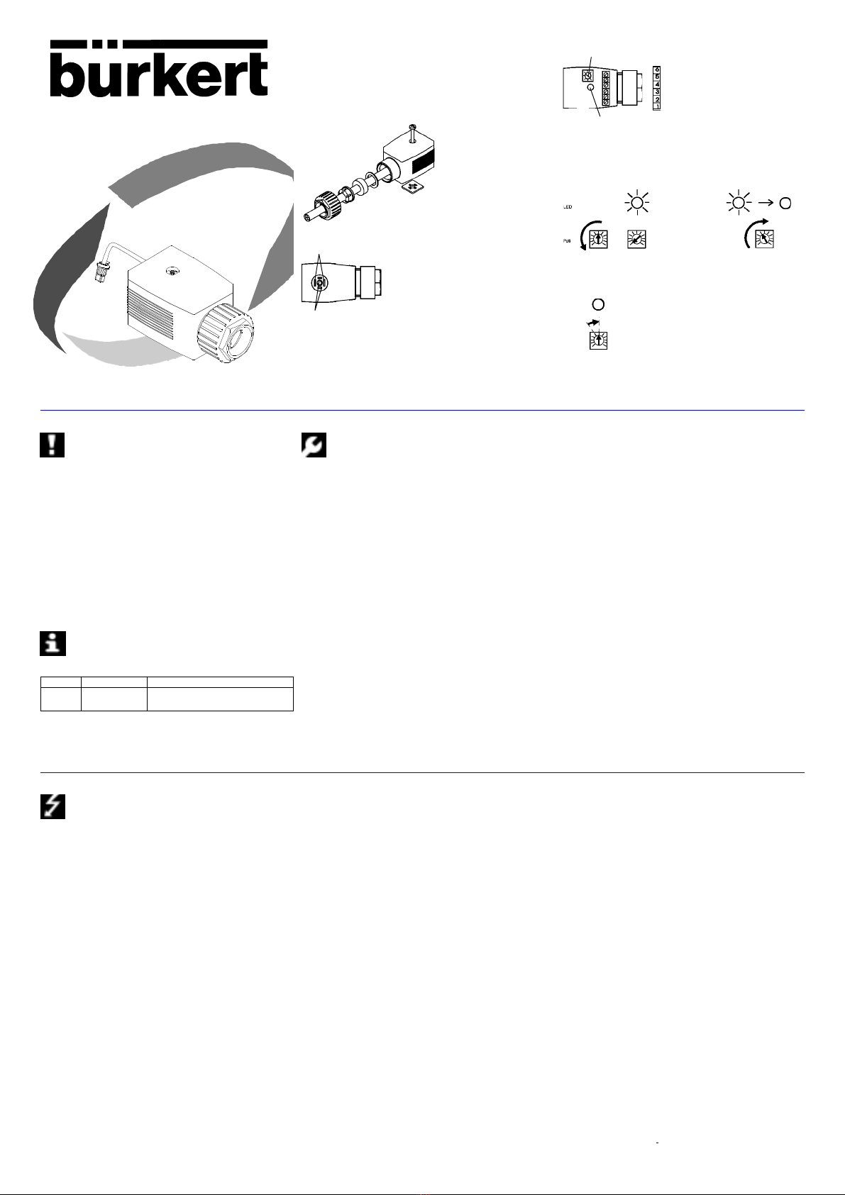
Fig.3:Tipo 2510 Diagnosis
Fig. 3.1: Ajuste 1 Fig. 3.2: Ajuste 2
Fig. 3:3: Ajuste 3
Potenciómetro para el ajuste del umbral de paso
LED
Salida binaria
-Válvula
PE* técnico
+Válvula
- GND
+ 24 V
* para medidas contra parásitos
Fig.1:
Montaje de la caja de enchufe para
aparatos eléctricos
Fig.2: Configuración de bornes de salida de válvula
Salida de válvula
No conectado
Se ruega observar las indicaciones contenidas en estas
Instrucciones de servicio así como las condiciones de uso y
datos admisibles especificados en las hoja de servicio de las
válvulas magnéticas así como de la caja de enchufe para aparatos
eléctricos del tipo 2510 Diagnosis, de modo que el aparato funcione
impecablemente y permanezca durante largo tiempo apto para el
empleo:
• Para la planificación y operación del aparato, atenerse a las reglas
generales de la técnica!
• Las intervenciones solamente deben llevarse a cabo por parte de
personal especialista y con las herramientas adecuadas!
• Tomar las medidas apropiadas para excluir accionamientos no
intencionados o perjuicios inadmisibles!
• Prestar atención a que en sistemas que se encuentran bajo presión
no deben desconectarse conducciones y válvulas!
• La inobservancia de estas indicaciones así como las intervenciones
inadmisibles en el aparato suponen la declinación por nuestra parte
de toda clase de responsabilidad, además de la extinción de la
garantía de los aparatos y de las piezas de accesorios!
La caja de enchufe para aparatos eléctricos del tipo 2510
Diagnosis sirve para reconocer pasos en la válvula magnética
del tipo 2510 y.
Medio Indicación LED Salida binaria
Fluye Llegada "High-Signal" (véanse Datos técnicos)
No fluye No "Low-Signal" (véanse Datos técnicos)
Tabelle 1:Funktion der GerätesteckdoseTyp 2510 Diagnose
MONTAJE / PUESTA EN SERVICIO
• Bloquear la conducción con arreglo al plan de conexión (figura 3)
• Conectar el abastecimiento de tensión
• Enchufar la caja de enchufe para aparatos eléctricos
AJUSTE (véase figuras 3, 3.1, 3.2, 3.3)
INDICACIÓN:La válvula magnética debe estar cerrada para el ajuste
(ningún paso)
1.Girar el potenciómetro hacia la izquierdo (figura 3.1) => luce LED
2.Girar el potenciómetro lentamente hacia la derecha hasta que se
apague el LED (figura 3.2)
3.Girar el potenciómetro una marca de graduación más a la derecha
se (figura 3.3).INDICACIÓN:¡la ”Señal Low”debe situarse en la
salida binaria!
4.Abrir l válvula magnética (paso) => ¡LED debe lucir!
INDICACIÓN:¡la ”Señal High” debe situarse en la salida binaria!
ATENCIÓN: Comprobar estos ajustes independientemente de las
fluctuaciones de la temperatura del medio regularmente >24° C/min
cada tres meses.¡Un aumento de la temperatura del medio puede
conducir a mensajes defectuosos!
• Asegurar la caja de enchufe para aparatos eléctricos con el tornillo
cilíndrico (par máximo de apriete 1 Nm).
ATENCIÓN: ¡Observar que la junta de estanqueidad esté
impecablemente asentada antes de la atornilladura de la caja de
enchufe para aparatos eléctricos!
Aplicaciones relevantes de seguridad
¡Con anterioridad a la aplicación de la caja de enchufe para aparatos
eléctricos del tipo 2510 Diagnosis en instalaciones relevantes de
seguridad dirigirse a su representación competente de Bürkert!
ESPANOL Antes de proceder a intervenciones, conmutar la caja de
enchufe para aparatos eléctricos del tipo 2510 Diagnosis sin
tensión:Ajuste del potenciómetro.
• Mando de la válvula magnética del tipo 6212 directamente a través
de dos bornes de salida.
• Ajuste de los umbrales de paso a reconocer con un potenciómetro
(véase datos tecnicos).
DATOS TÉCNICOS
Tensión de línea Ue
Tensión baja de protección1) 24 V DC
Ondulación residual máx. 10 %
Consumo característico propio 1,5 W
Temperatura de trabajo 0 a +50 °C
Conexión Sección de conexión máx.0,75 mm²
PG16, diámetro de línea 6-7 mm
Entrada
Válvula magnética del tipo 6212 24 V DC tensión baja de protección1)
Salida binaria / Indicación LED resistente al circuito
Paso ("High")2) Máx. Ue - 1 V Mín. Ue - 3 V
Ningún paso ("Low")2) ≤ 1 V
Corriente de salida máx. 50 mA
LED no / LED sí2) Ningún paso / paso
Sensor
Tiempo de reacción /Tiempo
de retardo ≤ 1 seg. / 5 seg.
Consumo de potencia máx. 0,4 Watt
Campo de aplicación
Medio / Temperatura de medio Agua 3) / +10 a +60 °C
Umbral inferior de paso 3) DN 10 3 l/min
DN 13 18 l/min
DN 20 30 l/min
Umbral superior de paso Véase valor Kv de la válvula.
Caja
Modo de protección / Material IP 65 / PA
Dimensiones 32x32x65 mm
Fijación Tornillo cilíndrico M2,5x35
N° de pedido 139 827 J
1) segúnVDE 0160
2) con ajuste conveniente
3) Para más información acerca de variantes de dispositivos con
resoluciones más altas y para otros medios diríjase a su
representación Bürkert más próxima.
Other manuals for 2510
4
Table of contents
Languages: