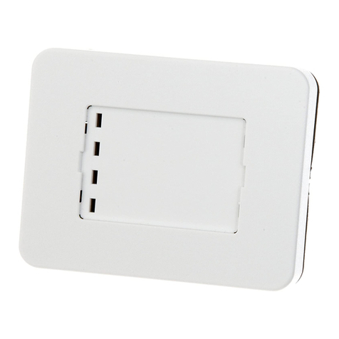
Busch-Jaeger SD/U12.55.11-825 User manual

Product manual │08.09.2023
Busch-Installationsbus®KNX
SD/U12.55.11-825 2.4" Display Balance
SD/U12.63.11-825 2.4" (6.10 cm) Display 63
SD/U12.70.11-4015 2.4" Display Nova
RT/U12.86.11-811 4" RoomTouch®
RT/U12.86.11-825 Busch RoomTouch®4"
Branding -- Releas e 2018-01-01

Table of contents
Product manual 2CKA001473B5472
│
2
Table of contents
1
Notes on the instruction manual..................................................................................................................12
2
Safety...........................................................................................................................................................13
2.1
Information and symbols used.........................................................................................................13
2.2
Intended use ....................................................................................................................................14
2.3
Improper use ....................................................................................................................................14
2.4
Target group / Qualifications of personnel.......................................................................................15
2.4.1
Operation ................................................................................................................................... 15
2.4.2
Installation, commissioning and maintenance ............................................................................ 15
2.5
Cyber security ..................................................................................................................................16
2.6
Safety instructions............................................................................................................................18
3
Information on protection of the environment .............................................................................................19
3.1
Environment .....................................................................................................................................19
4
Product Overview ........................................................................................................................................20
4.1
Scope of supply................................................................................................................................21
4.2
Accessories ......................................................................................................................................21
4.3
Overview of types.............................................................................................................................21
4.4
Overview of KNX functions ..............................................................................................................22
4.5
Device overview ...............................................................................................................................23
5
Technical data .............................................................................................................................................25
5.1
Dimensional drawings......................................................................................................................27
5.2
Circuit diagrams ...............................................................................................................................28
6
Connection, installation / mounting .............................................................................................................29
6.1
Planning instructions........................................................................................................................29
6.2
Safety instructions............................................................................................................................29
6.3
Requirements for the electrician ......................................................................................................29
6.4
Electrical connection ........................................................................................................................30
6.4.1
Connection................................................................................................................................. 30
6.5
Mounting / dismantling .....................................................................................................................31
6.5.1
Installation sites.......................................................................................................................... 31
6.5.2
Removal protection .................................................................................................................... 32
6.5.3
Mounting .................................................................................................................................... 33
6.6
Dismantling.......................................................................................................................................35
7
Commissioning of the KNX function via DCA .............................................................................................36
7.1
Integration into the KNX system (ETS)............................................................................................36
7.1.1
Prerequisites .............................................................................................................................. 36
7.1.2
Installation of the ETS app ......................................................................................................... 37
7.1.3
Installation sequence.................................................................................................................. 38
7.1.4
Integrating the display into the ETS........................................................................................... 38
7.2
Overview of the DCA commissioning tool .......................................................................................39
7.2.1
Starting the DCA ........................................................................................................................ 39
7.3
Screen areas of the DCA .................................................................................................................40

Table of contents
Product manual 2CKA001473B5472
│
3
7.4
Explanation of the basic structure (Terms)......................................................................................42
7.5
Commissioning sequence................................................................................................................43
7.6
Configuration of system settings of the display ...............................................................................43
7.6.1
Basic settings (system settings) of the panel.............................................................................. 44
7.7
Creating the navigation structure.....................................................................................................56
7.7.1
Creating operating pages........................................................................................................... 56
7.7.2
Editing operating pages.............................................................................................................. 57
7.8
Configuration of the operating pages...............................................................................................59
7.8.1
"Switch" control element............................................................................................................. 60
7.8.2
Control element "Rocker switch" ................................................................................................ 60
7.8.3
"Dimmer" control element........................................................................................................... 60
7.8.4
Control element: "Dimmer slider" ............................................................................................... 60
7.8.5
Operation of "RGBW" control element“ ...................................................................................... 60
7.8.6
Control element: "Value slider"................................................................................................... 61
7.8.7
"Blind" control element ............................................................................................................... 61
7.8.8
Control element "Fan switch" ..................................................................................................... 61
7.8.9
"Scene" control element ............................................................................................................. 61
7.8.10
Control element "RTC control element"...................................................................................... 61
7.8.11
Control element "Split Unit Control"............................................................................................ 62
7.8.12
Control element "VRV control" ................................................................................................... 62
7.8.13
Control element "Audio control".................................................................................................. 62
7.9
Editing control elements...................................................................................................................63
7.9.1
Delete control element ............................................................................................................... 63
7.9.2
Copy control element ................................................................................................................. 64
7.9.3
Add control element to favourites list.......................................................................................... 64
7.10
Configuration of applications and application pages .......................................................................65
7.10.1
Application "Information page" ................................................................................................... 65
7.10.2
Application "Input" ...................................................................................................................... 65
7.10.3
Application "Scene actuator" ...................................................................................................... 66
7.10.4
Application "Logical functions".................................................................................................... 67
7.10.5
Application "Internal RTC".......................................................................................................... 67
7.10.6
"Favourite control elements"....................................................................................................... 68
7.11
Editing communication objects ........................................................................................................69
7.12
Editing group addresses ..................................................................................................................70
7.13
Additional tools (functions)...............................................................................................................71
7.13.1
Import......................................................................................................................................... 71
7.13.2
Export......................................................................................................................................... 72
7.13.3
Preview ...................................................................................................................................... 72
7.13.4
Reset layout ............................................................................................................................... 72
7.13.5
Reset all ..................................................................................................................................... 73
7.13.6
Repair ........................................................................................................................................ 73
7.13.7
Visible / Not visible ..................................................................................................................... 73
8
Control elements and application parameter ..............................................................................................74
8.1
"Switch" control element ..................................................................................................................74
8.1.1
Name of the control element ...................................................................................................... 74
8.1.2
Activating optional designation for control elements................................................................... 74
8.1.3
Optional designation of the control element ............................................................................... 74
8.1.4
Type of switch ............................................................................................................................ 74

Table of contents
Product manual 2CKA001473B5472
│
4
8.1.5
Object type value 1/2.................................................................................................................. 75
8.1.6
Type of icon................................................................................................................................ 78
8.1.7
Status control element (icon/text) is operated via a separate object........................................... 79
8.1.8
Icon for On ................................................................................................................................. 79
8.1.9
Icon for Off ................................................................................................................................. 79
8.1.10
Enable 1-bit communication object "Disable" ............................................................................. 79
8.2
Control element "Rocker switch" .....................................................................................................80
8.2.1
Name of the control element ...................................................................................................... 80
8.2.2
Optional label of control element is active .................................................................................. 80
8.2.3
Icon type..................................................................................................................................... 81
8.2.4
Status control element (icon/text) is operated via a separate object........................................... 81
8.2.5
Object type................................................................................................................................. 82
8.2.6
Enable 1-bit communication object "Disable" ............................................................................. 85
8.3
"Dimmer" control element ................................................................................................................86
8.3.1
Name of the control element ...................................................................................................... 86
8.3.2
Activating optional designation for control elements................................................................... 86
8.3.3
Optional designation of the control element ............................................................................... 86
8.3.4
Additional value of status object ................................................................................................. 86
8.3.5
Additional switch status object.................................................................................................... 87
8.3.6
Manner of dimming..................................................................................................................... 87
8.3.7
Enable 1-bit communication object "Disable" ............................................................................. 88
8.4
Control element: "Dimmer slider".....................................................................................................89
8.4.1
Name of the control element ...................................................................................................... 89
8.4.2
Activating optional designation for control elements................................................................... 89
8.4.3
Optional designation of the control element ............................................................................... 89
8.4.4
Additional value of status object ................................................................................................. 89
8.4.5
Additional switch status object.................................................................................................... 90
8.4.6
Slider sends ............................................................................................................................... 90
8.4.7
Brightness change [%] ............................................................................................................... 90
8.4.8
Enable 1-bit communication object "Disable" ............................................................................. 90
8.5
Operation of "RGBW" control element“ ...........................................................................................91
8.5.1
Name of the control element ...................................................................................................... 91
8.5.2
Activating optional designation for control elements................................................................... 91
8.5.3
Optional designation of the control element ............................................................................... 91
8.5.4
Additional switch status object.................................................................................................... 91
8.5.5
Type of colour/white lamp .......................................................................................................... 92
8.5.6
Brightness change [%] ............................................................................................................... 95
8.5.7
Telegram is repeated every [sec.]: ............................................................................................. 95
8.5.8
Switched On -> preset value: ..................................................................................................... 96
8.5.9
Switched Off -> RGB value 0,0,0:............................................................................................... 96
8.5.10
Enable 1-bit communication object "Disable" ............................................................................. 96
8.6
Control element: "Value slider" ........................................................................................................97
8.6.1
Name of the control element ...................................................................................................... 97
8.6.2
Activating optional designation for control elements................................................................... 97
8.6.3
Optional designation of the control element ............................................................................... 97
8.6.4
Display value in control element................................................................................................. 97
8.6.5
Status value is controlled by a separate object .......................................................................... 98
8.6.6
Unit............................................................................................................................................. 98
8.6.7
Decimals .................................................................................................................................... 98
8.6.8
Slider sends ............................................................................................................................... 98
8.6.9
Value change ............................................................................................................................. 99

Table of contents
Product manual 2CKA001473B5472
│
5
8.6.10
Object type................................................................................................................................. 99
8.6.11
Minimum object value................................................................................................................101
8.6.12
Maximum object value...............................................................................................................101
8.6.13
Displayed minimum value .........................................................................................................101
8.6.14
Displayed maximum value ........................................................................................................101
8.6.15
Enable 1-bit communication object "Disable" ............................................................................102
8.7
"Blind" control element...................................................................................................................103
8.7.1
Name of the control element .....................................................................................................103
8.7.2
Activating optional designation for control elements..................................................................103
8.7.3
Optional designation of the control element ..............................................................................103
8.7.4
Using 1-byte positioning ............................................................................................................103
8.7.1
Icon type....................................................................................................................................104
8.7.2
Time limit for displaying stop icon after movement [s] ...............................................................104
8.7.3
Type of control ..........................................................................................................................104
8.7.4
Status control element (icon/text) is operated via a separate object..........................................105
8.7.5
Enable 1-bit communication object "Disable" ............................................................................106
8.8
Control element "Fan switch".........................................................................................................107
8.8.1
Name of the control element .....................................................................................................107
8.8.2
Activating optional designation for control elements..................................................................107
8.8.3
Optional designation of the control element ..............................................................................107
8.8.4
Deactivation of switch-off option................................................................................................107
8.8.5
Number of levels .......................................................................................................................107
8.8.6
Object type................................................................................................................................107
8.8.7
Status control element (icon/text) is operated via a separate object..........................................110
8.8.8
Enable 1-bit communication object "Disable" ............................................................................110
8.9
"Scene" control element.................................................................................................................111
8.9.1
Name of the control element .....................................................................................................111
8.9.2
Activating optional designation for control elements..................................................................111
8.9.3
Optional designation of the control element ..............................................................................111
8.9.4
Function icon.............................................................................................................................111
8.9.5
Status of control is controlled by a separate object ...................................................................112
8.9.6
Number of the scene x [1-64] ....................................................................................................112
8.9.7
Store scene with long press of button........................................................................................112
8.9.8
Long operation after... ...............................................................................................................112
8.9.9
Enable 1-bit communication object "Disable" ............................................................................112
8.10
Control element "RTC control element".........................................................................................113
8.10.1
Name of the control element .....................................................................................................113
8.10.2
Activating optional designation for control elements..................................................................113
8.10.3
Optional designation of the control element ..............................................................................113
8.10.4
Additional functions/objects.......................................................................................................113
8.10.5
Delay time for read telegrams after reset [sec.].........................................................................113
8.10.6
Main displayed temperature is...................................................................................................114
8.10.7
Display optional temperature.....................................................................................................114
8.10.8
Main RTC operates ...................................................................................................................114
8.10.9
Hide temperature unit................................................................................................................115
8.10.10
Fan coil control during heating mode ........................................................................................115
8.10.11
Fan coil control during cooling mode.........................................................................................115
8.10.12
Use condensate alarm (via extra 1-bit comm. object)................................................................115
8.10.13
Comfort mode setting ................................................................................................................116
8.10.14
Setting of Standby mode ...........................................................................................................116
8.10.15
Setting of Economy mode .........................................................................................................116

Table of contents
Product manual 2CKA001473B5472
│
6
8.10.16
Setting of Building Protection mode ..........................................................................................116
8.10.17
Step size of setpoint adjustment................................................................................................117
8.10.18
Setpoint adjustment main/secondary via communication object................................................117
8.10.19
Upper limit for setpoint adjustment ............................................................................................118
8.10.20
Lower limit for setpoint adjustment ............................................................................................118
8.10.21
Enable 1-bit communication object "Disable" ............................................................................118
8.11
Control "Split Unit Control".............................................................................................................119
8.11.1
Name of the control element .....................................................................................................119
8.11.2
Activating optional designation for control elements..................................................................119
8.11.3
Optional designation of the control element ..............................................................................119
8.11.4
Displayed main temperature is..................................................................................................119
8.11.5
Display optional designation......................................................................................................120
8.11.6
Minimum setpoint ......................................................................................................................121
8.11.7
Maximum setpoint .....................................................................................................................121
8.11.8
Step size of setpoint adjustment................................................................................................121
8.11.9
Number of fan speed levels (without AUTO) .............................................................................122
8.11.10
Use automatic mode for fans.....................................................................................................122
8.11.11
Use mode: Automatic ................................................................................................................122
8.11.12
Use mode: Heating....................................................................................................................122
8.11.13
Use mode: Cooling....................................................................................................................123
8.11.14
Use mode: Drying......................................................................................................................123
8.11.15
Use mode: Fan..........................................................................................................................123
8.11.16
Use horizontal oscillation...........................................................................................................123
8.11.17
Use vertical oscillation...............................................................................................................123
8.11.18
Use extra mode: Silence Mode .................................................................................................124
8.11.19
Use additional mode: Boost ......................................................................................................124
8.11.20
Use additional mode: Forced operation.....................................................................................124
8.11.21
Use additional mode: Scene......................................................................................................124
8.11.22
Additional mode Use window contact........................................................................................125
8.11.23
Use additional Presence mode..................................................................................................125
8.11.24
Enable 1-bit communication object "Disable" ............................................................................125
8.12
"VRV control element"....................................................................................................................126
8.12.1
Name of the control element .....................................................................................................126
8.12.2
Activating optional designation for control elements..................................................................126
8.12.3
Optional designation of the control element ..............................................................................126
8.12.4
Displayed main temperature is..................................................................................................126
8.12.5
Value [1 byte 0-255] for heating mode.......................................................................................127
8.12.6
Value [1 byte 0-255] for cooling mode.......................................................................................127
8.12.7
Using only fan operation............................................................................................................127
8.12.8
Value [1 byte 0-255] for "Only fan operation" ............................................................................127
8.12.9
Using dehumidification operation ..............................................................................................127
8.12.10
Value [1 byte 0-255] for dehumidification operation...................................................................127
8.12.11
Using automatic operation.........................................................................................................128
8.12.12
Value [1 byte 0-255] for automatic operation.............................................................................128
8.12.13
Fan speed levels .......................................................................................................................129
8.12.14
Value for the speed x ................................................................................................................129
8.12.15
Using automatic fan speed control ............................................................................................129
8.12.16
Value for automatic fan speed x................................................................................................129
8.12.17
Step size ...................................................................................................................................130
8.12.18
Maximum setpoint [°C] ..............................................................................................................130
8.12.19
Minimum setpoint [°C] ...............................................................................................................130

Table of contents
Product manual 2CKA001473B5472
│
7
8.12.20
Using VRV temperature sensor error display ............................................................................131
8.12.21
Using VRV error display ............................................................................................................131
8.12.22
Value for cancelling the VRV error display ................................................................................131
8.12.23
Enable 1-bit communication object "Disable" ............................................................................131
8.13
Control element "Audio control".....................................................................................................132
8.13.1
Title of control element ..............................................................................................................132
8.13.2
Name of the control element .....................................................................................................132
8.13.3
Subtitle of the control element...................................................................................................132
8.13.4
Activating optional designation for control elements..................................................................132
8.13.5
Optional designation of the control element ..............................................................................132
8.13.6
Number of sources....................................................................................................................133
8.13.7
Object type Playback / Pause control........................................................................................133
8.13.8
Use forward/reverse control ......................................................................................................134
8.13.9
Object type Forward/reverse control..........................................................................................134
8.13.10
Use of button for mute...............................................................................................................135
8.13.1
Use shuffle control.....................................................................................................................136
8.13.2
Use repeat control.....................................................................................................................137
8.13.3
Use of volume button ................................................................................................................138
8.13.4
Use of ON/OFF button ..............................................................................................................139
8.13.5
Enable 1-bit communication object "Disable" ............................................................................140
8.14
Application "Inputs" ........................................................................................................................141
8.14.1
Use binary input ........................................................................................................................141
8.15
Application "Internal RTC" .............................................................................................................149
8.15.1
Number of notifications..............................................................................................................149
8.15.2
Notification x active ...................................................................................................................149
8.15.3
Title ...........................................................................................................................................149
8.15.4
Icon ...........................................................................................................................................149
8.15.5
Unit............................................................................................................................................150
8.15.6
Minimum object value................................................................................................................150
8.15.7
Maximum object value...............................................................................................................150
8.15.8
Displayed minimum value .........................................................................................................150
8.15.9
Displayed maximum value ........................................................................................................150
8.15.10
Number of coloured status indication levels ..............................................................................150
8.15.11
Activating red text highlighting for alarms..................................................................................151
8.15.12
Activating popup notification window.........................................................................................151
8.15.13
Type of the notification window .................................................................................................151
8.15.14
Closing the notification window automatically............................................................................152
8.15.15
Value for activating the notification window ...............................................................................152
8.15.16
Activating notification window at current value ..........................................................................152
8.15.17
Value at which the notification window is deactivated automatically..........................................152
8.15.18
Deactivating notification window at current value ......................................................................153
8.15.19
Notification text..........................................................................................................................153
8.16
Application "Scene actuator"..........................................................................................................154
8.16.1
Name of scene actuator ............................................................................................................154
8.16.2
Number of participants ..............................................................................................................154
8.16.3
Number of scenes .....................................................................................................................154
8.16.4
Overwriting scenes during download.........................................................................................154
8.16.5
Telegram delay .........................................................................................................................154
8.16.6
Object type x .............................................................................................................................155
8.16.7
Name of scene ..........................................................................................................................158
8.16.8
Scene number...........................................................................................................................158

Table of contents
Product manual 2CKA001473B5472
│
8
8.16.9
Scene can be started with a ......................................................................................................158
8.16.10
Scene can be saved..................................................................................................................158
8.16.11
Value for object x ......................................................................................................................158
8.17
Application "Logical functions" .......................................................................................................159
8.17.1
Channel x — Application ...........................................................................................................159
8.18
Application "Internal RTC" .............................................................................................................173
8.18.1
General - Control function .........................................................................................................173
8.18.2
General - Operating mode after reset........................................................................................173
8.18.3
General - Additional functions/objects .......................................................................................174
8.18.4
General — Delay time for read telegrams after reset [s]............................................................174
8.18.1
General - "Current HVAC operating mode" object active...........................................................174
8.18.2
Heating control ..........................................................................................................................175
8.18.3
Heating control - Control value type ..........................................................................................175
8.18.4
Heating control — Heating type.................................................................................................176
8.18.5
Heating control — P-component ...............................................................................................176
8.18.6
Heating control — I-component.................................................................................................176
8.18.7
Heating control — Extended settings ........................................................................................177
8.18.8
Basic stage heating...................................................................................................................178
8.18.9
Basic stage heating — Status object heating ............................................................................178
8.18.10
Basic stage heating — Mode of the control value......................................................................178
8.18.11
Basic stage heating — Hysteresis.............................................................................................178
8.18.12
Basic stage heating — Control value difference for sending of heating control value................178
8.18.13
Basic stage heating — Cyclic sending of the control value........................................................179
8.18.14
Additional stage heating - PWM cycle heating ..........................................................................179
8.18.15
Basic stage heating — Maximum control value (0 - 255)...........................................................179
8.18.16
Basic stage heating — Minimum control value for basic load (0 to 255)....................................179
8.18.17
Control of additional heating stage ............................................................................................180
8.18.18
Control of additional heating stage — Control value type..........................................................180
8.18.19
Control of additional heating stage — Additional heating type...................................................180
8.18.20
Control of additional heating stage - P-component....................................................................181
8.18.21
Control of additional heating stage - I-component .....................................................................181
8.18.22
Control of additional heating stage - Temperature difference to basic stage .............................181
8.18.23
Control of additional heating stage - Extended settings.............................................................182
8.18.24
Additional heating stage ............................................................................................................183
8.18.25
Additional heating stage — Mode of the control value...............................................................183
8.18.26
Additional stage heating - PWM cycle heating ..........................................................................183
8.18.27
Additional heating stage — Control value difference for sending of heating control value.........183
8.18.28
Additional heating stage - Cyclic sending of the control value ...................................................184
8.18.29
Additional heating stage — Maximum control value (0 - 255)....................................................184
8.18.30
Additional heating stage — Minimum control value for basic load (0 - 255) ..............................184
8.18.31
Additional heating stage - Hysteresis ........................................................................................185
8.18.32
Cooling control ..........................................................................................................................186
8.18.33
Cooling control — Control value type ........................................................................................186
8.18.34
Cooling control — Cooling type .................................................................................................187
8.18.35
Cooling control - P-component ..................................................................................................187
8.18.36
Cooling control - I-component ...................................................................................................187
8.18.37
Cooling control - Extended settings...........................................................................................188
8.18.38
Basic stage cooling ...................................................................................................................188
8.18.39
Basic stage cooling — Status object cooling .............................................................................188
8.18.40
Basic stage cooling — Mode of the control value......................................................................188
8.18.41
Basic stage heating - Control value difference for sending of heating control value ..................188

Table of contents
Product manual 2CKA001473B5472
│
9
8.18.42
Basic stage cooling — Cyclic sending of the control value........................................................189
8.18.43
Basic stage cooling — Hysteresis .............................................................................................189
8.18.44
Basic stage cooling — PWM cycle cooling (min).......................................................................189
8.18.45
Basic stage cooling — Maximum control value (0 - 255)...........................................................190
8.18.46
Basic stage cooling — Minimum control value for basic load (0 to 255) ....................................190
8.18.47
Control of additional cooling stage ............................................................................................191
8.18.48
Control of additional cooling stage - Control value type.............................................................191
8.18.49
Control of additional cooling stage — Cooling type ...................................................................191
8.18.50
Control of additional cooling stage — P-component..................................................................192
8.18.51
Control of additional cooling stage — I-component ...................................................................192
8.18.52
Control of additional cooling stage - Temperature difference to basic stage..............................192
8.18.53
Control of additional cooling stage — Extended settings...........................................................193
8.18.54
Additional cooling stage ............................................................................................................193
8.18.55
Additional cooling stage — Mode of the control value ...............................................................193
8.18.56
Additional stage cooling — PWM cycle cooling (min)................................................................193
8.18.57
Additional cooling stage — Control value difference for sending of cooling control value..........194
8.18.58
Additional cooling stage — Cyclic sending of the control value .................................................194
8.18.59
Additional cooling stage — Maximum control value (0 - 255) ....................................................194
8.18.60
Additional cooling stage — Minimum control value for basic load (0 - 255)...............................195
8.18.61
Additional cooling stage — Hysteresis ......................................................................................195
8.18.62
Settings of basic load ................................................................................................................196
8.18.63
Settings of basic load — Minimum control value for basic load > 0...........................................196
8.18.64
Basic load settings — Basic load active when controller is off...................................................196
8.18.65
Combined heating and cooling modes ......................................................................................197
8.18.66
Combined heating and cooling modes — Switchover of heating/cooling...................................197
8.18.67
Combined heating and cooling modes — Operating mode after reset ......................................197
8.18.68
Combined heating and cooling modes — Heating/cooling control value output ........................197
8.18.69
Combined heating and cooling modes — Additional heating/cooling stage control value
output ........................................................................................................................................198
8.18.70
Setpoint settings........................................................................................................................199
8.18.71
Setpoint settings — Setpoint for heating comfort = setpoint for cooling comfort........................199
8.18.72
Setpoint settings - Setpoint for standby and Eco are absolute values .......................................199
8.18.73
Setpoint settings - Hysteresis for switchover heating/cooling ....................................................199
8.18.74
Setpoint settings — Setpoint for heating and cooling comfort ...................................................200
8.18.75
Setpoint settings — Setpoint for heating comfort.......................................................................200
8.18.76
Setpoint settings — Setpoint for heating standby......................................................................200
8.18.77
Setpoint settings — Reduction for standby heating by ..............................................................200
8.18.78
Setpoint settings — Setpoint for heating economy ....................................................................200
8.18.79
Setpoint settings — Reduction for heating economy by ............................................................201
8.18.80
Setpoint settings — Setpoint for heating building protection......................................................201
8.18.81
Setpoint settings — Setpoint for cooling comfort.......................................................................202
8.18.82
Setpoint settings — Setpoint for cooling standby ......................................................................202
8.18.83
Setpoint settings — Increase for cooling standby by .................................................................202
8.18.84
Setpoint settings — Setpoint for cooling economy ....................................................................202
8.18.85
Setpoint settings — Increase for cooling economy....................................................................202
8.18.86
Setpoint settings — Setpoint for cooling building protection......................................................203
8.18.87
Setpoint settings — Setpoint setting via communication object (DPT 9.001).............................203
8.18.88
Setpoint settings — Display.......................................................................................................203
8.18.89
Setpoint settings - Hide temperature unit ..................................................................................203
8.18.90
Setpoint settings — Send current setpoint ................................................................................204
8.18.91
Setpoint settings - Cyclic sending of the current setpoint ..........................................................204
8.18.92
Setpoint settings - Basic set value is .........................................................................................204

Table of contents
Product manual 2CKA001473B5472
│
10
8.18.93
Setpoint adjustment...................................................................................................................204
8.18.94
Setpoint adjustment — Maximum manual increase during heating mode (0 - 9°C)...................204
8.18.95
Setpoint adjustment — Maximum manual reduction during heating mode (0 - 9°C)..................205
8.18.96
Setpoint adjustment — Maximum manual increase during cooling mode (0 - 9°C) ...................205
8.18.97
Setpoint adjustment — Maximum manual reduction during cooling mode (0 - 9°C) ..................205
8.18.98
Setpoint adjustment - Step size of manual setpoint adjustment ................................................205
8.18.99
Setpoint adjustment - Setpoint adjustment master/slave via communication object ..................206
8.18.100
Setpoint adjustment — Resetting of the manual adjustment for receipt of a basic setpoint.......206
8.18.101
Setpoint adjustment — Resetting the manual adjustment for change of operating mode..........207
8.18.102
Setpoint adjustment — Resetting the manual adjustment via object .........................................207
8.18.103
Setpoint adjustment — Permanent storage of on-site operation ...............................................207
8.18.104
Temperature reading.................................................................................................................208
8.18.105
Temperature reading — Inputs of temperature reading.............................................................208
8.18.106
Temperature reading — Inputs of weighted temperature reading .............................................208
8.18.107
Temperature reading — Weighting of internal measurement (0 to 100%).................................208
8.18.108
Temperature reading — Weighting of external measurement (0 to 100%)................................208
8.18.109
Temperature reading — Weighting of external measurement 2 (0 to 100%).............................209
8.18.110
Temperature reading — Cyclic sending of the actual temperature (min)...................................209
8.18.111
Temperature reading — Difference of value for sending the actual temperature.......................209
8.18.112
Temperature reading — Adjustment value for internal temperature measurement ...................209
8.18.113
Temperature reading — Adjustment value for internal temperature measurement via object....210
8.18.114
Temperature reading — Monitoring of temperature reading......................................................210
8.18.115
Temperature reading — Monitoring time for temperature reading.............................................210
8.18.116
Temperature reading — Operating mode for fault .....................................................................211
8.18.117
Temperature reading — Control value for fault (0 - 255) ...........................................................211
8.18.118
Alarm functions .........................................................................................................................212
8.18.119
Alarm functions - Condensate water alarm................................................................................212
8.18.120
Alarm functions — Dew point alarm ..........................................................................................212
8.18.121
Alarm functions - Frost alarm temperature for HVAC and RHCC status (°C) ............................212
8.18.122
Alarm functions - Heat alarm temperature for RHCC status (°C)...............................................213
8.18.123
Temperature limiter ...................................................................................................................214
8.18.124
Temperature limiter - Temperature limit of heating....................................................................214
8.18.125
Temperature limiter - Temperature limit of additional heating stage..........................................214
8.18.126
Temperature limiter - Setpoint temperature of heating / additional heating stage......................214
8.18.127
Temperature limiter - Temperature limit of cooling ....................................................................214
8.18.128
Temperature limiter - Temperature limit additional cooling stage ..............................................214
8.18.129
Temperature limiter - Setpoint temperature of cooling / additional cooling stage.......................215
8.18.130
Temperature limiter - Hysteresis ...............................................................................................215
8.18.131
Temperature limiter - Integral component of PI controller..........................................................215
8.18.132
Summer compensation .............................................................................................................216
8.18.133
Summer compensation - Summer compensation......................................................................216
8.18.134
Summer compensation - (Lower) Starting temperature for summer compensation (°C)............216
8.18.135
Summer compensation - Offset of the setpoint temperature for the entry into summer
compensation............................................................................................................................217
8.18.136
Summer compensation - (Upper) exit temperature for summer compensation..........................217
8.18.137
Summer compensation - Offset of the setpoint temperature for the exit from summer
compensation............................................................................................................................217
8.18.138
Settings of fan coil unit ..............................................................................................................219
8.18.139
Settings of fan coil unit - Number of fans...................................................................................219
8.18.140
Settings of fan coil unit — Fan speed level data format of master/slave....................................219
8.18.141
Settings of fan coil unit - Fan speed level/stage x to control value (0 to 255) ............................219
8.18.142
Settings of fan coil unit — Fan speed limit/level limit during Eco mode .....................................220

Table of contents
Product manual 2CKA001473B5472
│
11
8.18.143
Fan settings heating..................................................................................................................220
8.18.144
Fan settings cooling ..................................................................................................................220
8.18.145
Fan settings - Level output ........................................................................................................220
8.18.146
Fan speeds/- levels ...................................................................................................................221
8.18.147
Fan speeds/- levels heating.......................................................................................................221
8.18.148
Fan speeds/- levels cooling.......................................................................................................221
8.18.149
Fan speeds/- levels - Number of fan speeds/- levels.................................................................221
8.18.150
Fan speeds/- levels - Format of speeds-/ level output ...............................................................221
8.18.151
Fan speeds/- levels - Speeds-/ levels output.............................................................................222
8.18.152
Fan speeds/- levels - Lowest manually adjustable speed-/ level ...............................................222
8.18.153
Fan speeds/- levels Evaluation of fan speed/- level..................................................................222
9
Communication objects .............................................................................................................................223
10
Operation ...................................................................................................................................................245
10.1
General control and display functions ...........................................................................................245
10.2
Control elements ............................................................................................................................246
10.2.1
Basic structures of control elements..........................................................................................247
10.2.2
Additional basic principles .........................................................................................................248
10.2.3
Adjustable control elements ......................................................................................................249
10.3
Special functions ............................................................................................................................255
10.3.1
Access to system settings .........................................................................................................255
10.3.2
Return to the previous page ......................................................................................................255
10.3.3
Fault and alarm messages ........................................................................................................256
10.3.4
Time programs ..........................................................................................................................258
10.4
Inserting the micro SD card (SDHC)..............................................................................................260
10.5
System settings..............................................................................................................................261
10.5.1
System settings - Display ..........................................................................................................263
10.5.2
System settings - Topic .............................................................................................................265
10.5.3
System settings - Date and time................................................................................................265
10.5.4
System settings - User settings .................................................................................................266
10.5.5
System settings - Screen saver.................................................................................................267
10.5.6
System settings - Commissioning .............................................................................................268
10.5.7
System settings - Firmware update ...........................................................................................269
10.5.8
System settings - Via.................................................................................................................269
11
Update .......................................................................................................................................................270
12
Maintenance ..............................................................................................................................................271
12.1
Cleaning .........................................................................................................................................271
13
Notes..........................................................................................................................................................272
14
Index ..........................................................................................................................................................273

Notes on the instruction manual
Product manual 2CKA001473B5472
│
12
1 Notes on the instruction manual
Please read through this manual carefully and observe the information it contains. This will
assist you in preventing injuries and damage to property and ensure both reliable operation and
a long service life for the device.
Please keep this manual in a safe place.
If you pass the device on, also include this manual along with it.
Busch-Jaeger accepts no liability for any failure to observe the instructions in this manual.
If you require additional information or have questions about the device, please contact Busch-
Jaeger or visit our Internet site at:
www.BUSCH-JAEGER.de

Safety
Product manual 2CKA001473B5472
│
13
2 Safety
The device has been constructed according to the latest valid regulations governing technology
and is operationally reliable. It has been tested and left the factory in a technically safe and
reliable state.
However, residual hazards remain. Read and adhere to the safety instructions to prevent
hazards of this kind.
Busch-Jaeger accepts no liability for any failure to observe the safety instructions.
2.1 Information and symbols used
The following Instructions point to particular hazards involved in the use of the device or provide
practical instructions:
Danger
Risk of death / serious damage to health
– The respective warning symbol in connection with the signal word "Danger"
indicates an imminently threatening danger which leads to death or serious
(irreversible) injuries.
Warning
Serious damage to health
– The respective warning symbol in connection with the signal word "Warning"
indicates a threatening danger which can lead to death or serious
(irreversible) injuries.
Caution
Damage to health
– The respective warning symbol in connection with the signal word "Caution"
indicates a danger which can lead to minor (reversible) injuries.
Attention
Damage to property
– This symbol in connection with the signal word "Attention" indicates a
situation which could cause damage to the product itself or to objects in its
surroundings.
NOTE
This symbol in connection with the word "Note" indicates useful tips and
recommendations for the efficient handling of the product.
This symbol alerts to electric voltage.

Safety
Product manual 2CKA001473B5472
│
14
2.2 Intended use
The displays are multifunctional room control displays for visualizing and operating building
functions in Busch-Installationsbus®KNX and Busch-free@home®systems.
The devices are available as frame-based and single displays (ranging from 2.4" to 4.0"). The
frame of the design range must be installed with the 2.4’’ display (e.g. solo, future, axcent, etc.).
The devices are intended for the following:
■Operation according to the listed technical data
■Installation in dry interior rooms
■Use with the connecting options available on the device
The intended use also includes adherence to all specifications in this manual.
2.3 Improper use
Each use not listed in “Intended use“ on page 14 is deemed improper use and can lead to
personal injury and damage to property.
Busch-Jaeger is not liable for damages caused by use deemed contrary to the intended use of
the device. The associated risk is borne exclusively by the user/operator.
The device is not intended for the following:
■Unauthorized structural changes
■Repairs
■Outdoor use
■The use in bathroom areas
■Insert with an additional bus coupler

Safety
Product manual 2CKA001473B5472
│
15
2.4 Target group / Qualifications of personnel
2.4.1 Operation
No special qualifications are needed to operate the device.
2.4.2 Installation, commissioning and maintenance
Installation, commissioning and maintenance of the device must only be carried out by trained
and properly qualified electrical installers.
The electrical installer must have read and understood the manual and follow the instructions
provided.
The electrical installer must adhere to the valid national regulations in his/her country governing
the installation, functional test, repair and maintenance of electrical products.
The electrical installer must be familiar with and correctly apply the "five safety rules" (DIN VDE
0105, EN 50110):
1. Disconnect
2. Secure against being re-connected
3. Ensure there is no voltage
4. Connect to earth and short-circuit
5. Cover or barricade adjacent live parts

Safety
Product manual 2CKA001473B5472
│
16
2.5 Cyber security
The industry faces intensifying cyber security risks. In order to increase stability, safety and
robustness of its solutions, Busch-Jaeger has formally established cyber security robustness
testing as part of the product development process.
The following measures are prerequisite for the safe operation of your system. Busch-Jaeger
accepts no liability for non-observance.
Access control and limitation
The careful isolation of the system against unauthorized access is the basis for every protective
concept. Only authorized persons (fitter, caretaker, tenant) are allowed physical access to the
IP network or bus system and its components. This also includes the device described in this
instruction manual.
The best possible protection of the IP or network media (WLAN) and the transfer nodes must be
guaranteed already during planning and installation. Sub-distributions with fieldbus devices
must be lockable or be in rooms to which only authorized persons have access.
Bus cabling
■The ends of the bus cables must not be visible, i.e. they must not project out of walls or
channels, either inside or outside of the building.
■Bus cables in outdoor areas or in areas with limited protection represent an increased safety
risk. The physical access should be made exceptionally difficult.
IP Network
The local network represents a sensitive component for safe communication. That is why
unauthorized access to the local network should be prevented. The normal safety mechanisms
for IP networks are to be used, e.g.:
■Safe encryption of wireless networks
■Use of complex passwords and protection of these against unauthorized persons
■Physical access to network interfaces (Ethernet interfaces) and network components
(router, switches) should only be possible in protected areas.
■MAC filter (table with certified device addresses)
Connection to the Internet or the local IP network
To prevent improper use, no router ports from the Internet into the building network or home
network are to be opened to the display. A VPN tunnel is suitable for safe remote control.
The stable and reliable function of the device also depends on the reliability of the local IP
network to which the server is connected. For this reason additional network components are to
be used to repel the DoS attacks (denial of service) from the Internet. Such attacks can
overload the local IP network or the individual components and make them inaccessible.

Safety
Product manual 2CKA001473B5472
│
17
Safety of user accounts
Set a strong access password during initial commissioning. Use passwords that you have
received from the administrator only for the first login.
Keep passwords secret and use a password manager with two-factor login as memory aid, e.g.
Keepass.
Updates
The device supports various update options. A detailed overview is available in see chapter
7.6.1 “Basic settings (system settings) of the panel“ on page 44.
Backup / Restoration
The user can backup / restore device settings. To perform the backup the user must enter a
password. This password is used as safety key to encrypt the backup information. If the user
wants to restore the device settings via a backup file, he must first enter the defined password
so that the backup information can be decrypted.
Solutions for protection against malware
The product is not susceptible to malware, because a user-defined code cannot be executed on
the system. The only option of updating the software is the update of the firmware. Only a
firmware signed by Busch-Jaeger is accepted.
Password rules
Preset passwords should be changed by the user during the first use of the device.

Safety
Product manual 2CKA001473B5472
│
18
2.6 Safety instructions
Danger - Electric voltage!
Electric voltage! Risk of death and fire due to electric voltage of 100 … 240 V.
Dangerous currents flow through the body when coming into direct or indirect
contact with live components. This can result in electric shock, burns or even
death.
■Work on the 100 … 240 V supply system may only be performed by
authorised and qualified electricians.
■Disconnect the mains power supply before installation / disassembly.
■Never use the device with damaged connecting cables.
■Do not open covers firmly bolted to the housing of the device.
■Use the device only in a technically faultless state.
■Do not make changes to or perform repairs on the device, on its components
or its accessories.
■Keep the device away from water and wet surroundings.
Caution! - Risk of damaging the device due to external factors!
Moisture and contamination can damage the device.
■Protect the device against humidity, dirt and damage during transport,
storage and operation.

Information on protection of the environment
Product manual 2CKA001473B5472
│
19
3 Information on protection of the environment
3.1 Environment
Consider the protection of the environment!
Used electric and electronic devices must not be disposed of with domestic
waste.
– The device contains valuable raw materials which can be recycled.
Therefore, dispose of the device at the appropriate collecting depot.
All packaging materials and devices bear the markings and test seals for proper disposal.
Always dispose of the packaging material and electric devices and their components via the
authorized collecting depots and disposal companies.
The products meet the legal requirements, in particular the laws governing electronic and
electrical devices and the REACH ordinance.
(EU Directive 2012/19/EU WEEE and 2011/65/EU RoHS)
(EU REACH ordinance and law for the implementation of the ordinance (EC) No.1907/2006).

Product Overview
Product manual 2CKA001473B5472
│
20
4 Product Overview
Fig. 1: Product overview
The displays are multifunctional room control displays for visualizing and operating building
functions in Busch-Installationsbus®KNX and Busch-free@home®systems.
■The devices are available in frame-bound form and single displays (2.4" and 4.0").
■The displays have a capacitive touchdisplay with a resolution of 240 x 240 points.
■The control is connected with a haptic feedback (vibration) and signals specific operating
statuses to the user.
■Up to 4 functions per page, up to a total of 12 functions on several pages.
■The 2.4" displays can be combined with existing design lines (e.g. solo, future, axcent, etc.).
The displays are compatible with both bus systems of Busch-Installationsbus®KNX and
free@home Bus. The signals are transmitted and the power for the device is supplied via the
Busch-Installationsbus®KNX or the free@home Bus. An additional power supply is required.
The device can also be used for the display of fault and alarm messages.
KNX configuration
The displays are configured with commissioning tool "ETS" and an ETS app.The commissioning
tool is integrated in the ETS and makes possible the direct access to group addresses and flags
of communication objects. The control elements consist of freely programmable touch surfaces.
The ETS app must be loaded from the KNX online shop and installed in the ETS.
■The ETS app for the 2.4" display is called BJE DCA LC-Display.
■The ETS app for the 4" display is called BJE Touch DCA.
This manual suits for next models
4
Table of contents
Other Busch-Jaeger Control Unit manuals
Popular Control Unit manuals by other brands

AAON
AAON RSM-DEV1 Technical guide

Murphy
Murphy Selectronic TTD Series Installation and operation manual

Larco
Larco Zone Monitor 3000 Installation and operation manual

KSB
KSB Cervomatic EDP.2 operating instructions

Vestamatic
Vestamatic MC BS4 Installation and operating instructions

Harvia
Harvia C80/1 instruction manual