Busch-Jaeger Busch-free@home 6213/1.1-WL User manual

2CKA001473B9187
│ 28.11.2018
Product manual
Busch
-free@home®
Sensor/blind actuator, 1/1gang; 2/1gang, wireless
6213/1.1
-WL
6213/1.1-WL

Table of contents
Product manual 2CKA001473B9187
│2
Tableofcontents
1
Information on the manual................................................................................................................................3
2
Safety.................................................................................................................................................................4
2.1
Information and symbols used .............................................................................................................4
2.2
Intended use..........................................................................................................................................5
2.3
Improper use .........................................................................................................................................5
2.4
Target group / Qualifications of personnel...........................................................................................5
2.5
Safety instructions .................................................................................................................................6
2.6
Environment ..........................................................................................................................................6
3
Setup and function ............................................................................................................................................7
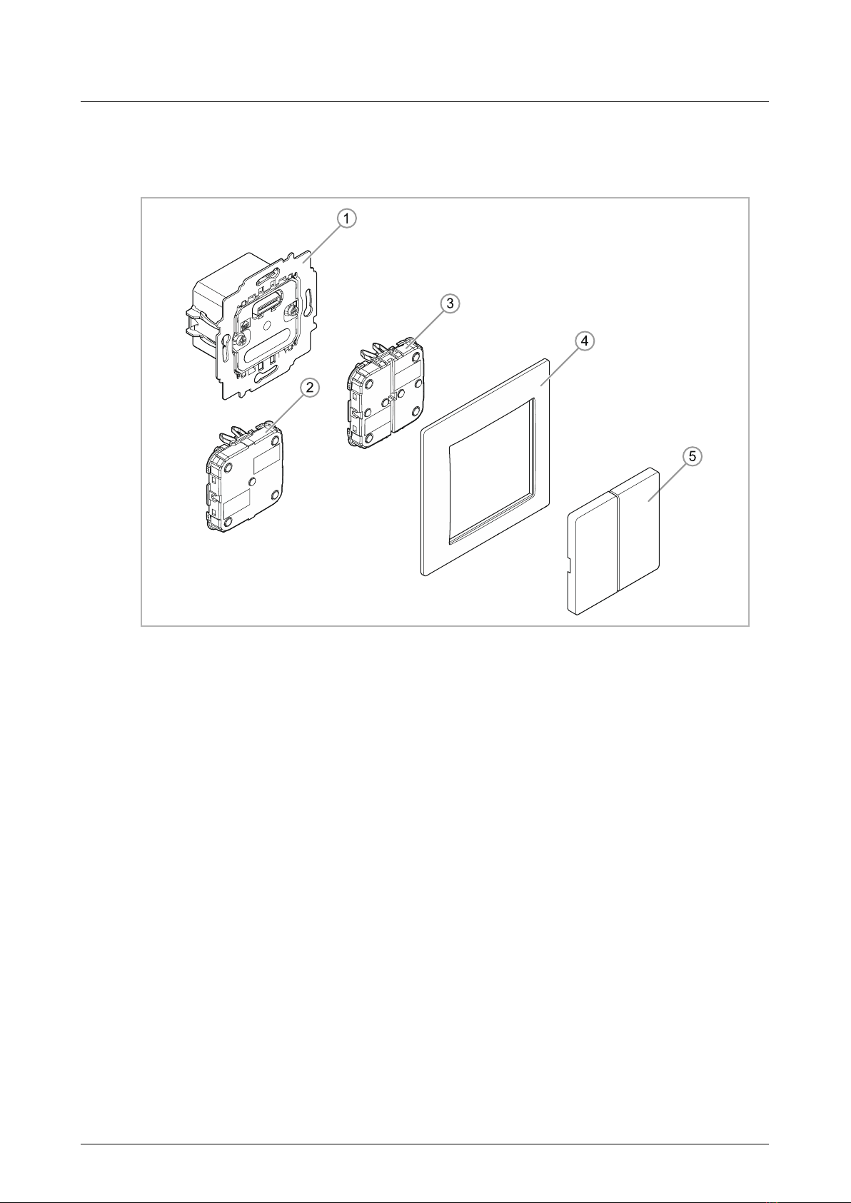
3.1
Scope of supply.....................................................................................................................................8
3.2
Overview of types..................................................................................................................................8
3.3
Functions ...............................................................................................................................................8
3.4
Device overview ....................................................................................................................................9
4
Technical data.................................................................................................................................................10
4.1
Dimensional drawings.........................................................................................................................10
5
Connection and installation ............................................................................................................................11
5.1
Planning instructions...........................................................................................................................11
5.2
Safety instructions ...............................................................................................................................12
5.3
Circuit diagrams ..................................................................................................................................13
5.4
Installation............................................................................................................................................14
6
Commissioning................................................................................................................................................16
6.1
Coupling of wireless devices with the System Access Point ............................................................17
6.1.1
Resetting the wireless device to the factory settings......................................................................17
6.2
Allocation of devices and definition of channels................................................................................19
6.2.1
Add device .......................................................................................................................................19
6.3
Setting options per channel ................................................................................................................24
6.3.1
Parameter settings of 1/1gang sensor/blind actuator.....................................................................25
6.3.2
Parameter settings of 2/1gang sensor/blind actuator.....................................................................29
6.4
Links.....................................................................................................................................................30
6.4.1
Linking actuator and sensor ............................................................................................................30
6.4.2
Linking an actuator with an additional sensor.................................................................................31
7
Update .............................................................................................................................................................32
8
Operation.........................................................................................................................................................33
9
Maintenance....................................................................................................................................................34
9.1
Cleaning...............................................................................................................................................34
9.2
Diagnosis of faults...............................................................................................................................35
10
Notes ...............................................................................................................................................................36
11
Index ................................................................................................................................................................37

Information on the manual
Product manual 2CKA001473B9187
│3
1 Information on the manual
Please read this manual carefully and observe the information it contains. This will assist you in
preventing injuries and damage to property, and ensure both reliable operation and a long
service life for the device.
Please keep this manual in a safe place.
If you pass the device on, also pass on this manual along with it.
Busch-Jaeger accepts no liability for any failure to observe the instructions in this manual.
If you require additional information or have questions about the device, please contact Busch-
Jaeger or visit our Internet site at:
www.busch-jaeger.de/freeathome

Safety
Product manual 2CKA001473B9187
│4
2 Safety
The device has been constructed according to the latest valid regulations governing technology
and is operationally reliable. It has been tested and left the factory in a technically safe and
reliable state.
However, residual hazards remain. Read and adhere to the safety instructions to prevent
hazards of this kind.
Busch-Jaeger accepts no liability for any failure to observe the safety instructions.
2.1 Information and symbols used
The following Instructions point to particular hazards involved in the use of the device or provide
practical instructions:
Danger
Risk of death / serious damage to health
– The respective warning symbol in connection with the signal word "Danger"
indicates an imminently threatening danger which leads to death or serious
(irreversible) injuries.
Warning
Serious damage to health
– The respective warning symbol in connection with the signal word "Warning"
indicates a threatening danger which can lead to death or serious
(irreversible) injuries.
Caution
Damage to health
– The respective warning symbol in connection with the signal word "Caution"
indicates a danger which can lead to minor (reversible) injuries.
Attention
Damage to property
– This symbol in connection with the signal word "Attention" indicates a
situation which could cause damage to the product itself or to objects in its
surroundings.
NOTE
This symbol in connection with the word "Note" indicates useful tips and
recommendations for the efficient handling of the product.
This symbol alerts to electric voltage.

Safety
Product manual 2CKA001473B9187
│5
2.2 Intended use
This device is a sensor/actuator unit for decentralized flush-mounted installation.
The device is intended for the following:
■Operation according to the listed technical data
■Installation in dry interior rooms and suitable flush-mounted boxes
■Use with the connecting options available on the device
The intended use also includes adherence to all specifications in this manual.
2.3 Improper use
Each use not listed in Chapter 2.2 “Intended use“ on page 5 is deemed improper use and can
lead to personal injury and damage to property.
Busch-Jaeger is not liable for damages caused by use deemed contrary to the intended use of
the device. The associated risk is borne exclusively by the user/operator.
The device is not intended for the following:
■Unauthorized structural changes
■Repairs
■Outdoor use
■The use in bathroom areas
2.4 Target group / Qualifications of personnel
Installation, commissioning and maintenance of the device must only be carried out by trained
and properly qualified electrical installers.
The electrical installer must have read and understood the manual and follow the instructions
provided.
The electrical installer must adhere to the valid national regulations in his/her country governing
the installation, functional test, repair and maintenance of electrical products.
The electrical installer must be familiar with and correctly apply the "five safety rules" (DIN VDE
0105, EN 50110):
1. Disconnect
2. Secure against being re-connected
3. Ensure there is no voltage
4. Connect to earth and short-circuit
5. Cover or barricade adjacent live parts

Safety
Product manual 2CKA001473B9187
│6
2.5 Safety instructions
Danger - Electric voltage!
Electric voltage! Risk of death and fire due to electric voltage of 100 … 240 V.
Dangerous currents flow through the body when coming into direct or indirect
contact with live components. This can result in electric shock, burns or even
death.
■Work on the 100 … 240 V supply system may only be performed by
authorised and qualified electricians.
■Disconnect the mains power supply before installation or dismantling.
■Never use the device with damaged connecting cables.
■Do not open covers firmly bolted to the housing of the device.
■Use the device only in a technically faultless state.
■Do not make changes to or perform repairs on the device, on its components
or its accessories.
Caution! - Risk of damaging the device due to external factors!
Moisture and contamination can damage the device.
■Protect the device against humidity, dirt and damage during transport,
storage and operation.
2.6 Environment
Consider the protection of the environment!
Used electric and electronic devices must not be disposed of with domestic
waste.
– The device contains valuable raw materials which can be recycled.
Therefore, dispose of the device at the appropriate collecting depot.
All packaging materials and devices bear the markings and test seals for proper disposal.
Always dispose of the packaging material and electric devices and their components via the
authorized collecting depots and disposal companies.
The products meet the legal requirements, in particular the laws governing electronic and
electrical devices and the REACH ordinance.
(EU Directive 2012/19/EU WEEE and 2011/65/EU RoHS)
(EU REACH ordinance and law for the implementation of the ordinance (EC) No.1907/2006).

Setup and function
Product manual 2CKA001473B9187
│7
3 Setup and function
Fig. 1: Product overview
[1] Flush-mounted insert
[2] Sensor für Sensor/Jalousieaktor 1/1-fach
[3] Sensor for sensor/blind actuator, 2/1-gang
[4] Cover frame (not included in scope of delivery)
[5] Rocker (not included in scope of delivery)
This device is a sensor/blind actuator unit for decentralized flush-mounted installation. The
devices serve for controlling blind motors (e.g. sun protection applications) and are pre-
programmed accordingly (button top/bottom: up/down; left rocker). However, this pre-
configuration can be adjusted as required. Also air vents, gates and windows can be controlled.
Sensor and actuator are combined in a flush-mounted insert [1].
After connecting the load, it can be switched directly on the control element.
Additional product features:
■Green LEDs as light for orientation and status indication
■Exchangeable rockers with the corresponding icons

Setup and function
Product manual 2CKA001473B9187
│8
3.1 Scope of supply
The scope of supply only contains the flush-mounted insert [1] and the sensor [2 or 3].
It must still be completed with a suitable rocker [5] and a cover frame [4].
Note
■Depending on their use, the rockers can be selected with different printing.
Additional information about the switch ranges is available in the electronic
catalogue (www.busch-jaeger-katalog.de).
3.2 Overview of types
Article no. Product name Sensor channels
Actuator
channels
Switching load
6213/1.1-WL
Sensor/blind
actuator, 1/1gang,
wireless
1
1
4 A
cosϕ= 0.5
6213/1.1-WL
Sensor/blind
actuator, 2/1gang,
wireless
2
1
4 A
cosϕ= 0.5
Table 1: Overview of types
3.3 Functions
The following table provides an overview of the possible functions and applications of the
device:
Icon of the user
interface Information
Name: Sensor
Type: Sensor
Made available by:
Sensor/blind actuator
Function: Control element for the control of
free@home functions
Name:
Blind actuator
Type:
Actuator
Made available by: Sensor/blind actuator
Function: Switches connected loads
Table 2: Overview of functions

Setup and function
Product manual 2CKA001473B9187
│9
3.4 Device overview
134
2
Fig. 2: Overview of devices Sensor/blind actuator, 1/1gang; 2/1gang, wireless (without sensors)
[1] Phase sensing L
[2] Mark TOP
[3] Terminal strip for sensor
[4] Bottom terminal block
Fig. 3: Sensors
[1] Sensor for Sensor/blind actuator, 1/1gang, wireless
[2] Sensor for Sensor/blind actuator, 2/1gang, wireless

Technical data
Product manual 2CKA001473B9187
│10
4 Technical data
Designation Value
Operating voltage 230 V AC, 50/60 Hz
Connection
L, N (option), inputs and outputs non-
floating
Screw-type terminal:
2 x 2.5 mm² rigid;
2 x 1.5 mm² flexible
Claw With protective cover and reset
(removable)
Transmission protocol free@home wireless
Transmission frequency 2.400 - 2.483 GHz
Maximum transmission power
WL (wireless) < 15 dBm
Power consumption < 1 W
Maximum load 4 A Ⓜ
Protection type IP20
Ambient temperature -5°C - +45°C
Storage temperature -20°C - +70°C
Table 3: Technical data
4.1 Dimensional drawings
NOTE
All dimensions are specified in mm. All device types listed in this manual
have the same dimensions.
71
51
51
71
32
45
Fig. 4: Dimensions of all described device types (all dimensions in mm)

Connection and installation
Product manual 2CKA001473B9187
│11
5 Connection and installation
5.1 Planning instructions
Note
Planning and application instructions for the system are available in system
manual for Busch-free@home®. This can be downloaded via www.busch-
jaeger.de/freeathome.
Note
Transmitter and receiver communicate via radio control. The transmission range
depends on the structural conditions. Walls and ceilings, especially steel
reinforcements or metal claddings, reduce the transmission range. The distance
of components to each other and to other transmitters that also emit high-
frequency signals (e.g. computers, audio and video systems) should be at least
1 m.

Connection and installation
Product manual 2CKA001473B9187
│12
5.2 Safety instructions
Danger - Electric shock due to short-circuit!
Risk of death due to electrical voltage of 100 … 240 V during short-circuit in the
low-voltage conduit.
– Low-voltage and 100 … 240 V conduits must not be installed together in a
flush-mounted box!
– Observe the spatial division during installation (> 10 mm) of SELV electric
circuits to other electric circuits.
– If the minimum distance is insufficient, use electronic boxes and insulating
tubes.
– Observe the correct polarity.
– Observe the relevant standards.
Danger - Electric voltage!
Install the device only if you have the necessary electrical engineering
knowledge and experience.
■Incorrect installation endangers your life and that of the users of the
electrical system.
■Incorrect installation can cause serious damage to property, e.g. due to fire.
The minimum necessary expert knowledge and requirements for the installation
are as follows:
■Apply the "five safety rules" (DIN VDE 0105, EN 50110):
1. Disconnect
2. Secure against being re-connected
3. Ensure there is no voltage
4. Connect to earth and short-circuit
5. Cover or barricade adjacent live parts.
■Use suitable personal protective clothing.
■Use only suitable tools and measuring devices.
■Check the type of supply network (TN system, IT system, TT system) to
secure the following power supply conditions (classic connection to ground,
protective earthing, necessary additional measures, etc.).
■Observe the correct polarity.

Connection and installation
Product manual 2CKA001473B9187
│13
5.3 Circuit diagrams
L
N
10 A
LN12
M
AB
Fig. : Electrical connection
[A] Up
[B] Down

Connection and installation
Product manual 2CKA001473B9187
│14
5.4 Installation
Note
The devices have been prepared for installing in flush-mounted boxes in
connection with the corresponding mounting plate. The device insert has already
been inserted in the mounting plate.
To install the device, perform the following steps:
Note
The sensor must be pulled off the flush-mounted insert before mounting!
Note
Observe correct wiring!
1. Turn the device into the correct
installation position [1].
2. Connect the 230 V power cord to the
bottom terminal block [2].
Observe Chapter 5.3 “Circuit diagrams“
on page 13.
3. Insert the device into the flush-
mounted box and screw it on.
Abb. 5: Connection and installation
4. Attach the cover (rocker; example
shows only a 1gang rocker) to the
sensor.
Fig. 6: Mounting the cover
5. Mount the cover frame.
Fig. 7: Mounting the cover fame

Connection and installation
Product manual 2CKA001473B9187
│15
6. Attach the cover (with mounted
sensor) to the flush-mounted insert.
Observe the correct position of the
sensor connection [1].
Fig. 8: Mounting the sensor

Commissioning
Product manual 2CKA001473B9187
│16
6 Commissioning
Commissioning of the device is always carried out via the Web-based surface of the System
Access Point. It is assumed that the basic commissioning steps of the overall system have
already been carried out. Knowledge about the Web-based commissioning software of the
System Access Point is assumed.
The System Access Point establishes the connection between the free@home participants and
the smartphone, tablet or PC. The System Access Point is used to identify and program the
participants during commissioning.
When energized, a device that has not been programmed is in programming mode for 30
minutes and can be logged into the system. Programmed devices share information about their
type and supported functions with the System Access Point.
During initial commissioning all devices are given a universal name (e.g. sensor/switch actuator,
sensor/dimming actuator, sensor/blind actuator, room temperature controller, movement
detector, etc.). The installer must change this name within the commissioning process to a
name practical and specific for the system (in case of an actuator, e.g. to "Living room ceiling
light").
The devices must be parameterised for the use of additional functions.
Note
General information about commissioning and parameterization is available in
the Busch-free@home®system manual.

Commissioning
Product manual 2CKA001473B9187
│17
6.1 Coupling of wireless devices with the System Access Point
free@home wireless devices must first be coupled with the System Access Point before they
can be used in a project. The devices exchange a security key during the coupling process.
Communication between devices is carried out encrypted after coupling and they are firmly
connected with the System Access Point. Coupled devices cannot be connected with a different
System Access Point. They must first be reset to the factory settings.
Carry out the following steps to couple one or several devices with the system:
1. Install the free@home wireless device(s).
2. Use your smartphone, tablet or PC to call up the user interface of the System Access Point
that is ready for use.
3. Switch on the mains power supply of the free@home wireless devices.
The devices are now in programming mode for 30 minutes.
Fig 9: Coupling wireless devices with the System Access Point
4. In the user interface of the System Access Point select "System settings" "free@home-
Wireless settings" "Search for wireless devices".
The System Access Point consecutively scans all free@home wireless devices. Devices
that are in programming mode are integrated automatically into the system. The scanning
process ends 10 minutes after the last device has been integrated.
Integrated devices are listed in the "Device list" of the user interface.
5. Use the serial numbers to check whether all installed devices have been found.
If a device has not been found, reset it to the factory settings and start a new scanning
process.
Possible reasons for not finding devices:
■The device is not in programming mode.
■The 30-minute programming time has expired.
■The device has already been coupled with a different system.
6.1.1 Resetting the wireless device to the factory settings
1. De-energize the free@home wireless device.

Commissioning
Product manual 2CKA001473B9187
│18
2. Keep the button at the bottom left pressed.
3. Re-energize the device.
The LED flashes slowly for 10 seconds, then fast for 5 seconds and then goes out.
The factory settings are restored and the device can now be programmed again.
Note
Devices which are already in factory settings are not reset again. The LED
remains out in step 3.

Commissioning
Product manual 2CKA001473B9187
│19
6.2 Allocation of devices and definition of channels
The devices connected to the system must be identified, i.e. they are allocated to a room
according to their function and are given a practical name.
The allocation is made via the allocation function of the Web-based
user interface of the System Access Point.
6.2.1 Add device
1. In the "Add devices" bar select the desired application and pull it via drag-and-drop into the
floor plan.
Fig. 10: Dragging the application from the add bar
A pop-up window opens which lists all the devices that are connected to the bus and suitable for
the selected application (e.g. all blind actuators, if the blind application has been selected).

Commissioning
Product manual 2CKA001473B9187
│20
Fig. 11: Pop-up window with the suitable devices
Table of contents
Other Busch-Jaeger Controllers manuals
Popular Controllers manuals by other brands

Rotork Fairchild
Rotork Fairchild PAX1 user manual

DROPSA
DROPSA ADVANCED LUBRICATION CONTROLLER INSTRUCTION AND PRODUCT DATA SHEET

KiSS
KiSS KIPR Link manual

Automationdirect.com
Automationdirect.com D4-454 PLC user manual

Carel
Carel ir33+ quick start guide

Yisutongma Network Technology
Yisutongma Network Technology ESM-9013 instruction manual

Liebert
Liebert AC4 user manual

Isimet
Isimet LA Series Installation, Operations, Start-up and Maintenance Instructions

Truma
Truma SecuMotion Operating instructions & installation instructions

Instrutech
Instrutech VGC301A user manual

BRV
BRV ModvlvS Logico Installation and operating instructions

vissonic
vissonic VIS-CATC-B user manual