4
BEFORE USE
Read all instructions carefully before attempting to
assemble or operate these pumps. Most malfunctions in
new equipment are the result of improper operation and/or
improper set-up assembly.
Visually inspect all components for shipping damage. Do
not use if any damage is found.
Note:
E-Pumps are shipped without hydraulic oil filled.
Add oil before starting motor and operation.
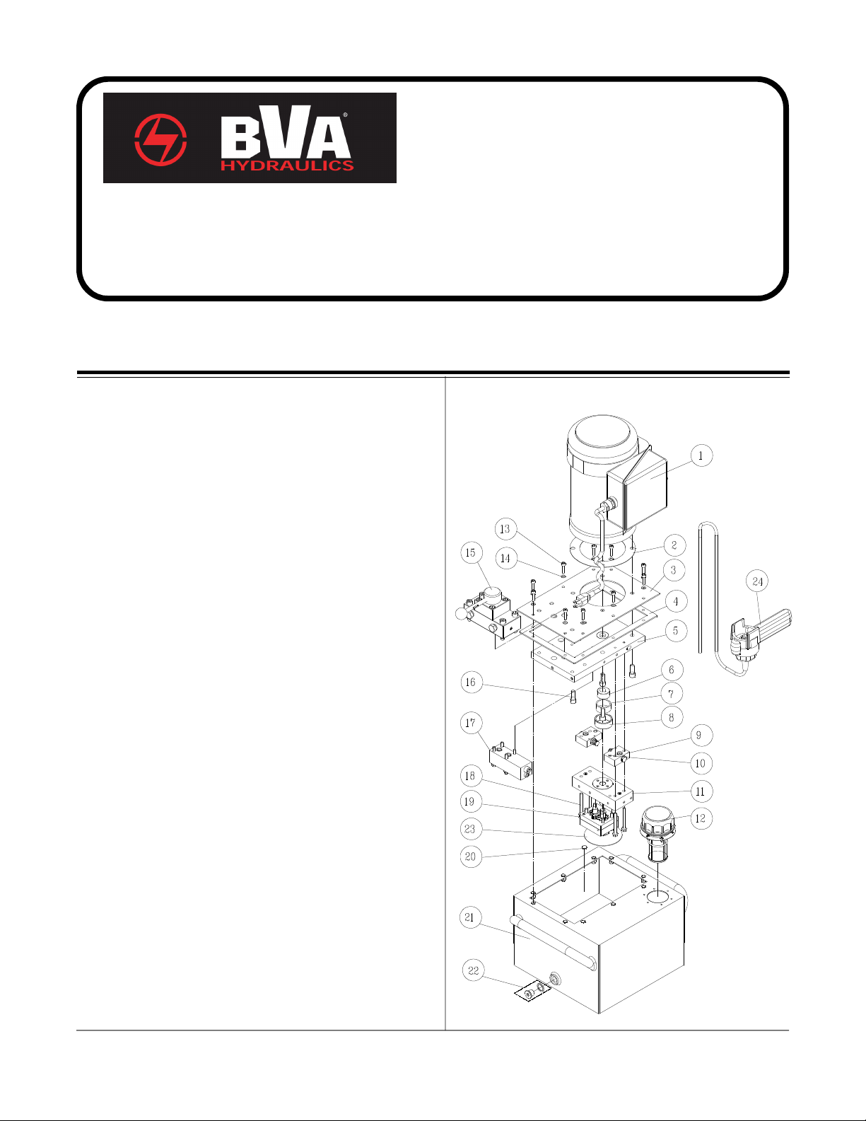
Familiarize yourself with the specification and illustrations
in this owner manual. Use service parts drawing on page 8
thru 11 as reference of location and assembly.
Electrical Connections:
1. Compare motor nameplate against power availability to
prevent motor burnout or dangerous electrical
overloading.
2. The motors are wired for 110 volts unless otherwise
specified, and are supplied with a plug and cord.
3.Try to minimize the use of long extension cord and make
sure the wire size is adequate and with grounded
connections.
Hydraulic Connections:
1. Make sure to use correct type of hydraulic oil specified by
the manufacturer. Check and make sure the oil level in
reservoir is at about 2" from top of reservoir plate, with
cylinders retracted and motor off.
2. Use of pressure gauge is strongly recommended. Attach
a pressure gauge between the pump and cylinder to
monitor pressure on cylinder.
3. Make sure coupler, hose, valve, gauge are tighten securely
to prevent accidental removal of components while in
use. Hoses shall not be kinked or twisted.
Note
: Always secure threaded port connections with non-
hardening pipe thread compound. Take care not to introduce
compound into port orifices.
4. Do not exceed the rated capacity of the equipment
connected to the pump. Use larger capacity of cylinders
if necessary.
The pump's maximum working pressure is 10,000 PSI.
Make sure that all hydraulic equipment such as cylinders,
hoses, coupler and etc. used with this pump are rated at
10,000 PSI operating pressure
.
OPERATION
ALWAYS monitor pressure, load or position using
suitable equipment. Pressure may be monitored by means
of an optional manifold and gauge. Load may be monitored
by means of a load cell and digital indicator. Correct
application position can only be determined by the operator
of the equipment.
1. Check oil level, add oil if necessary.
2. Make sure system fittings and connections are tight and
leak free.
3. Place control valve lever in the middle ( eutral/Hold)
position to prevent accidental lifting or moving of load.
4. To
start
the motor:
(a) For PE series, turn the O /OFF switch located on the
control box to O position.
(b) For PEW series, press and hold on to the switch of the
remote pendant.
5. Let the pump idle for a few minutes before put into
operation.
Note.
To ensure smooth operation, bleed air from the system
by fully advancing and retracting the cylinder several times.
6. Use the control valve lever to control the direction of fluid
flow. These pumps are equipped with a 4-way 3-position
valve. Refer to figure 4(a) on page 5 for the flow path.
7. Always monitor the pressure, load and position.
8. Shift the control valve, until desired pressure, load or
position is read.
Note:
Do not continue to operate pump after cylinder
plunger is fully extended or retracted.
9. To
turn off
the motor:
(a) For PE series, turn the O /OFF switch on the control
box to OFF position.
(b) For PEW series, the motor will stop when the switch is
released.
10. Depressurize all connections before disconnect.
Note:
Control valves on these pumps are 4-way, 3- position,
for use with double acting cylinders. If your application require
a 3-way setting shown in figure 4(b), it can be changed by an
authorized BVA Service Center. If you have any doubt, please
consult BVA Technical Service 888-332-6419.
!
!