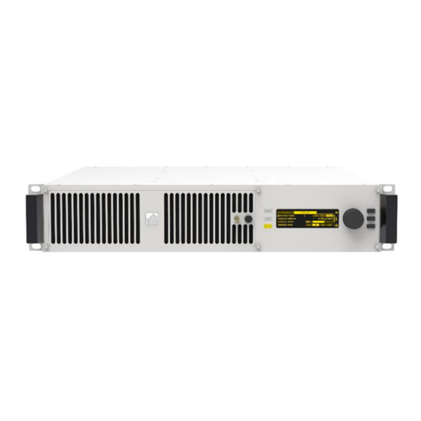
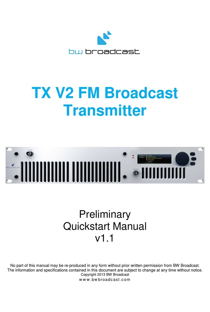
BW Broadcast TX V2 User manual

V2 FM TRANSMITTERS
TECHNICAL MANUAL
Document rev 3.2
The software in the transmitter is upgradeable. This manual may refer to an older software version. Note that
previous versions of software may not have all of the features described in the manual. To check the latest
software go to www.bwbroadcast.com/downloads
No part of this manual may be re-produced in any form without prior written permission from BW Broadcast. The
information and specifications contained in this document is subject to change at any time without notice.
©2014 BW Broadcast
www.bwbroadcast.com

Contents
I Introduction 8
1 TheTX-V2 ......................................... 9
2 Warranty ......................................... 10
3 Safety ........................................... 12
4 FrontandRearPanels.................................. 16
4.1 1U(TX5,TX30,TX50)................................. 16
4.2 2U(TX300,TX600) .................................. 17
4.3 2U(TX1000,TX1500)................................. 18
4.4 3U(TX2500) ..................................... 19
5 UserInterface ...................................... 20
5.1 InputInterface ................................... 20
5.1.1 Navigatingthemenu............................. 20
5.1.2 Editingaparameter ............................. 20
5.1.3 Textfields .................................... 20
5.2 Display ........................................ 21
5.2.1 StatusBox.................................... 21
5.2.2 MenuBox.................................... 22
5.2.3 Meters...................................... 23
2

II Initial Setup and connections 24
6 Installation ........................................ 25
6.1 QuickStart...................................... 25
6.2 ExamplesofUse................................... 26
6.2.1 Transmitter with an external RDS encoder and internal audio pro-
cessing ..................................... 26
6.2.2 Transmitter with an external audio processor . . . . . . . . . . . . . . . 27
6.2.3 Transmitter with an external audio processor and RDS (In Line Con-
nection)..................................... 28
6.2.4 Transmitter with an external audio processor and RDS (Side Chain
Connection) .................................. 29
III System Configuration 31
7 OperationGuide .................................... 32
7.1 RFSettings ...................................... 32
7.1.1 BasicSetup................................... 32
7.1.2 PowerScheduler ............................... 32
7.2 AudioSettings.................................... 33
7.3 Triggers........................................ 33
7.4 Alarms ........................................ 34
7.5 System ........................................ 35
7.5.1 RealTimeClock ................................ 35
7.5.2 UnitInformation ................................ 35
7.5.3 ScreenSaver.................................. 36
7.5.4 Users....................................... 36
7.5.5 Ethernet..................................... 36
7.5.6 E-Mail ...................................... 37
7.5.7 HTTP ....................................... 38
7.5.8 Telnet ...................................... 38
3

7.5.9 RS232 ...................................... 39
7.5.10Log........................................ 39
7.5.11Diagnostics................................... 41
7.5.12About ...................................... 41
7.5.13Reboot ..................................... 41
7.5.14FactoryReset.................................. 41
7.6 WebRemote .................................... 41
7.6.1 Autentication ................................. 41
7.6.2 Web Remote Interface . . . . . . . . . . . . . . . . . . . . . . . . . . . . 42
7.7 Text Based Access (Telnet or Serial RS232) . . . . . . . . . . . . . . . . . . . 44
7.7.1 Commands................................... 44
7.8 WebAPI ....................................... 45
7.8.1 Authentication................................. 46
7.8.2 SettingAParameter ............................. 46
7.8.3 ReadingParameters ............................. 47
7.8.4 ReadingMeters ................................ 48
7.8.5 Readinglogfiles................................ 48
7.9 Parameters ..................................... 49
7.9.1 RFSettings ................................... 49
7.9.2 AudioSettings ................................. 51
7.9.3 Triggers ..................................... 52
7.9.4 Alarms...................................... 53
7.9.5 System...................................... 54
8 ParameterGuide .................................... 62
8.1 RFSettings ...................................... 62
8.1.1 Frequency ................................... 62
8.1.2 Power ...................................... 62
8.1.3 MPXSource................................... 62
4

8.1.4 FSK (for translators in the USA) . . . . . . . . . . . . . . . . . . . . . . . . 63
8.1.5 RFMuteonSilence .............................. 63
8.1.6 RFMute(Manual)............................... 63
8.1.7 PowerScheduler ............................... 63
8.2 AudioSettings.................................... 64
8.2.1 MPXSource................................... 64
8.2.2 AudioInput................................... 64
8.2.3 ProcessingPreset ............................... 65
8.2.4 Pre-emphasis.................................. 65
8.3 Triggers........................................ 65
8.3.1 Enable...................................... 65
8.3.2 Action...................................... 66
8.3.3 Sende-mail................................... 66
8.3.4 (ON)Message................................. 66
8.4 Alarms ........................................ 67
8.4.1 Type....................................... 67
8.5 System ........................................ 70
8.5.1 Date....................................... 70
8.5.2 Time ....................................... 71
8.5.3 Uptime ..................................... 71
8.5.4 Location .................................... 71
8.5.5 Contact..................................... 71
8.5.6 ScreenSaver.................................. 71
8.5.7 ScreenLock .................................. 71
8.5.8 ScreenLockCode .............................. 71
8.5.9 Users....................................... 71
8.5.10Ethernet..................................... 72
8.5.11E-Mail ...................................... 73
5

8.5.12HTTP ....................................... 74
8.5.13Telnet ...................................... 74
8.5.14RS232 ...................................... 75
8.5.15Log........................................ 75
8.5.16Diagnostics................................... 76
8.5.17About ...................................... 76
8.5.18Reboot ..................................... 77
8.5.19FactoryReset.................................. 77
IV Troubleshooting 78
9 V2 FM Transmitter Troubleshooting Guide . . . . . . . . . . . . . . . . . . . . . . 79
V Technical Specifications 81
10 TechnicalSpecifications ................................ 82
10.1 Common Specifications . . . . . . . . . . . . . . . . . . . . . . . . . . . . . . 82
10.1.1RF......................................... 82
10.1.2AudioandMPXI/O .............................. 82
10.1.3Stereo...................................... 82
10.1.4Limiter...................................... 83
10.1.5Other ...................................... 83
10.1.6 Temperature Protection . . . . . . . . . . . . . . . . . . . . . . . . . . . 83
10.1.7VSWRProtection................................ 83
10.2 Model-Specific Specifications . . . . . . . . . . . . . . . . . . . . . . . . . . 84
10.2.1TX5V2...................................... 84
10.2.2TX30V2 ..................................... 84
10.2.3TX50V2 ..................................... 85
10.2.4TX300V2..................................... 86
6

10.2.5TX600V2..................................... 86
10.2.6TX1000V2.................................... 87
10.2.7TX1500V2.................................... 87
10.2.8TX2500V2.................................... 88
7

Part I
Introduction
8

1
The TX-V2
The BW Broadcast TX-V2 is the latest development in a high specification range of FM trans-
mitters over 15 years in the making.
Its broadband ”no-tune” design allows 87.5 - 108MHz operation without requiring tuning or
calibration. The inclusion of four-band DSPX audio processing means stations without a ded-
icated processor sound great, right out of the box. Those who already have external pro-
cessing benefit from BW Broadcast’s unique dual-loop virtual VFO exciter and field proven
ultra-low distortion modulator integrated into a great performing, highly stable FM transmis-
sion system.
Features such as slide-in power supplies, and unique solder-free Gold-Clamp transistors (on
most models) make in-field maintenance simple.
A high resolution OLED screen displays RF, audio and system parameters. The control wheel
and three front panel buttons allow easy navigation of the menus. Help tips for every param-
eter make setup simple.
Every TX-V2 Transmitter features a LAN connection for Ethernet local or remote control. The
LAN connection also supports SNMP, telnet, and email alerts via either SMTP or BW Broad-
cast’s mail server. Where a LAN connection is not available, the RS232 connection can be
used.
Intelligent alarms and email alerts ensure busy engineers can manage their stations with min-
imal intervention. A real time clock and comprehensive logging is available for those who
like to see more detailed status. Also present are 4 rear panel opto-isolated triggers that al-
low external equipment to control the transmitter.
It is advised that this manual is read to learn all of the advanced features of the TX-V2 Trans-
mitter.
9

2
Warranty
Please ensure the Warranty Registration process is completed upon receipt of this product.
To do so go to www.bwbroadcast.com/warranty with your product’s serial number to hand.
BW Broadcast warrants the mechanical and electronic components of this product to be
free of defects in material and workmanship for a period of two (2) years* from the original
date of purchase, in accordance with the warranty regulations described below. If the prod-
uct shows any defects within the specified warranty period that are not due to normal wear
and tear and/or improper handling by the user, BW Broadcast shall, at its sole discretion, ei-
ther repair or replace the product. If the warranty claim proves to be justified, the product will
be returned to the user freight prepaid. Warranty claims other than those indicated above
are expressly excluded.
Return authorisation number: To obtain warranty service, the buyer (or his authorized
dealer) must contact BW Broadcast during normal business hours BEFORE returning the prod-
uct. All inquiries must be accompanied by a description of the problem. BW Broadcast will
then issue a return authorization number. Subsequently, the product must be returned in its
original shipping carton, together with the return authorization number to the address indi-
cated by BW Broadcast. Shipments without freight prepaid will not be accepted.
Warranty regulations: Any product deemed eligible for repair or replacement by BW Broad-
cast under the terms of this warranty will be repaired or replaced within 30 days of receipt
of the product at BW Broadcast. If the product needs to be modified or adapted in order
to comply with applicable technical or safety standards on a national or local level, in any
country which is not the country for which the product was originally developed and man-
ufactured, this modification/- adaptation shall not be considered a defect in materials or
workmanship. The warranty does not cover any such modification/adaptation, irrespective
of whether it was carried out properly or not. Under the terms of this warranty, BW Broadcast
shall not be held responsible for any cost resulting from such a modification/adaptation. Free
inspections and maintenance/repair work are expressly excluded from this warranty, in par-
ticular, if caused by improper handling of the product by the user. This also applies to defects
caused by normal wear and tear, in particular, of faders, potentiometers, keys/buttons and
similar parts. Damages/defects caused by the following conditions are not covered by this
warranty: Misuse, neglect or failure to operate the unit in compliance with the instructions
given in BW Broadcast user or service manuals. Connection or operation of the unit in any
way that does not comply with the technical or safety regulations applicable in the country
where the product is used. Damages/defects caused by force majeure or any other con-
dition that is beyond the control of BW Broadcast. Any repair or opening of the unit carried
out by unauthorized personnel (user included) will void the warranty. If an inspection of the
product by BW Broadcast shows that the defect in question is not covered by the warranty,
the inspection costs are payable by the customer. Products which do not meet the terms of
this warranty will be repaired exclusively at the buyer’s expense. BW Broadcast will inform the
buyer of any such circumstance.
10

Warranty transferability: This warranty is extended exclusively to the original buyer (cus-
tomer of retail dealer) and is not transferable to anyone who may subsequently purchase this
product. No other person (retail dealer, etc.) shall be entitled to give any warranty promise
on behalf of BW Broadcast.
Claims for damages: Failure of BW Broadcast to provide proper warranty service shall not
entitle the buyer to claim (consequential) damages. In no event shall the liability of BW
Broadcast exceed the invoiced value of the product.
Other warranty rights and national law: This warranty does not exclude or limit the buyer’s
statutory rights provided by national law, in particular, any such rights against the seller that
arise from a legally effective purchase contract. The warranty regulations mentioned herein
are applicable unless they constitute an infringement of national warranty law.
*Warranty period can be extended for an additional cost at point of purchase
11

3
Safety
MAINS VOLTAGE: TX5 V2 - TX600 V2 operate from an AC
power source between 110 and 240 V.
TX1000 V2 - TX2500 V2 operate from a power source be-
tween 220 and 240 V. WARNING: To avoid damage DO
NOT CONNECT TO 110V.
These power supplies use a C19 plug. The wiring format is:
Ground - GREEN/YELLOW
Neutral - BLUE
Live - BROWN
SWITCHED MODE POWER SUPPLY HAZARD Please note that the power supply units in this
equipment is of the switched mode variety and have lethal voltages present internally. The
switched mode supplies are universal input fully approved type. They are non serviceable
modules and should be fully replaced should they fail.
FUSES Only use fuses with the specified voltage and current ratings as stated on the back
panel. Failure to do so may increase the risk of equipment failure, shock and fire hazard.
R.F. The N type R.F. power output socket contains R.F. voltages which may burn or present
a shock. Please make sure that the equipment is connected to an adequately rated load or
antenna system while in operation.
TOXIC HAZARD This equipment includes R.F. components that may contain Beryllium oxide
which is a highly toxic substance that could be hazardous to health if inhaled or ingested.
Care should be taken when replacing or discarding such devices. Seek expert advice from
the manufacturer should you physically damage a device that contains Berillyium Oxide. The
main R.F. output power transistor contains Beryllium oxide.
OTHER SAFETY CONSIDERATIONS Do not operate this equipment in the presence of
flammable gases, fumes or liquids Do not expose this equipment to rain or water.
12

CE CONFORMANCE This device complies with the re-
quirements of the 1995/5/EC Radio and Telecommunica-
tions Terminal Equipment (R&TTE). The equipment will meet
or exceed the following standards: EN 60215:1996 (Safety
Requirements for Radio Transmitting Equipment), EN 301
489-11 (ERM/EMC for Radio Equipment, Part 11 Specific
Conditions for FM Transmitters), EN 302 018-2 ERM (Transmitting Equipment for FM Radio
Broadcasting service)
The operating frequencies of this transmitter may not be harmonised in the intended coun-
tries of use. The user must obtain a license before using the product in the intended country
of use. Ensure respective country licensing requirements are complied with. Limitations of use
can apply in respect of operating frequency, transmitter power and/or channel spacing.
WEEE COMPLIANCE BW Broadcast Ltd is registered with Northern
Compliance PCS number WEE/P3438PR/ SCH and has been issued
with WEE/FA0268RX as its unique producer ID by the appropriate en-
vironment agency. BW Broadcast Ltd full comply with it explicit re-
sponsibilities, subject to WEEE Collections Policy outlined in their Gen-
eral Terms and conditions of Sale, when it sells Electrical and Elec-
tronic Equipment (EEE) to B2B customers in the UK and EU.
This appliance has been designed and manufactured with high
quality materials and components that can be recycled and reused.
Electronic appliances are liable to contain parts that are necessary in
order for the system to work properly but which can become a health
and environmental hazard if they are not handled and disposed of in
the proper way. Consequently, please do not throw your inoperative
appliance with the household waste. Having purchased this appliance it is your responsibility
to dispose of this equipment appropriately.
CAUTION: To reduce the risk of electrical shock, do not remove the cover. No user service-
able parts inside. refer servicing to qualified personnel.
WARNING: To reduce the risk of fire or electrical shock, do not expose this appliance to rain
or moisture.
DETAILED SAFETY INSTRUCTIONS:
All the safety and operation instructions should be read before the appliance is operated.
Retain Instructions: The safety and operating instructions should be retained for future refer-
ence.
13

Heed Warnings: All warnings on the appliance and in the operating instructions should be
adhered to.
Follow instructions: All operation and user instructions should be followed.
Water and Moisture: The appliance should not be used near water (e.g. near a bathtub,
washbowl, kitchen sink, laundry tub, in a wet basement, or near a swimming pool etc.).
The appliance should not be exposed to dripping or splashing and objects filled with liquids
should not be placed on the appliance.
Ventilation: The appliance should be situated so that its location or position does not inter-
fere with its proper ventilation. For example, the appliance should not be situated on a bed,
sofa rug, or similar surface that may block the ventilation openings, or placed in a built-in in-
stallation, such as a bookcase or cabinet that may impede the flow of air through the venti-
lation openings.
Heat: The appliance should be situated away from heat sources such as radiators, heat
registers, stoves, or other appliance (including amplifiers) that produce heat.
Power Source: The appliance should be connected to a power supply only of the type de-
scribed in the operating instructions or as marked on the appliance.
Grounding or Polarization: Precautions should be taken so that the grounding or polariza-
tion means of an appliance is not defeated.
Power-Cord Protection: Power supply cords should be routed so that they are not likely to
be walked on or pinched by items placed upon or against them, paying particular attention
to cords and plugs, convenience receptacles and the point where they exit from the appli-
ance.
Cleaning: The appliance should be cleaned only as recommended by the manufacturer.
Non-use Periods: The power cord of the appliance should be unplugged from the outlet
when left unused for a long period of time.
Object and Liquid Entry: Care should be taken so that objects do not fall and liquids are not
spilled into the enclosure through openings.
14

Damage Requiring Service: The appliance should be serviced by qualified service person-
nel when:
•The power supply cord or the plug has been damaged; or
•Objects have fallen, or liquid has been spilled into the appliance; or
•The appliance has been exposed to rain; or
•The appliance does not appear to operate normally or exhibits a marked change in
performance; or
•The appliance has been dropped, or the enclosure damaged.
Servicing: The user should not attempt to service the appliance beyond that is described in
the Operating Instructions. All other servicing should be referred to qualified service person-
nel.
15

4
Front and Rear Panels
4.1 1U (TX5, TX30, TX50)
16

4.2 2U (TX300, TX600)
17

4.3 2U (TX1000, TX1500)
18

4.4 3U (TX2500)
19

5
User Interface
5.1 Input Interface
The TX-V2 has an intuitive interface based around a pushable scroll wheel and three buttons.
Exit
Help
Meters
Push
to Enter
5.1.1 Navigating the menu
The menu is navigated by rotating the scroll wheel, pushing it in to open a submenu. Within
in a submenu, pressing exit will return to the parent menu.
5.1.2 Editing a parameter
To edit a parameter, first find it in the menu, highlight it and press enter. For most parameters
this will result in the parameter being highlighted (black text on a yellow background). The
value of the parameter can now be modified using touch sensitive wheel. When the correct
value is selected, press exit to take you back to menu-navigation mode.
Some parameters require a bit more space to edit (e.g. text fields). For these parameters, a
dialog box will pop up allowing more space to edit.
5.1.3 Text fields
When editing a text field, a dialog box will appear allowing modification of the full text. Press-
ing enter will toggle between two modes:
•Scrolling through the text: the selected character will have a yellow rectangle around
it.
•Modifying the current character: the character will be black on a yellow background.
When modifying a letter, one of the soft-keys will allow selection between the four char-
acter sets: lowercase letters, uppercase letters, numbers and symbols.
20
Other manuals for TX V2
1
Table of contents
Other BW Broadcast Transmitter manuals