BWT Fairland IPHCR15 User manual

1 / 18
2018/12 –B - Code : 33315
BWT FAIRLAND
INVERTER PLUS
Pompe à chaleur
IPHCR15 - IPHCR20 - IPHCR26 - IPHCR33
- IPHCR40 - IPHCR45 - IPHCR55 - IPHCR70
- IPHCR70T - IPHCR100T

2 / 18
2018/12 –B - Code : 33315
I. General product presentation and operating principal 23
II. Safety recommendations 23
III. Content 23
IV. Technical data and dimensions 24
V. Product installation 25
V.1 Siting 25
V.2 Support 26
V.3 Handling 26
V.4 Connection to the hydraulic circuit 26
V.5 Wiring 27
V.6 Heating priority 28
VI. Start up and operation 28
VII. Upkeep and maintenance 29
VII.1 –Shut down for winterizing 29
VII.2 –Technical inspections 30
VII.3 –Spares parts 30
VIII. Error messages 31
IX. Troubleshooting 33

3 / 18
2018/12 –B - Code : 33315
Warning:
a. Please read the following tips before installation, use and maintenance.
b. Installation, removal and maintenance must be carried out by qualified professional in accordance with
the instructions.
c. Gas leakage test must be done before and after installation.
1. Use
a. It must be installed or removed by professionals, and it is forbidden to dismantle and refit without
permission.
b. Don’t put obstacles before the air inlet and outlet of the heat pump.
2. Installation
a. This product must be kept away from any source of fire.
b. The installation can’t be in a closed environment or indoors, and must be kept well ventilated.
c. Vacuum completely before welding, welding can only be performed by qualified professional.

4 / 18
2018/12 –B - Code : 33315
d. Installation must be stopped if any gas leakage.
3. Transportation & Storage
a. Sealing is not allowed during transportation
b. Transporting goods at a constant speed is needed to avoid sudden acceleration or sudden braking, so as
to reduce the collision of goods.
c. The unit must be far away from any source of fire.
d. Storage place must be bright, wide, open and good ventilation, ventilation equipment is required.
4. Maintenance Notice
a. If maintenance or scrap is required, contact a qualified professional nearby.
b. Qualification requirement :
All operators who dispose gas must be qualified by valid certification which issued by professional
agency.
c. Please strictly comply with the requirement from manufacturer when maintenance or filling gas. Please
refer to the technical service manual.

5 / 18
2018/12 –B - Code : 33315
I. General product presentation and operating
Fairland Inverter water/ air heat pumps are purpose designed to heat or cool swimming pools. Performance
data is only guaranteed for this specific application.
Water / air heat pumps are an efficient inexpensive means of heating swimming pool water.
The device exploits the thermodynamic properties of heat transfer fluids when subjected to the well known
compression –expansion cycle: owing to its special properties, the refrigerant recovers calories from the
inexhaustible supply contained in ambient air, then, after compression and heating, transfers them to the
swimming pool water, thus heating it.
Given that a heat pump transfers heat extracted from outdoor air to the pool water, rather than creating heat
like a boiler or electrical heater a heat pump heats the pool water for 80 % less than the cost of heating by
other means.
Nevertheless, in order to further reduce pool heating costs. the pool should be covered with an isothermal
cover at night and. more generally. while the pool is not in use. The cover minimises evaporation from the
surface of the water the main source of heat loss.
Despite this, during the colder times of year, it may be necessary to run the heat pump continuously 24 hours
a day. This is not a cause for concern; heat pumps are designed to run 24 hours a day. Even under these
circumstances a heat pump is always cheaper than other conventional heating means.
Unlike On/ Off heat pumps, Inverter heat pumps can modulate their operating mode and adapt it to
the swimming pool’s heating demand. This characteristic makes them even more economical than other
machines, allows them to run more silently in temperature maintenance mode and increases the service life
of critical components, notably the compressor.
.
II. Safety recommandations
While the compressor is working. some elements of the refrigerant circuit
may become very hot others very cold. Therefore, access to areas located
being the machine’s panels is restricted to qualified professionals.
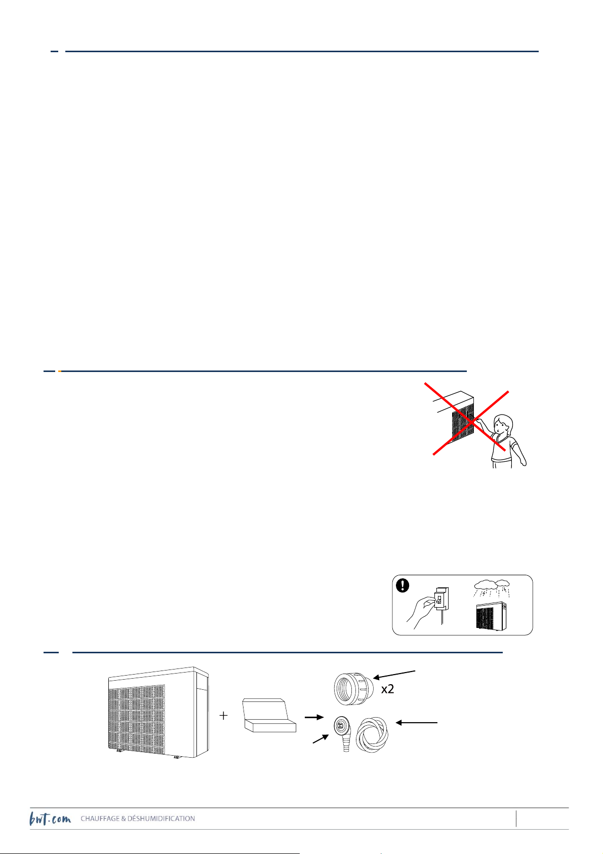
Never poke any object through the slots in the grating that protects the
impeller, this could damage the impeller.
Never operate the machine while the impeller’s protective grating is not
in position.
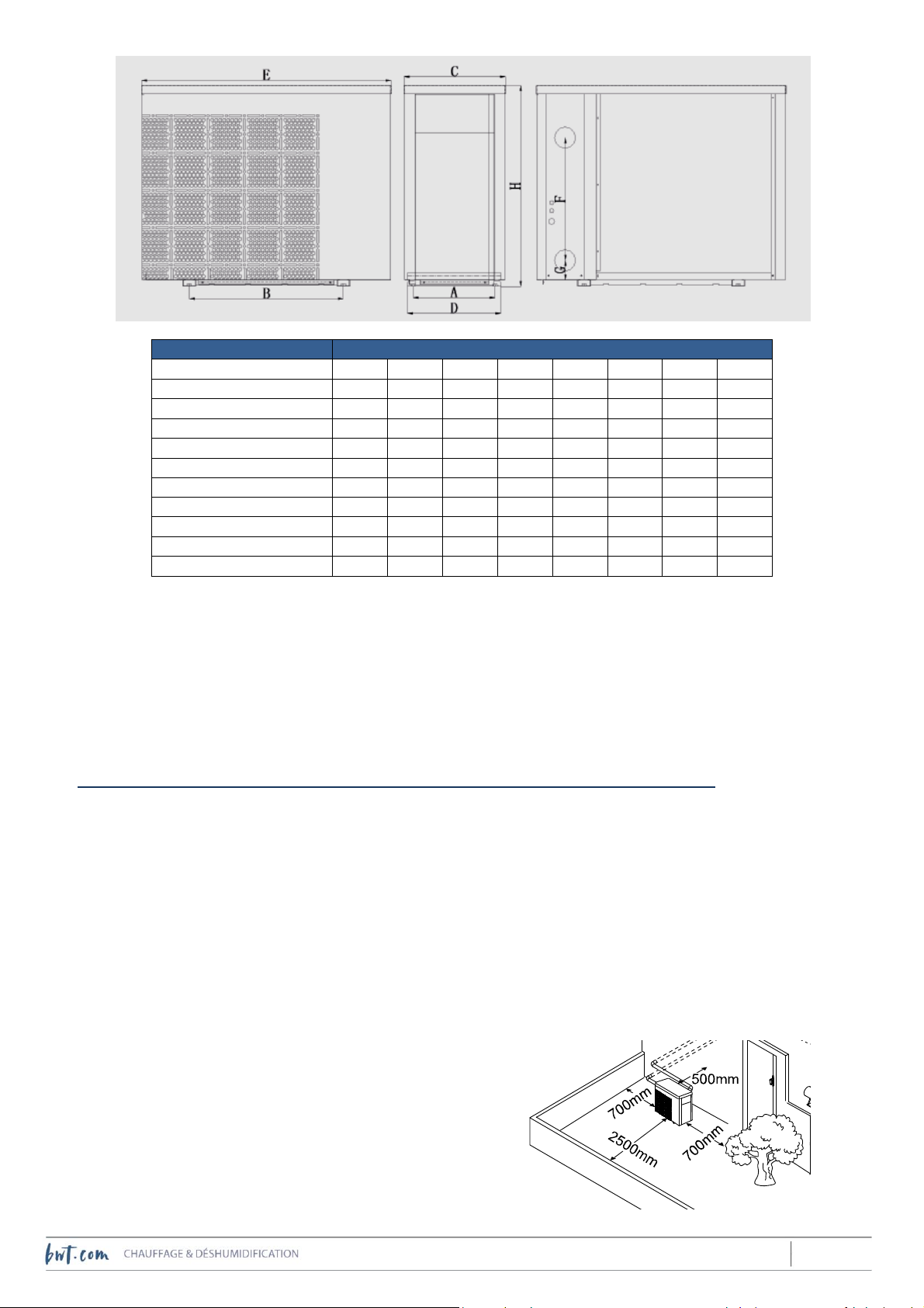
The distance separating the heat pump and its electrical panel from the water area should be determined
by a qualified professional in accordance with the regulations in effect in at the installation site - See the
recommendations set out in paragraph V.1 and V.3.
To avoid any risk of danger damaged power cables must be replaced immediately by the manufacturer, its
after sales service or similarly qualified personnel.
Always cut the power supply to the device upstream before any intervention requiring removal of the
panels or involving the hydraulic connections.
During storms, cut the power supply to the machine
When instne in; to dismantle the machine, proceed in the reverse
order.
III. Content
Caps for the hydraulic
unions
Condensate drain
union
Condensate drainage

6 / 18
2018/12 –B - Code : 33315
VI. Technical data and dimensions
Operating range: outdoor ambient air temperature between -7°C and +43°C.
Performance levels are maximised between +15°C and +25°C. The machine is not guaranteed to run properly
outside the -7°C / +43°C operating range.
Water resistance index for electrical parts : IPX4.
Set point temperature regulation range:
• Heating mode: 18°C to 35°C
• Cooling mode: 12°C to 30°C
Technical data
IPHCR
15
IPHCR
20
IPHCR
26
IPHCR
33
IPHCR
40
IPHCR
45
IPHCR
55
IPHCR
70
IPHCR
70T
IPHCR
100T
Advised water volume
(m3)
15~30
20~40
25~45
30~55
35~65
40~75
50~95
65~120
65~120
90~160
Power supply
230 V / 1 phase / ~ 50 Hz 60Hz
400 V / 3 ph /
~50 Hz 60Hz
max/min consumed
power(kW)*
1,06/
0,13
1,2/
0,17
1,5/
0,19
1,81/
0,23
2,2/
0,27
2,6/
0,30
3,18/
0,36
3,8/
0,55
3,9/
0,55
5,2/
0,61
max/min consumed
current (A)*
4,60/
0,56
5,2/
0,74
6,5/
0,83
7,87/
1,00
9,6/
1,17
11,3/
1,3
13,8/
1,57
16,5/
2,4
5,6/
0,79
7,4/
0,88
Maximum inlet
current(A)
6,5
8,0
9,0
11,5
12,0
13,0
17,0
20,0
7,0
9,5
Recommended flowrate
(m3/h)
2 to 4
2 to 4
3 to 4
4 to 6
5 to 7
6,5 to 8,5
8 to 10
10 to 12
10 to 12
12 to 18
Ext. Diam. of hydraulic
pipe
50 mm
Net weight kg
42
45
49
50
52
63
68
90
93
120
Dim (length x width x
height) mm
894 x 359 x 648
954 x 359 x 648
954x429
x 648
954x429
x 755
1084 x 429 x 948
1154 x
539 x 948
Sound power level dB(A)
at max / middle / min.
speeds**
61/
53,9/
51,6
62/
55,2/
52,6
63,7/
57,1/
52,4
64,5/
59,5/
55,9
68,8/
60,3/
55,1
67,6/
60,3/
56,9
69/
61,2/
55,7
69,7/
63,2/
58,3
69,7/
63,2/
58,3
69,5/
60,6/
57,4
Refrigerant mass
R 32 (grams)
550
650
750
800
950
1000
1200
2100
2100
2400
Standardised heating performance data according to the standard AFNOR AC-P 90-327 (ex DTP n°10): air temperature 15°C. water
temperature 26°C. relative humidity 70 %
Heating power at max
speed (kW)
4,8
6,3
7,3
8,7
10,5
11,5
14,0
18,0
18,0
24,5
COP at
max / 50 % / min speeds
4,5/6,3/
7,3
5,0/6,6/
7,4
4,8/6,8/
7,7
4,8/6,8/
7,7
4,6/6,6/
7,8
4,5/6,4/
7,8
4,4/6,3/
7,7
4,8/6,8/
8,1
4,8/6,8/
8,1
4,7/7,0/
8,0
Heating performance data. air temperature 26°C. water temperature 26°C. relative humidity 80 %
Heating power at max
speed (kW)
6,5
8,5
10,5
13,0
15,0
17,5
20,5
27,5
27,3
35,8
COP at
max / 50 % / min speeds
6,0/10,5
/14,7
7,4/10,9
/14,8
7,4/11,0
/15,0
7,3/11,0
/15,4
6,7/10,9
/15,5
6,2/11,1
/15,8
6,0/10,7
/15,3
6,5/11,2
/15,4
6,5/11,2
/15,3
5,8/10,9
/15,6
Cooling performance data. air temperature 35°C. water temperature 28°C. relative humidity 80 %
Cooling power (kW) at
max speed
3,0
4,0
4,6
5,6
6,8
7,8
10,0
12,2
12,2
16,5
*air 15°C, water 26°C **according to EN 12102 and EN ISO 3744

7 / 18
2018/12 –B - Code : 33315
Dimensions in mm
Model
A
B
C
D
E
F
G
H
IPHCR15
334
590
318
359
894
250
74
648
IPHCR20
334
590
318
359
894
250
74
648
IPHCR26
334
590
318
359
894
290
74
648
IPHCR33
334
590
318
359
954
280
74
648
IPHCR40
334
590
318
359
954
340
74
648
IPHCR45
404
590
388
429
954
390
74
648
IPHCR55
404
590
388
429
954
460
74
755
IPHCR70
404
720
388
429
1084
620
74
948
IPHCR70T
404
720
388
429
1084
620
74
948
IPHCR100T
514
790
498
539
1154
650
74
948
Nota bene: technical data and dimensions may be subject to modification, without notification, over time due to
product improvements. For more detail, refer to the information plate on the machine.
When the weather is cold and damp, frost can build up on the evaporator fins. This phenomenon is not the result of
a malfunction; the frost will be eliminated by automatic triggering of the thermodynamic defrosting cycle (inversion
of the refrigerant cycle). Once the frost has been melted, the machine will revert to normal operating mode.
The heat pump is fitted with a flow controller that only allows the machine to start up when the water flow rate
through the machine is adequate (see the recommended values in the technical data table).
V. Product installation
V.1) Siting
The following points must be taken into consideration:
The device must be installed outdoors
Condensate drainage
Connect the elbows and the condensate drainage hose to the hole in the machine floor such that the
condensates will be channeled to waste. Do not mix condensates with the pool water.
Distance from the water area
The distance must satisfy the stipulations of the local regulations if effect at the installation site. However,
this distance should not be so great that the length of the pipes makes it impossible to achieve the minimum
water flow rate necessary for correct operation of the
machine.
Clearance
The minimum recommended clearances between each
surface of the machine and the nearest obstacle (wall,
partition, hedge, etc.) are shown as indicated :
The machine should not be located in a corner where air
circulation and renewal could be hindered.

8 / 18
2018/12 –B - Code : 33315
Pay attention to the proximity of deciduous vegetation. Leaves, flowers, pollen, etc. could be drawn in by the
fans and obstruct the gratings.
Proximity to neighbours
Quite apart from the heat pump’s intrinsic acoustic level, (measured in a laboratory according to
standardized methods and on standardised installations) the installer is responsible for ensuring that the
installation site will not cause a phonic nuisance to neighbours, and take any necessary steps.
Refer to any local rules that apply.
Soil moisture
The heat pump must not be installed in a location where precipitation can accumulate and gather in
puddles around the machine.
Condensates generated by the heat pump while it is running must be drained away (use the drain
connection enclosed), and must not accumulate around the machine.
/30
Installation height
If the machine is wall mounted, the intrinsic strength of the wall and the mounting must be sized, with a
safety margin, to bear the weight of the machine when filled with water. Take exposure to prevailing winds
into consideration. Mounting brackets must be treated against corrosion. Piping must be attached to the
wall to be supported (but not by the machine).
Make sure the filtration pump can overcome the height difference between the filtration pump and the heat
pump. Take any necessary steps (increase pump power, additional pump, etc.).
V.2) Support
The heat pump must be attached by its feet to a solid, stable and horizontal base (stainless steel M
10 screws). A sloped position could interfere with the flow of condensates.
In the interest of noise abatement, the machine and pipes connected to it must be installed in such a way that
they do not vibrate while running.
V.3) Handling
Never lift the machine by its hydraulic unions.
Do not store the machine lying on its side. If the machine was laid on its side,
put it upright after storage,
and leave it stand like this, switched off, for at
least 48 hours.
V.4) Connection to the hydraulic circuit
The heat pump must be mounted on a
filtration circuit by-pass, downstream from
the sand filter, and upstream from the
injection of any treatment chemicals (the
titanium condenser is resistant to dilute pool
chemicals, but is not guaranteed against
exposure to high concentrations of pool
chemicals).
The bypass loop must be fitted with three
valves, one on the bypass intake, one on the
bypass outlet (isolation valves) and one

9 / 18
2018/12 –B - Code : 33315
between the two tapping points (valve to control the flow rate through the heat pump).
To limit heat loss from the pipes, bury them underground (at a depth of 50 to 80 cm depending on the
region) or lag the pipes. In any case, minimize the amount of uninsulated pipe exposed to the air.
V.5) Wiring
The machine must be wired in by a qualified professional, after the hydraulic connections have been
completed. When dismantling the machine, disconnect it electrically before disconnected the hydraulic
connections. The heat pump’s power cable connection terminal is located behind the socket. Use a cable with a wire
cross section that complies with the specification below, connected upstream to a breaking device rated
as set out in this table.
IPHCR
15
IPHCR
20
IPHCR
26
IPHCR
33
IPHCR
40
IPHCR
45
IPHCR
55
IPHCR
70
IPHCR
70T
IPHCR
100T
Thermal magnetic
circuit breaker rating (A)
8.0
10.0
11.0
14.0
15.0
16.0
21.0
24.0
9.0
12.0
bipolar
tetrapolar
Residual current device
sensitivity 30 mA max
bipolar
trtrapolar
Power cable (wire cross
section in mm2)
3 x 1,5
3 x 1,5
3 x 2,5
3 x 2,5
3 x 2,5
3 x 2,5
3 x 4,0
3 x 6,0
5 x 2,5
5 x 2,5
Remote installed control
panel cable (wire cross
section inmm2)
3 x 0.5
*For a cable length less than 10 m. Increase the wire cross section if the cable is more than 10 m long. The cable
length should never exceed 50 m.
! IMPORTANT :
Damaged cables must be replaced immediately by a qualified professional.
When installing the device, make sure earth wiring will present an ohmic resistance level complying with local
regulation requirements.
Check the electrical connections at the various terminals annually, tighten if necessary.
The heat pump’s electrical and electronic components are not guaranteed against overvoltages produced by
lightning strikes. The electrical supply in the home must be adequately protected against this risk.
①Unscrew the 2 screws from the base of the panel on
the right hand side and remove the bottom section
of the panel.
②Remove the 3 screws from the lid of the electrical
box.
③Connect the power cable according to the
standardised markings (NB: in 3ph installations, live wires
are marked R,S,T / in 1 ph installations, the live wire is
marked L).

10 / 18
2018/12 –B - Code : 33315
V.6) Heating priority :
It is possible to set the system up so that the heat pump will start up filtration outside programmed
filtration cycles if a heating demand is detected. This allows the pool water temperature to be held more
constantly around the set point.
In this case, the heat pump will start the filtration up every our (unless it is already running) to measure
the pool water temperature. If a heating demand is detected, it keeps the filtration pump running,
otherwise it stops the filtration pump after 3 minutes.
To do this, the electrical connections to be made will use the terminals marked P1 and P2 on the heat
pump terminal block:
Next, activate heating priority as follows on the control panel:
Press the and icons simultaneously for 5 seconds to access the parameter modification menu.
The “P0” parameter followed by “0” is displayed on the screen: “P0 0”.
Press to modify P0, then press to scroll until 1 is displayed : “P0 1”
Press once again to confirm,
Press to exit the parameter modification menu.
To leave the heating priority mode, set the P0 parameter back to 0following the above procedure.
! IMPORTANT : do not modify the value of parameters other than P0
VI. Start up and operation
After verifying that there is an adequate flow rate through the machine, press the
start (and stop) icon for 3 seconds to activate the screen, then press on to
start the heat pump. Where the machine detects the need to heat the water, in the
following 3 minutes, the fan sill start, followed by the compressor after about 30
seconds.
~ 230 V, 50 Hz 60 Hz
DDR 30 mA
Thermal magnetic circuit
breaker
Filtration pump
Switch
coil
Power
contacts
Thermal magnetic circuit breaker
~ 230 V (mono) ou 400 V
(tri) , 50 Hz 60 Hz
Filtration
timer
L
N
Earth
P1
P2
Heat pump

11 / 18
2018/12 –B - Code : 33315
Symbol
Designation
Function
ON/OFF
Power on/off
Lock-unlock /
Mode selection
Locking / unlocking the screen
Mode selection
Speed
Select Smart/Silence mode
Up / Down
Adjust set temperature
Notes :
Screen automatically locks after 30 s without any operation with it
When screen is locked :
a. the buttons are not displayed except the unlock one
b. when the heat pump is off, screen is dark and “0%” is displayed
VI.1) Screen lock/unlock :
- If screen is locked, press for 3 seconds to unlock it, buttons and icons are displayed
- If screen is unlocked, also press for 3 seconds to lock it, it shuts off ( still lit)
VI.2) Selecting the operating function :
There are three operating functions available (heating/ cooling /auto) :
If the auto function is active ( ), the machine will automatically go into heating or cooling mode
depending on the difference between the actual pool water temperature and the set point temperature: if
the water is colder than the set point temperature, heating mode will be activated, if the water is warmer
than the set point, cooling mode will be activated. Thus, the heat pump will automatically keep the water
temperature at the set point value.
Water temperature
at the inlet
Cooling indicator
Auto mode icon
Heating indicator
Current power, in %
of max. power
Compressor running
Water temperature
at the outlet
Smart/Silence mode
Water at the inlet
Water at the oulet

12 / 18
2018/12 –B - Code : 33315
When this function is active, the set temperature can be fixed between 12 and 35°C.
The heating function only enables to increase the water temperature. If the water temperature
overpasses the set value due to the ambiant conditions, the heatpump keeps off, and will not cool the water.
Thus, this function is to be activated only when the pool water temperature is likely to decrease
spontaneously.
When this function is active, the set temperature can be chosen between 18 and 35°C.
The cooling function only enables to decrease the water temperature. If the water temperature falls
under the set value due to the ambiant conditions, the heatpump keeps off, and will not heat the water.
Thus, this function is to be activated only when the pool water temperature is likely to increase
spontaneously.
When this function is active, the set temperature can be chosen between 18 and 30°C.
The indicator showing the active function is displayed left in the upper part of the screen when unlocked. To modify
it, press once or several times until the icon of the expected function is displayed.
Note : the function ultimately selected by the operator will be active when restarting the heat pump after being off.
VI.3) Selecting the set temperature value :
Screen being unlocked, press or to display the set temperature, and then to change its value with these
same arrows.
VI.4) Selecting the operating mode :
The heat pump has 2 operating modes, each has its own specific advantages:
When the heat pump is started up (by pressing the On/ Off button), it enters SMART mode by default (the
corresponding icon is displayed on the screen)
Press the key to switch to SILENCE mode (the corresponding icon is displayed on the screen)
To revert to SMART mode, press the key again.
Pressing this key will toggle between the two operating modes.
VI.5) Defrosting (heating and auto functions only)
The heat pump is designed such as it automatically detects when a defrosting cycle is needed. In such a case, the
defrosting cycle starts, and stops automatically.
Mode
Recommandation
Caractéristiques
Smart
Standard operating
mode, used to raise
the pool water
temperature to the set
point
Heating power is modulated between
25% and 100%, to heat or cool the
water rapidly if a high power demand is
detected
Silence
Proximity of
neighbourg
Heating power is modulated between
25% and 80%, the machine’s noise
emission sound output is reduced 3dB
(A) compared to operation at 100%
power

13 / 18
2018/12 –B - Code : 33315
When the heat pump is busy heating the water, the operator can also starts a defrosting cycle manually if it appears
suitable (for example, where a high amount of frost has not been totally eliminated by the defrosting cycle). For this,
press and simultaneously for 5 seconds.
flashes during a defrosting cycle.
Note : do not start a manual defrosting cycle if :
- Compressor has not been running continuously for at least 10 minutes
- Less than 30 minutes after a defrosting cycle has stopped.
VII. Upkeep and maintenance
Check the evaporator fins regularly for debris (leaves, flowers, pollen, etc.), clean the fins with a soft brush and soapy
water or with ordinary detergents. Do not use solvants. Check the condensate drainage tubes for obstructions
(water flowing around the machine). The machine cabinet may be cleaned with soapy water or ordinary detergent.
Do not use solvants.
VII.1) Shut down for winterizing :
If filtration is shut down to winterize the pool, or if the water is not heated during active winterization:
• Cut electrical power to the machine (thermal magnetic circuit breaker set to off).
• Close the 2 isolation valves on the heat pump bypass loop.
• Unscrew the 2 hydraulic unions to drain all water from the machine, and then cover these with the
caps provided (to avoid any unwanted guests taking up residence over the winter period).
• Cover the machine, if possible, to prevent dirt from building up on the external parts.
VII.2) –Technical inspections :
The installation should be inspected once a year by a technician qualified to handle refrigerants.
Check that electrical and hydraulic connections are correctly tightened.
Depending on the mass of refrigerant inside the machine, regulations may require that the refrigerant circuit be
regularly inspected for leaks. Refer to the local regulation on that topic. The inspection certificate must be kept.
VII.3) –Spare parts :
Spare parts specific to Fairland heat pumps, and essential for them to run correctly, will be available for at least 5
years after the date of purchase of the machine (minimum duration in the event that the product is withdrawn from
the market).
VIII. Error messages
Some errors do not cause the compressor to stop, but are displayed on screen (some will also generate an aural
alarm) for 3 minutes every 30 minutes until either the problem is resolved, or the machine is stopped using the On/
Off button.
Other more critical errors will stop the compressor. The power supply to the machine must be disconnected before
proceeding with the repair. Upon restarting the machine, the error is reset and only reappears if the problem has
not been resolved. Error messages associated with abnormal operating conditions are shown in bold in the following
table.

14 / 18
2018/12 –B - Code : 33315
IX. Trouble shooting
NO.
Displayed code
Not Fault description
1
E3
No water protection
2
E5
Power supply excesses operation range
3
E6
Excessive temp difference between inlet and outlet water(Insufficient water flow protection)
4
Eb
Ambient temperature too high or too low protection
5
Ed
Anti-freezing reminder
NO.
Displayed code
Fault description
1
E1
High pressure protection
2
E2
Low pressure protection
3
E4
3 phase sequence protection (three phase only)
4
E7
Water outlet temp too high or too low protection
5
E8
High exhaust temp protection
6
EA
Evaporator overheat protection (only at cooling mode)
7
P0
Controller communication failure
8
P1
Water inlet temp sensor failure
9
P2
Water outlet temp sensor failure
10
P3
Gas exhaust temp sensor failure
11
P4
Evaporator coil pipe temp sensor failure
12
P5
Gas return temp sensor failure
13
P6
Cooling coil pipe temp sensor failure
14
P7
Ambient temp sensor failure
15
P8
Cooling plate sensor failure
16
P9
Current sensor failure
17
PA
Restart memory failure
18
F1
Compressor drive module failure
19
F2
PFC module failure
20
F3
Compressor start failure
21
F4
Compressor running failure
22
F5
Inverter board over current protection
23
F6
Inverter board overheat protection
24
F7
Current protection
25
F8
Cooling plate overheat protection
26
F9
Fan motor failure
27
Fb
Power filter plate No-power protection
28
FA
PFC module over current protection

15 / 18
2018/12 –B - Code : 33315
The following table describes situations that may seem abnormal although no error code is displayed on the
machine. For any other problems, please contact the seller.
Problem
Possibles causes
Possible solutions
The heat pump will
not
start
No power supply
Check that no circuit breakers are
tripped
Check that the electrical connections
are not loose.
The machine is off
Press the On/ Off button.
The temperature set point
has
been over shot
Check the set point temperature,
compare this with the water temperature at the
inlet.
The heat pump is
running, but the pool
water temperature is
not changing
Heat loss is too high
Make sure that the pool is covered with
an isothermal cover while it is not in
use.
Make sure that pipes connecting the
heat pump to the pool are buried at the
correct depth, or are correctly lagged.
In the case of above-ground pools,
check that the heat loss from the pool
walls is not too high.
The daily run time is too
short
given the coolness of
ambient air
Inadequate programming of the timer
that controls filtration start and stop:
- Length of the filtration cycel too short
- Filtration only at night when the
ambient T°C is particularly low
The ambient air
temperature is
exceptionally low
Wait until the temperature returns to
normal levels.
Check that the machine is correctly
sized for the water volume and period
of use.
Air is not circulating freely
Check that the evaporator fins are
clean.
Check that the installation instructions
set out in paragraph IV.1 have been
respected
The heat pump trips
the
magnetic thermal
circuit
breaker is an
untimely
manner
Circuit breaker incorrectly
set
Check that it is set in accordance with
recommendations set out in paragraph
IV.3
Electrical short circuit
Have the heat pump electrical wiring
and its power supply checked by a
qualified electrician.
Circuit breaker common to
several devices and under
sized
Install a circuit breaker specific to
the hat pump in accordance with the
recommendations set out in paragraph
IV.3
The heat pump trips
the RCD
Earth leakage current
Have the heat pump electrical wiring
and its power supply checked by a
qualified electrician.

16 / 18
2018/12 –B - Code : 33315
NOTES

17 / 18
2018/12 –B - Code : 33315

18 / 18
2018/12 –B - Code : 33315
Version : B18Ir32
This manual suits for next models
9
Table of contents
Other BWT Inverter manuals
Popular Inverter manuals by other brands

SMA
SMA SUNNY MINI CENTRAL 6000TL installation guide

SunSynk
SunSynk SUNSYNK-3.6K-SG01/03LP1 Installer manual

Power One
Power One AURORA PVI-6000-OUT-US-W Installation and operation manual

Deye
Deye SUN-30K-G04 user manual

Winco
Winco DR2014 Installation and operator's manual

Hitachi
Hitachi HFC-VWA2 SERIES instruction manual