BYOC Scrambled Octave User manual

1
Build Your Own Clone
Scrambled Octave
Kit Instructions
Warranty:
BYOC, LLC guarantees that your kit will be complete and that all parts and
components will arrive as described, functioning and free of defect. Soldering,
clipping, cutting, stripping, or using any of the components in any way voids this
guarantee. BYOC, LLC guarantees that the instructions for your kit will be free of
any majors errors that would cause you to permanently damage any components
in your kit, but does not guarantee that the instructions will be free of typos or
minor errors. BYOC, LLC does not warranty the completed pedal as a whole
functioning unit nor do we warranty any of the individual parts once they have
been used. If you have a component that is used, but feel it was defective prior to
you using it, we reserve the right to determine whether or not the component was
faulty upon arrival. Please direct all warranty issues to:
Return:
BYOC, LLC accepts returns and exchanges on all products for any reason, as long as
they are unused. We do not accept partial kit returns. Returns and exchanges are for the
full purchase price less the cost of shipping and/or any promotional pricing. Return
shipping is the customer’s responsibility. This responsibility not only includes the cost of
shipping, but accountability of deliver as well. Please contact

2
Tech Support:
BYOC, LLC makes no promises or guarantees that you will successfully complete your
kit in a satisfactory manner. Nor does BYOC, LLC promise or guarantee that you will
receive any technical support. Purchasing a product from BYOC, LLC does not entitle
you to any amount of technical support. BYOC, LLC does not promise or guarantee that
any technical support you may receive will be able to resolve any or all issues you may
be experiencing.
That being said, we will do our best to help you as much as we can. Our philosophy at
BYOC is that we will help you only as much as you are willing to help yourself. We
have a wonderful and friendly DIY discussion forum with an entire section devoted to the
technical support and modifications of BYOC kits.
www.buildyourownclone.com/board
When posting a tech support thread on the BYOC forum, please post it in the correct
lounge, and please title your thread appropriately. If everyone titles their threads
“HELP!”, then it makes it impossible for the people who are helping you to keep track of
your progress. A very brief description of your specific problem will do. It will also
make it easier to see if someone else is having or has had the same problem as you. The
question you are about to ask may already be answered. Here are a list of things that you
should include in the body of your tech support thread:
1. A detailed explanation of what the problem is. (not just, “It doesn’t work, help”)
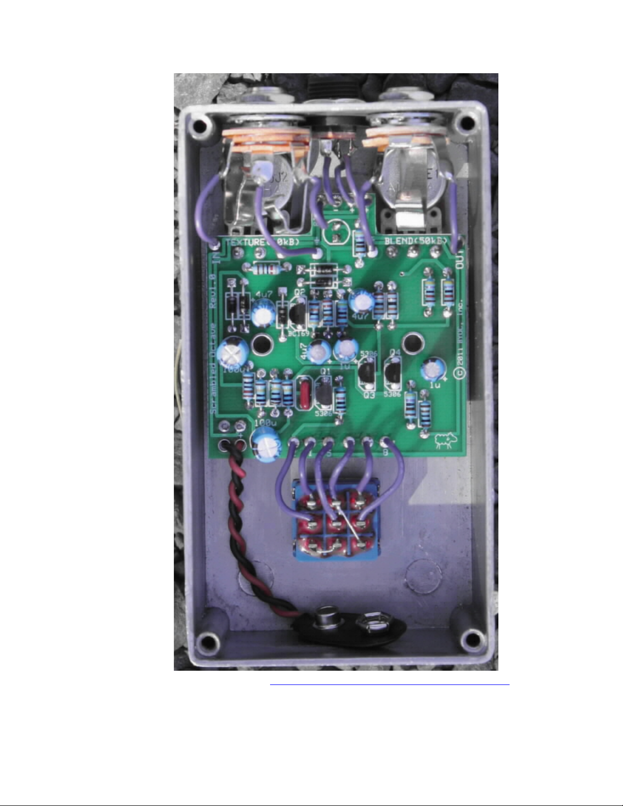
2. Pic of the top side of your PCB.
3. Pic of the underside of your PCB.
4. Pic that clearly shows your footswitch/jack wiring and the wires going to the PCB
5. A pic that clearly shows your wiring going from the PCB to the pots and any other
switches(only if your kit has non-PC mounted pots and switches)
6. Is bypass working?
7. Does the LED come on?
8. If you answer yes to 6 and 7, what does the pedal do when it is "on"?
9. Battery or adapter.(if battery, is it good? If adapter, what type?)
Also, please only post pics that are in focus. You're only wasting both parties' time if you
post out of focus, low-res pics from your cell phone.
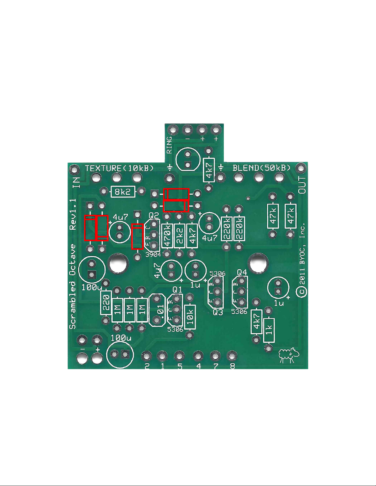
Revision Notes:
Rev 1.0 There are no known errors.
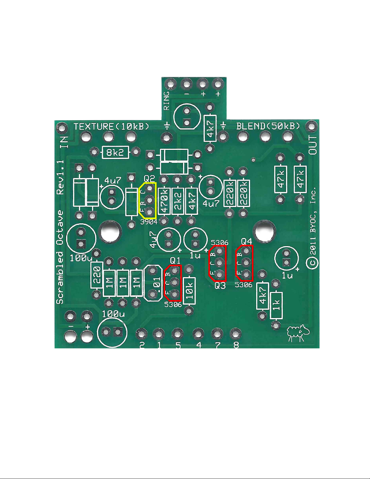
Rev 1.1 Changed Q2 to 2N3904
Copyrights:
All material in this document is copyrighted 2018 by BYOC, LLC

3
SCRAMBLED OCTAVE KIT
INSTRUCTION INDEX
Parts Checklist……………………..............…….....page 4 - 5
Populating the Circuit Board…………...................page 6 - 13
Main PCB Assembly…….........................................page 14 - 17
Wiring........................................................................page 18 - 21
Operation Overview.................................................page 22
Schematic...................................................................page 23

4
Parts Checklist for BYOC Scrambled Octave Kit
Resistors:
1 - 220ohm (red/red/black/black/brown)
1 - 1k (brown/black/black/brown/brown)
1 - 2k2 (red/red/black/brown/brown)
3 - 4k7 (yellow/purple/black/brown/brown)
1 - 8k2 (gray/red/black/brown/brown)
1 - 10k (brown/black/black/red/brown)
2 - 47k (yellow/purple/black/red/brown)
2 - 220k (red/red/black/orange/brown)
1 - 470k (yellow/purple/black/orange/brown)
3 - 1M (brown/black/black/yellow/brown)
Capacitors:
1 - 10n or .01µfilm (may say ‘103’ on the body)
2 - 1µaluminum electrolytic
3 - 4.7µf aluminum electrolytic
2 - 100µf aluminum electrolytic
Diodes:
5 - 1N456 (small black plastic with a silver or white stripe)
Transistors:
1 - 2N3904
3 - 2N5306
Potentiometers: Be sure to snap off the small tab on the side of each panel mounted
pot.
1 - B10k linear (TEXTURE)
1 - B50k audio (BLEND)

5
Hardware:
1 - drilled enclosure w/ 4 screws
1 - byoc classic Scrambled Octave PCB
1 - 3PDT footswitch
2 - knobs
2 - Lock Washers
1 - AC adaptor jack
1 - ¼”mono jack
1 - ¼”stereo jack
1 - red LED
1 - battery snap
4 - bumpers
hook-up wire

6
for a larger pic, go to www.buildyourownclone.com/scramblerguts.pdf

7
Populating the Circuit Board
STEP 1: Add the diodes. Be sure to match the end of the diode with the stripe to the
layout on the PCB. The stripped end should go in the square solder pad.

8
STEP 2: Add the resistors. Resistors are not polarized, so it does not matter which end
goes in which solder pad. Take your time and be sure not to confuse similarly banded
resistors such as the 470k with the 4k7 or the 220k with the 220 ohm. If you have
difficulty reading the color bands, use a digital multimeter to test the value of each
resistor.

9
Step 3: Add the film capacitor. These are not polarized and can be inserted into the PCB
either way.

10
Step 4: Add the Transistors. Be sure to orient the transistosr so that the flat side of the
tansistor body matches up with the flat side on the PCB layout. Make sure to insert the
2N3904 transistor into the Q2 space highlighted in yellow.

11
STEP 5: Add the aluminum electrolytic capacitors. These are polarized. The positive
end will have a longer lead and should go in the square solder pad. The negative end will
have a shorter lead with a black or white stripe running down the body of the capacitor.

12
Step 6: Add the battery snap. Thread the solder ends of the battery snap into the strain
relief holes from the bottom solderside of the PCB and out through the top. Insert the
solder ends of the battery snap wires into the topside of their respective solder pads.
Solder on the bottom side of the PCB. Remember the red wire goes in the “+” hole and
the black wire goes in the “-” hole.

13
Step 7: Add wires to the IN, OUT, RING, and two Ground eyelets. Start by cutting four
2.5” pieces of wire and one 1.5” piece of wire. Strip 1/4” off each end and tin the ends.
Tinning means to apply some solder to the stripped ends of the wires. This keeps the
strands from fraying and primes the wire for soldering. Solder a 2.5” piece of wire to
each of the IN, OUT, and Ground eyelets on the PCB. Solder the 1.5” piece of wire to
the RING eyelet on the PCB. Load the wires in from the top and solder on the bottom of
the PCB.

14
Main PCB Assembly
Below is a picture of an “internal nut” DC adapter jack with nylon nut. Your kit may
come with a jack that looks like this, or it may come with an “external nut” jack with
metal nut. Both have the exact same termination and both function identically. Internal
nut jacks mount to the enclosure from the outside and the nut goes on the inside.
External nut jacks mount from the inside and the nut goes on the outside.
Step 1: Mount the DC adapter jack to the enclosure.
The sleeve disconnect terminal of the DC adapter jack connects directly to the positive
terminal of the battery via the PCB. The sleeve disconnect terminal is connected to the
sleeve terminal when there is no DC adapter plugged into the jack. When a DC adapter
jack is plugged into the DC adapter jack, the connection between the sleeve disconnect
terminal and the sleeve terminal is broken, thus disconnecting the batter from the circuit
when a DC power supply is in use. This allows you to safely keep a battery in your pedal
and still use a DC power supply.

15
Step 2: Connect the TIP (negative) terminal of the DC adapter jack to the “-” eyelet on
the PCB with 2 inches of hook up wire. Connect the SLEEVE of the DC adaptor jack to
the “+” eyelet on the far right side of the PCB with 2 inches of hook up wire. Connect
the battery disconnect terminal of the DC adaptor jack to the “+” eyelet more towards the
center of the PCB with 2” of hookup wire. Load the wires in from the bottom of the PCB
and solder on the topside.

16
Step 3: Flip the PCB over so that the bottom or solder side is up. Insert the
B10k(TEXTURE), B50k(BLEND) potentiometers, and the LED into the bottom side of
the PCB. DO NOT SOLDER ANYTHING YET!!! The LED will have one lead that is
longer than the other. The longer lead goes in the hole with the square solder pad.
Step 4: Hold the PCB in one hand so that the component side of the PCB is in the palm

17
of your hand and the bottom side with the pots, toggle switch and LED is facing up. Now
use your other hand to guide the predrilled enclosure onto the PCB assembly so that the
pots and LED all go into their respective holes. Once the PCB assembly is in place,
secure it by screwing on the washers and nuts for the pots and toggle switch. Only
tighten them with your fingers. You do not want them very tight yet. Be sure to keep
your hand on the PCB so that it does not fall off the PC mounting posts of the pots and
toggle switch.
Step 5: Turn the entire pedal over so that the component side of the PCB if facing up.
Lift the PCB up off the pots and toggle switch about 2mm just to make sure that the back
of the PCB does not short out against that pots. Make sure the PCB is level and
symmetrically seated inside the enclosure.
Step 6: Solder the pots and LEDs. You will solder these parts on the component side of
the PCB. After you have soldered them in place, be sure to tighten up their nuts.

18
Wiring
Step 1: Install the 1/4” jacks to the enclosure.

19
Step 2: Install the footswitch. Orient the footswitch so that the flat sides of the solder
lugs are like the diagram below. NOTE: There are no actual number markings on the
footswitch. There are two correct ways you can orient the footswitch. They are both 180
degrees of each other. Either way is fine. It does not matter as long as the flat sides of
the solder lugs are running horizontal, not vertical.

20
Step 3: Connect the pre stripped and tinned wires to the 1/4” jacks.
Step 4:
Cut 4 x 3/4” pieces of wire. Strip 1/8” off each end. These will be used to connect
lugs/eyelets 1, 2, 7, & 8
Cut 1 x 1” piece of wire. Strip 1/8” off each end. This will be used to connect lug/eyelet
5
Cut 1 x 1.5” peice of wire. Strip 1/8” of one end. Strip 1/2” off the other end. This will
Table of contents
Other BYOC Music Pedal manuals

BYOC
BYOC Phaser User manual

BYOC
BYOC Silver Pony Manual

BYOC
BYOC Bass Overdrive User manual

BYOC
BYOC 250+ User manual

BYOC
BYOC Stereo Analog Flanger User manual

BYOC
BYOC Large Beaver Triangle User manual

BYOC
BYOC E.S.V. Fuzz User manual

BYOC
BYOC Classic Delay User manual

BYOC
BYOC Analog Chorus Manual

BYOC
BYOC BA6110 User manual

BYOC
BYOC Armstrong Twin User manual

BYOC
BYOC Shredder User manual

BYOC
BYOC Large Beaver NYC User manual

BYOC
BYOC Analog Vibrato Manual

BYOC
BYOC Full Circle Bass Fuzz Manual

BYOC
BYOC Amp Selector and Stereo FX Router User manual

BYOC
BYOC Chancellor Overdrive User manual

BYOC
BYOC Parametric EQ User manual

BYOC
BYOC Li'l Pony User manual

BYOC
BYOC Classic Fuzz User manual