manuals.online logo
Brands
  1. Home
  2. •
  3. Brands
  4. •
  5. Byron
  6. •
  7. Accessories
  8. •
  9. Byron TX-414 User manual

Byron TX-414 User manual

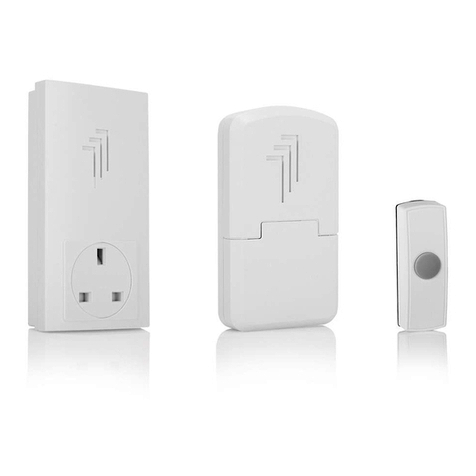
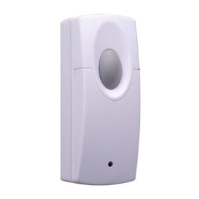
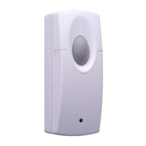
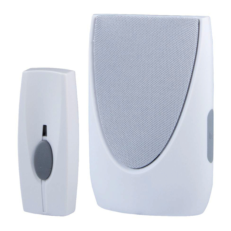
The Wire Free Door Chime Kit consists of three separate units:
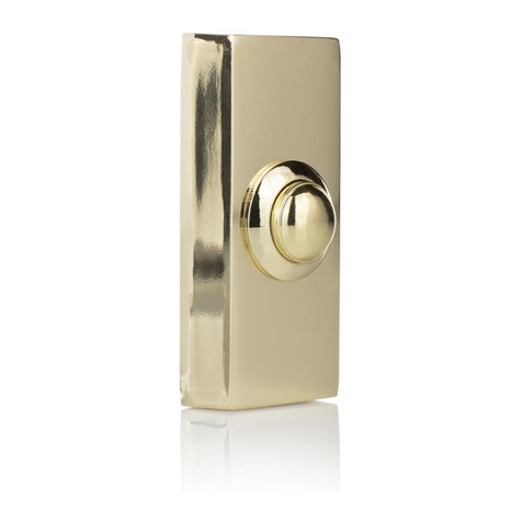
1.Wired Brass Push Button unit
2. Converter (Transmitter)
3. Plug-In Door Chime unit (Receiver)
When the Converter is activated, it sends a wirefree
signal to the door chime.As the operating range is up
to 100 metres (320 ft. approx.), you can Plug the door
chime into any convenient wall socket virtually anywhere
in the home.
However, the transmission range of the wirefree signal
will be reduced if the signal is transmitted through a
number of walls or ceilings. Metal, and UPVC
doorframes will also reduce the operating range.
Battery Installation
Wire Free Converter
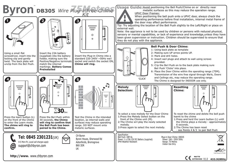
1.The Converter unit is operated by 1 x 12 volt battery
(A23 - included).
2. Remove the back of the case by pushing in the tab on the
bottom with a small, flat screwdriver.
3. Insert 1 x 12 volt battery (A23 - included) in the battery
compartment, ensuring the battery polarity match the internal
markings.
4. Snap the front cover of Converter back on, then it is ready to use.
Plug-In Door Chime unit
1. Door chime unit is powered by A/C mains power (230volt ~ 50Hz)
2. Simply plug the Door Chime Unit into any convenient wall socket, the
operation indicator (Green LED) will light up, then it is ready to use.
3.Test to ensure the Door Chime unit is located within the operation range
before final installation.
SoundVolume Adjustment
Tone sound volume control can be adjusted to high or low, the high-low
switch is located at the side of the door chime unit.
2.Then use the second hole located at the bottom half of the Converter as a template,
mark the fixing position for the unit.Drill hole and fit wall plug and secure the Converter
unit with the screw (self-tapping N3 x 16mm screw) in position.
3. Alternatively, use the double-sided self-adhesive pad (included) to attach the Converter
to the fixing position between the bell push and door chime unit.
c) Door Chime unit: Plug the Door Chime Unit into any convenient wall socket, the operation
indicator (Green LED) will light up, then it is ready to use.
Installation Guide
a)Wired Bell Push: Using the two holes of the back of push button as a
template, mark the fixing position for the unit. Drill hole and fit wall plug and
secure the Push Button Unit with screws (self-tapping N3 x 16mm screw) in
position outside your front door or the position nearby.
b) Converter (Position inside door) :
1. Drill holes and fit wall plug (if fixing to masonry) and screws (self-tapping N3 x 16mm
screw) to fixing position.Leave a gap of 3mm between the screw head and the wall.
Locate the keyhole slot on the back of the unit over the screw.
Important: Mounting the Converter unit on the UPVC doorframes or metal surface will
reduce the broadcasting range seriously.
Tone Selection
The tone selector is located inside the Converter unit. It is a small jumper switch on the top
right corner of battery compartment marked with “T”.When a jumper switch is removed onto
the 2 pins on the left, the tone will change from “Westminster” tone to “Ding-Dong”.
The converter unit is pre-set to “Westminster” therefore, if no change is required, it should not
be adjusted.
Westminster Ding-Dong
Digital Code Set Up
The unit comes from the factory on a pre-set radio frequency digital code.However, should
your door chime activate intermittently for no reason at all, it is possible that a similar unit is
operating nearby on the same frequency digital codes.The encoded frequency of the
Converter (transmitter) and Door Chime (receiver) can be changed to avoid this problem.
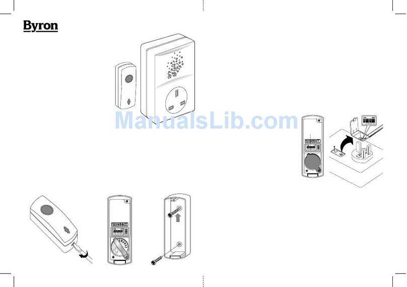
1. Converter: Remove the back of the case by pushing in the tab on
the bottom with a small, flat screwdriver.
Door Chime Unit: Firstly, unplug the unit from wall socket.
Unlock the locking screw and slide open the digital code setting
compartment on the back of the Chime Unit.
2.There is 6 position dip switch marked 1,2,3,4,5 & 6. Use an
insulated tool to alter the dip switch levers to the “On” or “Off”
position, which can be altered to achieve a total of sixty-four
(64) possible digital codes.
3. Select any combination ensuring it is set to the same code on
both converter and door chime units.E.g. If the 1 & 2
dipswitches are down in your converter, then the 1 & 2
dipswitches must be down in your chime unit.
4.Test to ensure correct operation before final installation.
Important
1. Do not mount the Converter unit onto any metal or UPVC doorframes, as this will reduce
the operating range.
2. Do not immerse either unit in water.
3. Do not mount either unit close to fireplace or expose to high temperature.
4. Do not use different type of batteries, or mix up old and new batteries.
5. Do not leave exhausted batteries in either unit. If leaving the doorbell for long period,
remove the battery from compartments to prevent leakage.
6. Always use alkaline batteries as these will give longer service and less likely to leak.
7.The Converter and Door Chime unit are designed for indoor use only.
8. Please dispose of old, defective batteries in an environmentally friendly manner in
accordance with the relevant legislation.
9. Make sure that no naked flame sources, such as lighted candles, should be placed on the
unit.
10.The unit should not be exposed to dripping or splashing and that no objects filled with
liquids, such as vases, shall be placed on the unit.
11. CAUTION: Replace only with the same or equivalent type of battery that are
recommended by the manufacturer.
12. CAUTION: Danger of explosion if battery is incorrectly installed or replaced.
Please note that these diagrams are only for reference as a guide.
EACH Wired chime can be wired differently, so if you encounter problems,
PLEASE CALLTHE HELPLINE NO. 0121 5449499
Wiring Installation
The Converter is designed to change your new Brass Wired Bell Push to wirefree.
1. Simply connect your Wired Bell Push with the cable from Converter to the terminals on your
bell push.
2.Your Wired Bell Push with Converter is ready to use. In case a Transformer (A/C 8V) is used
to power the Wired Bell Push and Wired Door Chime.
1. Remove the back of the case by pushing in the tab
on the bottom with a small, flat screwdriver.
2. Disconnect the wire that is connected with the
Wired Door Chime.
3. Feed the wire via the hole on the back of the
Converter, connect the wire to the terminal positions
marked in diagrams below.
4. Snap the front cover of converter back on, then it is
ready to use.
Important: Do not connect the Converter unit with
any Lighted Bell Push.
Problem
Chime does not
sound but LED
lights on
Converter
Possible Causes
1. Units are out of range
(max. range 100m)
2. Converter and Chime units are
not on the same digital code
3. Converter not wired correctly
Suggested Remedy
1. Operate the Chime unit within
the operation range (100m)
2. Re-set the digital code
(see Digital Code Set Up)
3. See wiring diagrams opposite
Chime does not
sound plus no
lights on Push
Converter LED
1. Flat Converter battery
2.Wrong polarity of battery in
Converter
1. Change the battery
2. Re-insert battery as internal
marking in right polarity
Chime sounds
without Converter
being pressed
A similar Wire Free Door Chime
product is operating nearby on the
same frequency digital code
Re-set the digital code
(see Digital Code Set Up)
Trouble Shooting & User Hints
NOTE: There are no serviceable parts in the unit, do not attempt to repair it.
Specification
A. Converter unit
Power
Consumption : 1 x 12 volt battery (included, replace with Byron model SD-100)
: 3.0mA - ON
0.003mA - OFF
B. Door Chime unit
Power
Operating Temperature
Operating Distance
Selectable Tone
Selectable Digital Code
: A/C mains power (230 volt ~ 50Hz)
: -10°C to +40°C
: 100 metres (320 feet approx.) in open field
:“Westminster” & “Ding-Dong”
:Total sixty-four (64) possible digital codes
Wire Free Plug-In Door Chime Kit with Converter-TX-414
Wired Bell
Push
Converter unit
B+C SWITCH
TX
Chime
unit
WIRED
CHIME
(Transformer
operation)
3
T
Converter
unit
A and C
TX
Chime
unit
WIRED
CHIME
(Transformer
operation)
4
T
Converter
unit
A and C
TX
Chime
unit
WIRED
CHIME
(Battery
operation)
2
Converter
unit
A and C
TX
Chime
unit
1
Converter
unit
B and C

Other Byron Accessories manuals

Byron DB302 Owner's manual

Byron

Byron DB302 Owner's manual

Byron B314 Owner's manual

Byron

Byron B314 Owner's manual

Byron BY301 Owner's manual

Byron

Byron BY301 Owner's manual

Byron SX-212i Owner's manual

Byron

Byron SX-212i Owner's manual

Byron SX-15i Owner's manual

Byron

Byron SX-15i Owner's manual

Byron SX-20 Owner's manual

Byron

Byron SX-20 Owner's manual

Byron BY112 Owner's manual

Byron

Byron BY112 Owner's manual

Byron SX-6 Owner's manual

Byron

Byron SX-6 Owner's manual

Byron SX-34 User manual

Byron

Byron SX-34 User manual

Byron DB306 Owner's manual

Byron

Byron DB306 Owner's manual

Byron BY32 User manual

Byron

Byron BY32 User manual

Byron Home Easy HE-304 User manual

Byron

Byron Home Easy HE-304 User manual

Byron DB305 Owner's manual

Byron

Byron DB305 Owner's manual

Byron Victoria Bell User manual

Byron

Byron Victoria Bell User manual

Byron Home Easy HE-306 User manual

Byron

Byron Home Easy HE-306 User manual

Byron SX-201I User manual

Byron

Byron SX-201I User manual

Byron DIC-24815 User manual

Byron

Byron DIC-24815 User manual

Byron DB303 Owner's manual

Byron

Byron DB303 Owner's manual

Byron SX210i Owner's manual

Byron

Byron SX210i Owner's manual

Byron BY201 Owner's manual

Byron

Byron BY201 Owner's manual

Byron SX-15i User manual

Byron

Byron SX-15i User manual

Byron W-251i Owner's manual

Byron

Byron W-251i Owner's manual

Byron SX-120 Owner's manual

Byron

Byron SX-120 Owner's manual

Byron BY212 Owner's manual

Byron

Byron BY212 Owner's manual

Popular Accessories manuals by other brands

ELCOM TLM 1500 User manual & maintenance guide

ELCOM

ELCOM TLM 1500 User manual & maintenance guide

Emos RL3921 manual

Emos

Emos RL3921 manual

Sewha SI 300 instruction manual

Sewha

Sewha SI 300 instruction manual

Decora LEVITON ODS0D-IDW installation instructions

Decora

Decora LEVITON ODS0D-IDW installation instructions

Lippert Components Solera Slide Topper Installation and owner's manual

Lippert Components

Lippert Components Solera Slide Topper Installation and owner's manual

Snom M900 Provisioning guide

Snom

Snom M900 Provisioning guide

TIS MS-PIR-M installation manual

TIS

TIS MS-PIR-M installation manual

ipf DW34311 Series manual

ipf

ipf DW34311 Series manual

Astro Shop GSTAR-EX Quick reference guide

Astro Shop

Astro Shop GSTAR-EX Quick reference guide

Bosch Rexroth 3 842 547 200 Assembly instructions

Bosch

Bosch Rexroth 3 842 547 200 Assembly instructions

SELT ITALIA installation manual

SELT

SELT ITALIA installation manual

Medisana 60230 instruction manual

Medisana

Medisana 60230 instruction manual

Furuno Precision PG-500 Specifications

Furuno

Furuno Precision PG-500 Specifications

Carel EW00S 00 Series manual

Carel

Carel EW00S 00 Series manual

Kele KCO-NO2 user manual

Kele

Kele KCO-NO2 user manual

A&D AD-4329A instruction manual

A&D

A&D AD-4329A instruction manual

TWINBIRD SC-UE15 Operation manual

TWINBIRD

TWINBIRD SC-UE15 Operation manual

Omron E3NT-L brochure

Omron

Omron E3NT-L brochure

manuals.online logo
manuals.online logoBrands
  • About & Mission
  • Contact us
  • Privacy Policy
  • Terms and Conditions

Copyright 2025 Manuals.Online. All Rights Reserved.