BZB Gear BG-BPTZ-3XU User manual

BG-BPTZ-3XU
BG-BPTZ-10XU
HD Color Video Camera
User Manual

1
Warnings
Electrical Safety
Installation and operation must conform with local electric safety standards.
Use care when moving
Avoid stress, vibration and moisture in transportation, storage and installation.
Polarity of power supply
The power supply of the product is ±12V, the max electrical current is 2A. Polarity of the power supply drawing.
Use Caution During Installation
Never move the camera by seizing the camera head. Never rotate the camera head by hand as mechanical
damage may occur. Damage due to mishandling will void your warranty.
This unit must be installed on a smooth and level surface. Unit will not display level image if installed in a
non-level position.
Ensure the base is solidly secured to the mounting surface.
Avoid using corrosive or abrasive materials to clean the camera as these may damage the finish.
Ensure that the camera is free of obstacles throughout its range of rotation.
Never power on before installation is completed.
Do not disassemble or open the housing. This will void your warranty!
To prevent the risk of electric shock, do not open the case. Installation and maintenance should only be carried
out by qualified technicians. There are no serviceable parts inside the camera. BZB Gear is not responsible
for any damage due to unauthorized disassembly.

2
Content
1.FAST INSTALLATION............................................................................................................................................ 4
1.1 CAMERA INTERFACE EXPLANATION....................................................................................................................... 4
1.2 POWER ON INITIAL CONFIGURATION ..................................................................................................................... 4
1.3 VIDEO OUTPUT ............................................................................................................................................... 4
2. PRODUCT OVERVIEW ........................................................................................................................................ 7
2.1 PRODUCT INTRODUCTION .................................................................................................................................. 7
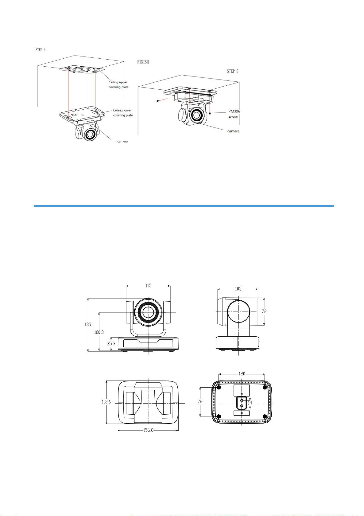
2.1.1 Dimensions........................................................................................................................................... 7
2.1.2 Accessories........................................................................................................................................... 8
2.2 MAIN FEATURES .............................................................................................................................................. 8
2.3 TECHNICAL SPECIFICATION ............................................................................................................................... 9
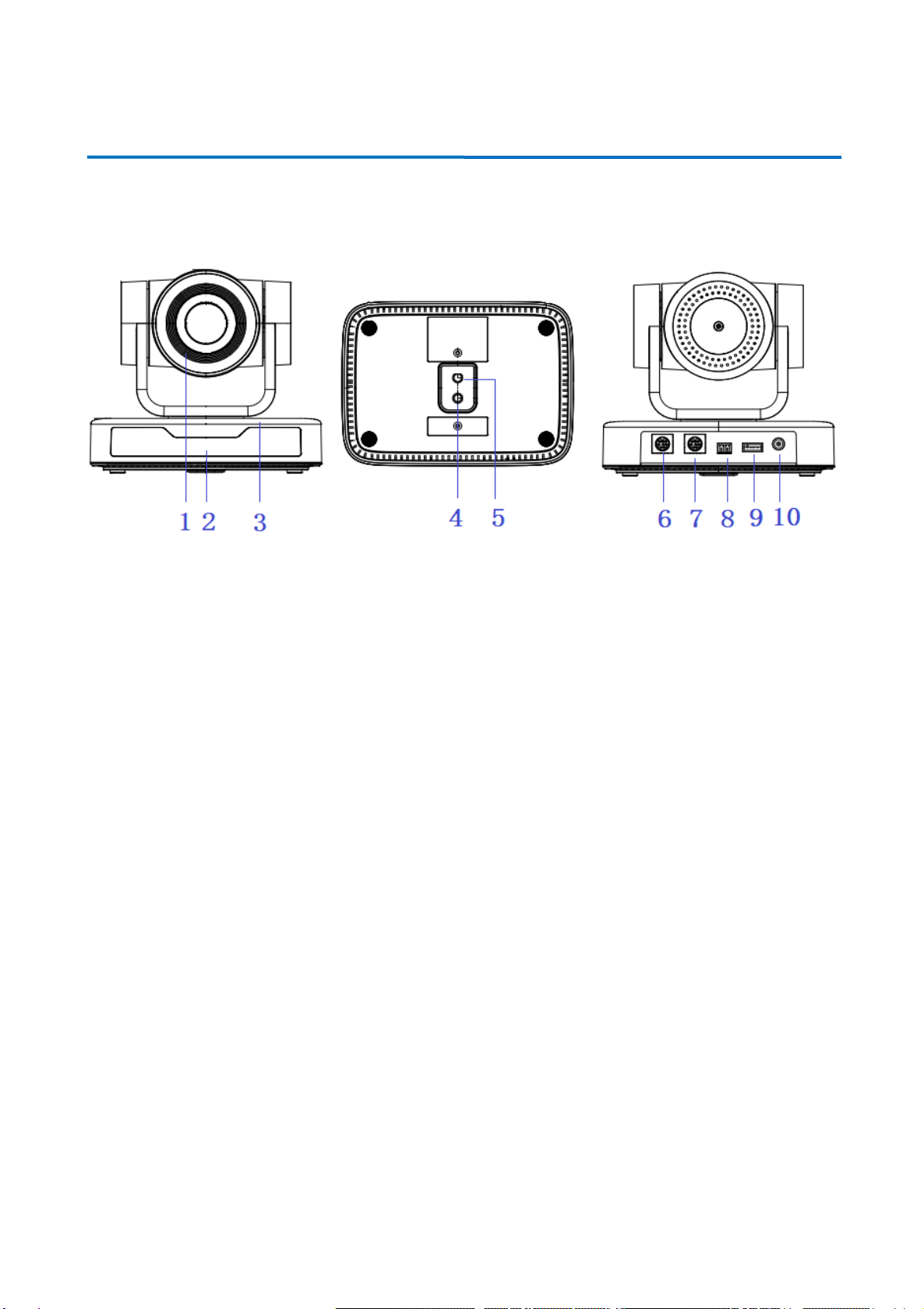
2.4 INTERFACE INSTRUCTION.................................................................................................................................. 10
2.4.1 External Interface ............................................................................................................................... 10
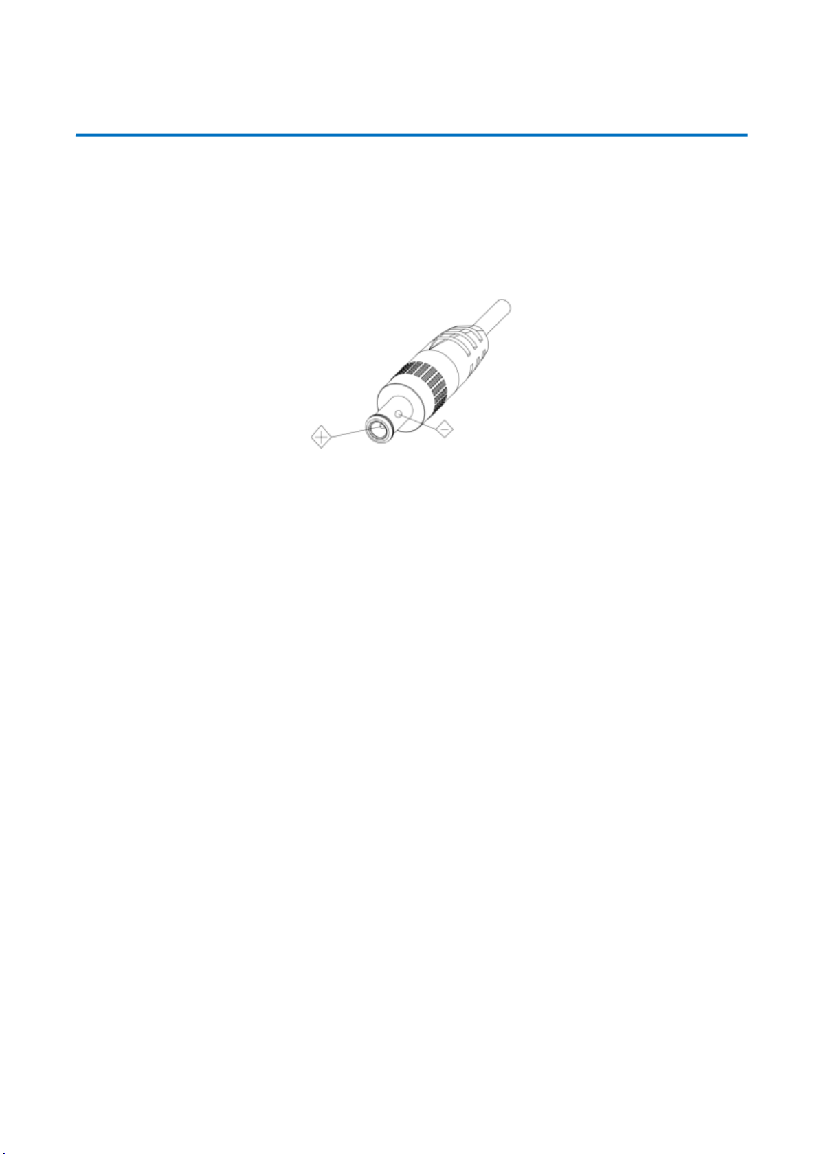
2.4.2 RS-232 Interface ..................................................................................................................................11
3. APPLICATION INSTRUCTION ............................................................................................................................ 12
3.1 VIDEO OUTPUT ............................................................................................................................................. 12
3.1.1 Power-On Initial Configuration............................................................................................................ 12
3.1.2 Video Output...................................................................................................................................... 12
3.2 Remote Controller................................................................................................................................. 13
3.2.1 Keys Instruction.................................................................................................................................. 13
3.2.1 KEYS INSTRUCTION..................................................................................................................................... 13
3.2.2 Applications........................................................................................................................................ 13
3.3 MENU SETTING........................................................................................................................................ 15
3.3.1 Main Menu...................................................................................................................................... 15
3.3.2 System Setting ................................................................................................................................. 16
3.3.3 Camera Setting ................................................................................................................................ 17
3.3.4 P/T/Z................................................................................................................................................... 20
3.3.5 Version ............................................................................................................................................... 20
3.3.6 Restore Default................................................................................................................................... 21
4.SERIAL COMMUNICATION CONTROL ................................................................................................................ 21
4.1 VISCA PROTOCOL LIST .................................................................................................................................... 22
4.1.1 Camera return command.................................................................................................................... 22
4.1.2 Camera control command................................................................................................................... 22
4.1.3 Inquiry command ............................................................................................................................... 25
4.2 PELCO-D PROTOCOL COMMAND LIST .................................................................................................................. 27
4.3 PELCO-P PROTOCOL COMMAND LIST................................................................................................................... 27

3
5. CAMERA MAINTENANCE AND TROUBLESHOOTING ......................................................................................... 28
5.1 CAMERA MAINTENANCE.................................................................................................................................. 28
5.2 TROUBLESHOOTING ........................................................................................................................................ 28
6. WARRANTY .................................................................................................................................................... 30
7. MISSION STATEMENT........................................................................................................................................ 30
8. COPYRIGHT NOTICE.......................................................................................................................................... 30

4
1. Quick Installation
1.1 Camera Interface Description
Figure 1.1 Interface
1. Camera Lens 6. RS232 Control Interface (output)
2. Remote Controller Receiver Light 7. RS232 Control Interface (input)
3. Camera Base 8. RS485 Input (left +, right-)
4. Tripod Screw Hole 9. USB2.0 Interface
5. Mounting hole 10. DC12V Input Power Supply Socket
1.2 Power on initial configuration
1) Power on: Connect DC12V power supply adapter with power supply socket.
2) Initial configuration: Power on with power indicator light on and remote control receiver light blinking, camera
head moves from bottom left to the bottom, and then goes to the HOME position (intermediate position of both
horizontal and vertical), while the camera module stretches. When remote control receiver light stops blinking,
the self-checking is finished
Note: If you set preset 0, when Power on self-test is completed, the camera automatically moves to the preset 0
position.
1.3 Video Output
This model supports USB2.0 video output.
Connect camera and computer by USB2.0 cable, choose video conference software for image.

5
1.4 Bracket mount
Note: Bracket can only be wall mounted or upside-down mounted on template and concrete wall; cannot be
installed on plasterboard.
1) Wall mount step

6
2). Upside down mount step

7
2. Product overview
2.1 Product Introduction
2.1.1 Dimensions
Figure 2.2 Camera dimension

8
2.1.2 Accessories
When you unpack, check that all the supplied accessories are included:
USB2.0 Video cable: If need USB2.0 cable to provide power but not a power adapter, USB2.0 Video cable with two
ports is needed, among which red port is for power supply and black port for transmitting USB video signals. If
using a power adapter, the general USB2.0 video cable without power supply function is ok.
2.2 Main Features
This camera offers superior performance and rich interfaces. The features include advanced ISP processing algorithms to
provide vivid images with a strong sense of depth, high resolution and accurate color rendition. It supports H.265/H.264
encoding which makes motion video fluent and clear even with less than ideal bandwidth conditions.
Superb High-definition Image: This camera employs 1/2.9-inch high quality CMOS sensor. Resolution is up to
1920x1080 with frame rate up to 30 fps.
Optical Zoom Lens: Camera has a 10X optical zoom lens.
Leading Auto Focus Technology: Leading auto focus algorithm allow for fast, accurate and stable
auto-focusing.
Low Noise and High SNR: Low Noise CMOS effectively ensure high SNR of camera video.
Control Interface:RS485, RS232, RS232 supports cascade function for convenient installation.
Supports Multiple Control Protocol: Supports VISCA, PELCO-D, PELCO-P protocols which can also be
automatically recognized.
Quiet PTZ: By adopting high accuracy step driving motor mechanism, it works extremely quiet and moves
smoothly and very quickly to designated position.
255 Presets Positions: Up to 255 presets (10 presets by remoter).
Wide Application: Tele-education, Lecture capture, Webcasting, Videoconferencing, Tele-training,
Tele-medicine, Interrogation, and Emergency command systems.
Model No
Configuration
Accessories
BG-BPTZ-3XU
BG-BPTZ-10XU
Standard
Power adapter 1piece
USB2.0 cable 1 piece
User manual 1 piece
IR Remote controller 1 piece
Rubber pad
Warranty card 1 piece
Optional
Wall mount bracket
Ceiling mount bracket

9
2.3 Technical Specification
Model
3X
10X
Camera Parameter
Sensor
1/2.9-inch high quality HD CMOS sensor
Effective Pixels
2.07 megapixel, 16:9
Video Format
H264/H265/MJPG:1920*1080P@30/25/20/15/10/5fps;1280*720P@30/25/20/15/10/5fps;
960*540@30/25/20/15/10/5fps;800*600@30/25/20/15/10/5fps;
720*576@30/25/20/15/10/5fps;720*480@30/25/20/15/10/5fps;
640*480@30/25/20/15/10/5fps;640*360@30/25/20/15/10/5fps;
352*288@30/25/20/15/10/5fps;320*240@30/25/20/15/10/5fps;
YUY2:1280*720@10/5fps;800*600@10/5fps;640*480@30/25/20/15/10/5fps;
640*360@30/25/20/15/10/5fps;
View Angel
34.1°~85°
8.8°~66°
F Value
f=3.35mm~10.05mm
f=4.34mm~41.66mm
AV
F1.7~3.0
F1.85 –F2.43
Optical Zoom
3X
10X
Minimum Illumination
0.5Lux (F1.8, AGC ON)
DNR
2D﹠3D DNR
White Balance
Auto / Manual/ One Push/(2400K~7100K)
Focus
Auto/Manual
Aperture
Auto/Manual
BLC
one/off
Video adjustment
Brightness, Color, Saturation, Contrast, Sharpness, B/W mode, Gamma curve
SNR
>55dB
Input/Output Interface
Video Interfaces
USB2.0 (type A)
Video Compression
Format
YUY2, MJPG, H.264, H.265
Control Signal Interface
RS232, RS485
Control Protocol
VISCA/Pelco-D/Pelco-P;
Power Interface
HEC3800outlrt (DC12V)
USB Features
Operating system
Windows 7, Windows8, Windows10, Mac osx, Linux
Video Compression
Format
MJPG/H264/H265
USB common protocol
UVC
PTZ Parameter
Pan Rotation
-170°~+170°
Tilt Rotation
-30°~+30°
Pan Control Speed
0.1 ~60°/sec
Tilt Control Speed
0.1~40°/sec
Preset Speed
Pan:48°/sec,Tilt:38°/sec
Preset Number
255 presets (10 presets by remote controller)
Other Parameter
Input Voltage
12V
Input Current
0.42A(max)

10
Consumption
5W(max)
Store Temperature
-40℃~+70℃
Store Humidity
20%~90%
Working Temperature
-10℃~+50℃
Working Humidity
20%~80%
Dimension
156.8mm×112.6mm×139.5mm
Weight
1kg
Working Environment
Indoor
Accessory
Power Supply, Remote Controller, USB2.0 cable, Manual ,Warranty card, Packing list
Optional Accessory
Bracket
2.4 Interface Instruction
2.4.1 External Interface
1)External interface:RS232 in \out, USB2.0, A-in, DC12V
Figure 2.4 external interface diagram

11
2.4.2 RS-232 Interface
1)RS-232 Interface
Computer or keyboard and camera connection
method
Camera
WindowsDB-9
1.DTR
1.DCD
2.DSR
2.RXD
3.TXD
3.TXD
4.GND
4.DTR
5.RXD
5.GND
6.GND
6.DSR
7.IR OUT
7.RTS
8.NC
8.CTS
9.RI
2)RS-232 Mini-DIN 8-pin Port Definition
3)RS232(DB9) Port Definition
NO.
Port
Definition
1
DTR
Data Terminal Ready
2
DSR
Data Set Ready
3
TXD
Transmit Data
4
GND
System Ground
5
RXD
Receive Data
6
GND
System Ground
7
IR OUT
IR Commander Signal
8
NC
No Connection
NO.
Port
Definition
1
DCD
Data Carrier Detect
2
RXD
Receive Data
3
TXD
Transmit Data
4
DTR
Data Terminal Ready
5
GND
System Ground
6
DSR
Data Set Ready

12
4)VISCA networking as shown below:
Camera cascade connection method
Camera1
Camera 2
1.DTR
1.DTR
2.DSR
2.DSR
3.TXD
3.TXD
4.GND
4.GND
5.RXD
5.RXD
6.GND
6.GND
7.IR OUT
7.OPEN
8. NC
8.OPEN
Note: this model has RS232 input and output interface, so you can cascade as the above way.
3. Operating Instructions
3.1 Video Output
3.1.1 Power-On Initial Configuration
After connecting the power, the camera will initiate self-test mode. The IR indicator light will start flashing.
When the camera returns to the HOME position (middle position for P/T) and lens finishes zoom in/out, the
self-testing is finished. The IR led will stop flashing. If the preset 0 is set, the camera will rotate to the (0) preset
position after initial configuration.
3.1.2 Video Output
Connect the video output cable according to the interface diagram.
USB2.0 output: Connect this product with computer USB3.0 interface (blue), open the Device Manager to
see whether there is an image device and whether the Universal Serial Bus controllers recognize USB3.0 device.
After the computer identifies the device an image will be displayed.
7
RTS
Request to Send
8
CTS
Clear to Send
9
RI
Ring Indicator

13
3.2 Remote Controll
3.2.1 Keys Instruction
3.2.1 Key Description
1. Power/Standby Key
Press and hold for 3 seconds to place the camera into standby mode. Press and hold for 3 seconds a
second time and the camera will self-test again and return to the HOME position. Note: Camera will
default to preset 0 if no command is sent within 12 seconds of power on.
2. Camera Select
Select the ID of the camera you wish to control.
3. Number Key
Set or run preset 0-9
4,* # Key
Used for command modifiers
5. Focus Control Key
Auto: Activate auto focus mode.
Manual: Activate manual focus mode.
+/-: Adjust focus in manual focus mode.
6. Zoom Control Key
Zoom+: Zoom In
Zoom-: Zoom Out
7. Set or Clear Preset key:
Set Preset: Press and hold while selecting desired number key to record a preset.
Clear Preset key: Press and hold while selecting desired number key to clear a preset.
8. Pan/Tilt Control Key
Tilt camera up
Tilt camera down
Pan camera left
Pan camera right
HOME: Return to the middle position/ confirm on-screen menu selection.
9. BLC ON/OFF
Turn on or off remote control button backlighting.
10. MENU
Enter or exit on-screen menu/previous menu.
11. Camera IR Remote Control Address Setting
【*】+【#】+【F1】:Camera Address No.1
【*】+【#】+【F2】:Camera Address No. 2
【*】+【#】+【F3】:Camera Address No. 3
【*】+【#】+【F4】:Camera Address No. 4
3.2.2 Applications
Following initialization, the camera can receive and execute the IR commands. The indicator will flash when the camera receives
a command. Users can control the pan/tilt/zoom, settings, and run preset positions via the IR remote controller.

14
Key Instruction:
1. In this instruction, “press the key” means a click rather than a long-press, and a special note will be given if a long-press for
more than one second is required.
2. When a key-combination is required, do it in sequence. For example,“ 【*】+【#】+【F1】”means press“【*】”first and then
press“【#】” and last press“【F1】”.
1) Camera Selection
Select the camera address to control.
2) Pan/Tilt Control
Up: press Down: press
Left: press Right: press
Back to middle position: press“【HOME】”
Press and hold the up/down/left/right key, the pan/tilt will keep
running, from slow to fast, until it runs to the endpoint; the
pan/tilt running stops as soon as the key is released.
3) Zoom Control
ZOOM IN: press “ZOOM “ key
ZOOM OUT: press “ZOOM ” key
Press and hold the key, the camera will keep zooming in or
zooming out and stops as soon as the key is released.
4) Focus Control
Focus (near):Press “【focus+】” key (Valid only in manual focus
mode)
Focus (far): Press “【focus-】”key (Valid only in manual focus
mode)
Auto Focus: Support
Manual Focus: Support
Press and hold the key, the action of focus will keep continue and
stops as soon as the key is released.
5) BLC Setting
BLC ON / OFF: support

15
6) Presets Setting, Running, Clearing
1. Preset setting: to set a preset position, the users should press
the “【SET PRESET】” key first and then press the number key 0-9
to set a relative preset,
Note: 10 preset positions in total are available by remote
controller.
2. Preset Running: Press a number key 0-9 directly to run a
relative preset.
Note: Action in vain if a relative preset position is not existed.
3. Preset clearing: to clear a preset position, the user can press
the “【CLEAR PRESET】” key first and then press the number key
0-9 to clear the relative preset;
Note : press the“【#】” key three times continually to cancel all
the presets.
7) Camera Remote Controller Address Setting
【*】+【#】+【F1】:Camera Address No.1
【*】+【#】+【F2】:Camera Address No. 2
【*】+【#】+【F3】:Camera Address No. 3
【*】+【#】+【F4】:Camera Address No. 4
3.3 MENU SETTINGS
3.3.1 Main Menu
In normal working mode, press 【MENU】key to display the menu, using scroll arrow to point at or highlight the
selected items.

16
SETUP:System setting
CAMERA :Camera setting
P/T/Z:Pan tilt setting
VERSON:camera version setting
Restore Default:Reset setting
[↑↓] Select:for selecting menu
[← →] Change Value:for modify parameters
[MENU] Back:Press [MENU] to return
[Home] OK:Press [Home] to confirm
3.3.2 System Setting
Move the pointer to the (Setup) in the Main Menu, click the【HOME】key and enter into the (System Setting)
as shown below,
PROTOCOL: VISCA/Pelco-P/Pelco-D/Auto
SETUP
================
Protocol Auto
Visca Address 1
Visca Address Fix OFF
PELCO-PAddress 1
PELCO-D Address 1
Baudrate 9600
Auto Filp ON
[↑↓]Select [←→]Change Value
[Menu]Back
[↑↓]选择 [←→]修改
[菜单]返回
MENU
================
(Setup)
(Camera)
(P/T/Z)
(Version)
(Restore Default)
[↑↓]Select [←→]Change Value
[Menu]Back[Home]OK

17
VISCA ADDRESS: VISCA=1~7 Pelco-P=1~255 Pelco-D = 1~255
BAUD RATE : 2400/4800/9600/115200
VISCA ADDRESS FIX : On/Off
3.3.3 Camera Setting
Move the pointer to the (CAMERA) in the Main Menu, click the【HOME】key and enter the (CAMERA) as follow:
EXPOSURE: Enter Exposure setting
COLOR: Enter color setting
Image: Enter image setting
Focus: Enter focus setting
Noise Reduction: Enter noise reduction
1) EXPOSURE SETTING
Move the pointer to the (EXPOSURE) in the Main Menu, click the【HOME】and enter the (EXPOSURE SET) as follow,
Mode: Auto, Manual, Shutter priority, Iris priority and Brightness priority.
EV: On/Off (only available in auto mode)
EXPOSURE
=================
Mode Auto
EV OFF
BLC OFF
Flicker 50Hz
G.Limit 3
DRC 2
[↑↓]Select [←→]Change Value
[Menu]Back
CAMERA
=================
(Exposure)
(Color)
(Image)
(Focus)
(Noise Reduction)
Style Default
[↑↓]Select [←→]Change Value
[Menu]Back [Home]OK

18
Compensation Level: -7~7 (only available in auto mode when EV is ON)
BLC: ON/OFF for options (only available in auto mode)
Anti-Flicker: OFF/50Hz/60Hz for options (only available in Auto/Iris priority/Brightness priority modes)
Gain Limit: 0~15(only available in Auto/ Iris priority /Brightness priority mode)
WDR: Off,1~8
Shutter
Priority:1/25,1/30,1/50,1/60,1/90,1/100,1/120,1/180,1/250,1/350,1/500,1/1000,1/2000,1/3000,1/4000,1/6000,1/10000(only
available in Manual and Shutter priority mode)
IRIS Priority: OFF,F11.0,F9.6,F8.0,F6.8,F5.6,F4.8,F4.0,F3.4,F2.8,F2.4,F2.0,F1.8(only available in Manual and Iris priority mode)
Brightness: 0~23 (only available in Brightness priority mode)
2)COLOR SETTING
Move the pointer to the (COLOR) in the Main Menu, click the【HOME】and enter the (COLOR SET) as follow:
WB Mode: Auto, 3000K, 3500K, 4000K, 4500K, 5000K, 5500K, 6000K, 6500K, 7000K, Manual, One Push
Red Gain: 0~255(only available in Manual mode)
Blue Gain: 0~255(only available in Manual mode)
Saturation: 60%,70%,80%,90%,100%,110%,120%,130%
Hue: 0~14
AWB Sensitivity: high/middle/low
Color Style: Default, style1~4.
Color Temp: high/middle/low
3) IMAGE
Move the pointer to the (IMAGE) in the Menu, click the【HOME】and enter the (IMAGE) as follow,
COLOR
================
WB Mode Auto
RG Tuning -10
BG Tuning -10
Saturation 100%
Hue 7
AWB Sensitivity High
[↑↓]Select [←→]Change Value
[Menu]Back

19
Brightness: 0~14
Contrast: 0~14
Sharpness: 0~15
Flip-H: On/Off
Flip-V: On/Off
B&W Mode: color, black/white
Gamma: default, 0.47, 0.50, 0.52, 0.55
DZoom: digital zoom options: On/Off
DCI: Dynamic Contrast: Off,1~8
4) FOCUS
Move the pointer to the (FOCUS) in the Menu, click the【HOME】and enter the (FOCUS) as follow,
Focus Mode: Auto, manual
AF-Zone: Up, middle, down
AF-Sensitivity: High, middle, low
5) NOISE REDUCTION
Move the pointer to the (NOISE REDUCTION) in the Menu, click the【HOME】and enter the (NOISE REDUCTION) as follow,
FOCUS
================
Focus Mode Auto
AF-Zone Center
AF-Sensitivity Low
[↑↓]Select [←→]Change
Value
[Menu]Back
IMAGE
================
Brightness 7
Contrast 8
Sharpness 3
Flip-H OFF
Flip-V OFF
B&W-Mode Color
Gamma Default
DCI Close
Low-Light Mode OFF
[↑↓]Select [←→]Change Value
[Menu]Back
This manual suits for next models
1
Table of contents
Other BZB Gear Camcorder manuals

BZB Gear
BZB Gear BG-BWEB-S User manual

BZB Gear
BZB Gear BG-PACKSHOT-C10X User manual

BZB Gear
BZB Gear BG-B20SA User manual

BZB Gear
BZB Gear BG-B20HS User manual

BZB Gear
BZB Gear BG-PACKSHOT-C10X User manual

BZB Gear
BZB Gear BG-LVPTZ-10XHSP User manual

BZB Gear
BZB Gear BG-VPTZ-10HSU3 User manual

BZB Gear
BZB Gear BG-BPTZ-10XU User manual

BZB Gear
BZB Gear BG-ND-20XHSRP User manual

BZB Gear
BZB Gear BG-CAM-USB4K User manual