C.P. Electronics ALC15 User manual

ALC15
Robust, IP66, surface mounted, wall, photocell switch, basic switching
Robust, IP66, Oberächenmontage, Wand, Lichtschrankenschalter, Grundschaltung
Robusto, IP66, montaje en supercie, pared, interruptor de fotocelda, conmutación básica
Robusto, IP66, montagem em superfície, parede, interruptor de fotocélulas, permutação básica
Robuste, IP66, xation en applique, mur, interrupteur photoélectrique, commutation de base
Interruttore a fotocellula resistente, IP66, installazione superciale, a parete, con commutazione di base
Robuust, IP66, opbouw, wand, fotocelschakelaar, basisschakeling
Датчик освещенности, IP66, накладной, настенный, коммутация - реле
Downloads and Videos | Downloads und Videos | Descargas y Videos | Descargas e Videos |
Téléchargements & Vidéos | Downloads e Video | Downloads en Video’s | Загрузки и Видео
cpelectronics.co.uk/cp/128
Warning | Warnung | Advertencia |
Aviso | Attention | Attenzione |
Waarschuwing | Внимание
EN This device should
be installed by a qualied
electrician in accordance with
the latest edition of the IEE
wiring regulations.
DE Dieses Gerät ist
ausschließlich von qualizierten
Elektrofachkräen zu installieren.
ES Sólo un electricista
cualicado debe instalar este
dispositivo.
PT Somente um eletricista
qualicado deve instalar este
dispositivo.
FR Seul un électricien
qualié peut installer ce
dispositif.
IT Il dispositivo deve
essere installato da un
elettricista qualicato.
NL Dit apparaat moet
worden geïnstalleerd door een
gekwaliceerde elektricien.
RU Это устройство
должно быть установлено
квалифицированным
электриком.
Dimensions (mm) | Abmessungen (mm) | Dimensiones (mm) | Dimensões (mm) | Dimensioni (mm) |
Dimensies (mm) | Размеры (мм)
39
15
95
95
79
WD128 Issue 8 Installation Guide
ALC15

2
Wiring | Verkabelung | Cableado | Ligações | Câblage | Cablaggio | Bedrading | Кабель
EN The unit has a voltage free changeover output which can
be used to switch, say, a BMS or lighting control system as well as
switching a load directly. To switch a load directly link the L and
COM terminals and take the output from the NO terminal.
• Where possible site the sensor as high as possible on a north
facing vertical surface
• Avoid locating the ALC15 in direct sight of the light that it is
controlling.
• Ensure that all cable entry to the enclosure is via suitable cable
glands and seal with silicone sealant where appropriate
• If it is necessary to screw through the rear of the enclosure
ensure that any holes are covered with the caps provided and
sealed with silicone sealant where appropriate.
DE Das Gerät verfügt über einen spannungsfreien
Umschaltausgang, mit dem beispielsweise ein BMS- oder
Lichtsteuerungssystem sowie eine Last direkt geschaltet werden
können. Wenn eine Last direkt geschaltet werden soll, verbinden
Sie die Klemmen L und COM und nehmen Sie den Ausgang an
Klemme NO ab.
• Platzieren Sie den Sensor in möglichst großer Höhe an einer
nach Norden gerichteten senkrechten Fläche
• Platzieren Sie den ALC15 nicht direkt vor der Beleuchtung, die
gesteuert werden soll.
• Achten Sie darauf, dass alle Kabel durch geeignete
Kabelverschraubungen in das Gehäuse geführt werden und
dichten Sie diese gegebenenfalls mit Silikondichtmittel ab
• Wenn durch die Rückseite des Gehäuses geschraubt werden
muss, müssen alle Löcher mit den mitgelieferten Kappen
abgedeckt und gegebenenfalls mit Silikondichtmittel
abgedichtet werden.
ES La unidad tiene una salida de cambio libre de tensión que
puede usarse para cambiar, digamos, un BMS o sistema de control
de iluminación y para conmutar una carga directamente. Para
cambiar una carga directamente, vincule los terminales L y COM y
saque la salida del terminal NO.
• Siempre que sea posible, sitúe el sensor lo más alto posible en
una supercie vertical orientada al norte
• Evite colocar el ALC15 directamente al alcance de la luz que está
controlando.
• Asegúrese que la entrada del cable a la carcasa se realiza a
través de prensacables y sellos adecuados con sellado de
silicona siempre que sea apropiado
• Si es necesario atornillar a través de la carcasa, asegúrese de
que los oricios estén cubiertos con las tapas proporcionadas y
sellados con sellador de silicona siempre que sea apropiado.
PT A unidade possui uma saída de permutação sem tensão
que pode ser utilizada para permutar, por exemplo, um BMS ou
um sistema de controlo de iluminação, assim como para permutar
uma carga diretamente. Para permutar uma carga diretamente,
interligue os terminais L e COM, e retire a produção do terminal NO.
• Sempre que possível, coloque o sensor o mais alto possível
numa superfície vertical direcionada para norte
• Evite colocar o ALC15 sob a visão direta da luz que está a
controlar.
• Certique-se de que todas as entradas de cabo junto do
recetáculo são efetuadas por meio de glândulas de cabo
adequadas e sele com vedante de silicone onde for adequado
• Caso seja necessário aparafusar através da parte traseira do
recetáculo, certique-se de cobrir quaisquer orifícios com as
tampas fornecidas e de selar com vedante de silicone onde for
adequado.
FR L’unité a une sortie à inverseur sans potentiel qui peut être
utilisée pour commuter, par exemple, un BMS ou un système de
commande d’éclairage ou commuter directement une charge.
Pour commuter directement une charge, reliez les terminaux L et
COM et faites revenir la sortie depuis le terminal NO.
• Si possible, placez le capteur aussi haut que possible sur une
surface verticale orientée vers le nord
• Évitez de placer l’ALC15 de façon à ce qu’il ait une vision directe
de la lumière qu’il contrôle.
• Assurez-vous que toutes les entrées des câbles dans l’enceinte
se font via des presse-étoupes adaptés et scellez avec du mastic
silicone si besoin
• S’il est nécessaire de visser à l’arrière de l’enceinte, assurez-vous
que tous les trous sont recouverts par les bouchons fournis et
scellés avec du mastic silicone si besoin.
IT L’unità presenta un output di conversione privo di tensione
che può essere utilizzato per commutare, ad esempio, un BMS o
un sistema di controllo dell’illuminazione oltre che commutare
direttamente un carico. Per commutare direttamente un carico,
collegare i terminali L e COM e prendere l’output dal terminale NO.
• Se possibile, collocare il sensore quanto più in alto possibile su
una supercie verticale rivolta a nord
• Evitare di posizionare ALC15 direttamente a vista della luce che
controlla
• Assicurarsi che qualsiasi ingresso di cavi nell’alloggiamento
avvenga tramite passacavi adeguati e sigillare con silicone, se
necessario
• Se è necessario avvitare passando per il retro dell’alloggiamento,
assicurarsi che tutti i fori vengano coperti con i cappucci in
dotazione e sigillati con silicone, se necessario.
NL Het apparaat hee een spanningsvrije wisseluitgang die
gebruikt kan worden om bijvoorbeeld een regelsysteem voor BMS
of verlichting te schakelen en om een belasting direct te schakelen.
Koppel om een belasting direct te schakelen de L- en COM-
klemmen en haal de uitgang van de NO-klem.
• Plaats waar mogelijk de sensor zo hoog mogelijk, op een naar
het noorden gericht verticaal oppervlak
• Probeer te vermijden dat de ALC15 direct in het zicht van het
licht staat dat geregeld wordt.
• Zorg ervoor dat alle kabelingangen naar de behuizing via
geschikte kabelwartels worden aangebracht en waar nodig met
siliconenkit zijn afgedicht
• Als door de achterzijde van de behuizing moet worden
geschroefd, zorg er dan voor dat eventuele openingen met
de meegeleverde doppen zijn afgedekt en waar nodig met
siliconenkit zijn afgedicht.
RU Устройство имеет беспотенциальный перекидной
контакт, который можно использовать например, для системы
BMS или системы управления освещением, а также для
непосредственной коммутации нагрузки. Для включения
нагрузки напрямую соедините клеммы L и COM и используйте
выход с клеммы NO.
• По возможности, размещайте датчик как можно выше на
вертикальной поверхности, обращенной к северу.
• По возможности, размещайте датчик как можно выше на
вертикальной поверхности, обращенной к северу.
• Убедитесь, что все кабельные вводы в корпус проходят
через соответствующие кабельные уплотнения, и если
необходимо, воспользуйтесь силиконовым герметиком.
• При необходимости, закрепите заднюю часть корпуса с
помощью шурупов убедитесь, что все отверстия закрыты
заглушками, идущими в комплекте, и по необходимости
залиты силиконовым герметиком.

3
NLNC NO
COM
1
3
2
EN Key
1. Neutral
2. Live
3. 10A circuit protection if
required
DE Zeichenerklärung
1. Neutral
2. Netzspannungsführend
3. 10A Kurzschlusssicherung,
falls nötig
ES Leyenda
1. Neutro
2. Fase
3. 10A protección de circuito,
en caso necesario
PT Legenda
1. Neutro
2. Fase
3. 10A proteção do circuito,
caso necessário
FR Légende
1. Neutre
2. Phase
3. 10A protection du circuit si
nécessaire
IT Legenda
1. Neutro
2. Fase
3. 10A protezione del circuito,
se necessario
NL Legenda
1. Nul
2. Fase
3. 10A beveiliging indien nodig
RU Условные обозначения
1. Нейтральный
2. Фаза
3. 10А защита цепи при
необходимости

4
EN Installation
EN This device works at mains potential.
Be sure to take care when working with
electricity.
DE Dieses Gerät arbeitet bei
Netzspannung. Gehen Sie beim Arbeiten an
elektrischen Anlagen stets umsichtig vor.
ES Este dispositivo funciona con la
tensión de la red eléctrica. Asegúrese
de tener cuidado cuando trabaje con
electricidad.
PT Este dispositivo funciona totalmente
por meio da corrente elétrica. Tenha
cuidado ao trabalhar com eletricidade.
FR Cet appareil fonctionne avec la
capacité du réseau. Veillez à être prudent
lorsque vous travaillez avec l’électricité.
IT Questo dispositivo funziona al
potenziale di rete. Prestare attenzione
quando si lavora in presenza di elettricità.
NL Dit apparaat werkt op netspanning.
Wees voorzichtig wanneer u met
elektriciteit werkt.
RU Данное устройство работает
от сети. Необходимо соблюдать
осторожность при работе с
электричеством.
1. Make sure the load is connected and in working order.
2. Isolate the mains supply to the circuit at the main consumer unit.
3. Connect the controller via the terminal block. Live supply to the L
terminal, Neutral to the N terminal.
4. For direct switching applications link L to COM and take the output from
the NO terminal.
5. Set the TIME thumbwheel to AUTO OFF by turning fully anticlockwise
6. Set the LUX thumbwheel to LATE by turning fully clockwise.
7. Set the DIFF (dierential) thumbwheel half way.
8. Power the unit up.
9. The lights will not come on until the ambient light level is very low.
10. Adjust the LUX level and dierential using the guide overleaf.
11. Finally set the TIME thumbwheel to AUTO OFF or the desired time setting.
Warning | Warnung | Advertencia | Aviso | Attention | Attenzione | Waarschuwing | Внимание
Adjusting the Lux level
1. The best time to set the LUX level is when the unit is just required to turn on.
2. Leave the TIME and DIFF thumbwheels set as above.
3. Turn the LUX thumbwheel very slowly anticlockwise towards the EARLY position until the lights come on.
4. There is a 2 minute time delay to prevent nuisance switching. This is automatically disabled whenever the LUX thumbwheel is turned,
and then re-instated automatically aer a further 2 minutes.
5. Turning the LUX thumbwheel to EARLY switches the unit earlier in the day, i.e. when ambient conditions are lighter. Turning to LATE
switches the unit later in the day, i.e. when ambient conditions are darker.
Adjusting the dierential
1. Aer the unit has turned on, the dierential is used to determine at what level of measured light to switch o again. It is only relevant in
AUTO OFF mode.
2. If the dierential is set to minimum the unit will turn o when the measured light is only a tiny bit greater than the level at which it
turned on.
3. If the dierential is set to maximum the unit will turn o then the measured light is much greater than the level at which it turned on.
4. If, say, the unit is set to turn on at dusk, set the dierential lower (anticlockwise) if you want the lights to turn o again early in the
morning and set the dierential higher (clockwise) if you want the lights to turn o again when it is much lighter.
5. The dierential is also useful if the unit can see the lights which it is controlling. In this case increasing the dierential will prevent
cycling of the output.

5
DE Installation
1. Überprüfen Sie, ob die Last angeschlossen und funktionstüchtig ist.
2. Trennen Sie die Stromversorgung an der Schaltung am Hauptverbraucher.
3. Schließen Sie die Steuerung über den Klemmenblock an.
Stromversorgung an Klemme L, Nullleiter an Klemme N.
4. Bei direkt schaltenden Anwendungen verbinden Sie L mit COM und
nehmen Sie den Ausgang an Klemme NO ab.
5. Drehen Sie den Drehregler TIME vollständig gegen den Uhrzeigersinn in
Stellung AUTO OFF.
6. Drehen Sie den Drehregler LUX vollständig im Uhrzeigersinn in Stellung
LATE.
7. Drehen Sie den Drehregler DIFF (Dierenz) in die Mittelposition.
8. Schalten Sie das Gerät ein.
9. Die Beleuchtung wird erst eingeschaltet, wenn das Umgebungslicht sehr
schwach ist.
10. Stellen Sie den LUX-Pegel und die Dierenz anhand der umseitigen
Anleitung ein.
11. Drehen Sie schließlich den Drehregler TIME auf AUTO OFF oder die
gewünschte Zeiteinstellung.
Einstellung der Lichtstärke (LUX-Pegel)
1. Die beste Zeit zum Einstellen des LUX-Pegels ist die Tageszeit, zu der das Gerät eingeschaltet werden soll.
2. Lassen Sie die Drehregler TIME und DIFF in den oben beschriebenen Stellungen.
3. Drehen Sie den Drehregler LUX sehr langsam gegen den Uhrzeigersinn in Richtung der Stellung EARLY, bis die Beleuchtung
eingeschaltet wird.
4. Zur Vermeidung von störenden Schaltvorgängen ist eine Zeitverzögerung von 2 Minuten eingerichtet. Diese wird automatisch
deaktiviert, wenn der Drehregler LUX betätigt wird, und wird nach weiteren 2 Minuten automatisch wieder aktiviert.
5. Das Drehen des LUX-Drehreglers in Richtung EARLY bewirkt ein früheres Einschalten des Geräts, d.h. wenn das Umgebungslicht
stärker ist. Das Drehen in Richtung LATE bewirkt ein späteres Einschalten des Geräts, d.h. wenn das Umgebungslicht schwächer ist.
Einstellung der Dierenz
1. Nach dem Einschalten wird anhand der Dierenz bestimmt, bei welcher gemessenen Beleuchtungsstärke das Gerät wieder
ausgeschaltet werden soll. Dies ist nur im Modus AUTO OFF von Bedeutung.
2. Wenn der Dierenzwert auf Minimum eingestellt ist, wird das Gerät ausgeschaltet, sobald die gemessene Beleuchtungsstärke nur ein
wenig größer ist als beim Einschalten.
3. Wenn der Dierenzwert auf Maximum eingestellt ist, wird das Gerät erst dann ausgeschaltet, wenn die gemessene
Beleuchtungsstärke viel größer ist als beim Einschalten.
4. Wenn das Gerät beispielsweise auf Einschalten in der Dämmerung eingestellt ist, dann stellen Sie die Dierenz niedriger (gegen den
Uhrzeigersinn) ein, wenn die Beleuchtung am frühen Morgen wieder ausgeschaltet werden soll, und höher (im Uhrzeigersinn), wenn
die Beleuchtung erst ausgeschaltet werden soll, wenn es sehr hell ist.
5. Die Dierenzfunktion ist ebenfalls nützlich, wenn sich die zu steuernde Beleuchtung im Erfassungsbereich des Geräts bendet. In
diesem Fall wird durch ein Erhöhen des Dierenzwerts eine Ausgangsschleife verhindertcycling of the output.

6
ES Instalación
1. Asegúrese de que la carga esté conectada y funcionando correctamente.
2. Aísle el suministro de la red eléctrica al circuito en la unidad principal del
consumidor.
3. Conecte el controlador a través del bloque de terminales. Suministre con
corriente al terminal L, neutro al terminal N.
4. Para aplicaciones de conmutación directa, vincule L a COM y saque la
salida del terminal NO.
5. Establezca la rueda selectora TIME (Tiempo) a AUTO-OFF girándola en
sentido contrario a las agujas del reloj
6. Establezca la rueda selectora LUX a LATE girándola completamente en
sentido de las agujas del reloj.
7. Establezca la rueda selectora DIFF (diferencial) a la mitad.
8. Encienda la unidad.
9. Las luces no se encenderán hasta que el nivel de luz ambiental sea muy
bajo.
10. Ajuste el nivel LUX y el diferencial usando la guía al dorso.
11. Finalmente establezca la rueda selectora TIME a AUTO OFF o al ajuste
horario deseado.
Ajustar el nivel LUX
1. El mejor momento para establecer el nivel LUX es cuando solo se requiera que la unidad se encienda.
2. Deje las ruedas selectoras TIME y DIFF como se ha indicado anteriormente.
3. Gire la rueda selectora LUX muy lentamente en sentido contrario a las agujas del reloj hacia la posición EARLY hasta que las luces se
enciendan.
4. Existe un retraso de 2 minutos de tiempo para evitar que se encienda de forma molesta. Esto se deshabilita automáticamente siempre
que se gire la rueda selectora LUX, y luego se reactiva automáticamente tras otros dos minutos.
5. Al girar la rueda selectora LUX a EARLY se enciende la unidad antes, es decir, cuando hay más luz ambiental. Al girar a LATE se
enciende la unidad más tarde, es decir, cuando hay menos luz ambiental.
Ajustar el diferencial
1. Una vez encendida la unidad, el diferencial se usa para determinar a qué nivel de luz medida apagar de nuevo. Solo es relevante en
modo AUTO OFF.
2. Si el diferencial se establece al mínimo, la unidad se apagará cuando la luz medida sea solo un poco mayor que el nivel al cual se
enciende.
3. Si el diferencial se establece al máximo, la unidad se apagará cuando la luz medida sea mucho mayor que el nivel al cual se encendió.
4. Si, digamos, la unidad se congura para que se encienda al amanecer, establezca el diferencial más bajo (en sentido contrario a las
agujas del reloj) si desea que las luces se apaguen de nuevo temprano por la mañana y establezca el diferencial más alto (en sentido de
las agujas del reloj) si desea que las luces se apaguen de nuevo cuando haya mucha más luz.
5. El diferencial también es útil si la unidad puede ver las luces que está controlando. En este caso, aumentar el diferencial evitará que se
realice un ciclo de la salidacycling of the output.

7
PT Instalação
1. Certique-se de que a carga se encontra ligada e em bom funcionamento.
2. Isole a corrente principal do circuito na unidade de consumo principal.
3. Ligue o controlador através do bloco de terminais. Corrente fornecida para
o terminal L e Neutro para o terminal N.
4. Para aplicações de permutação direta, ligue o L ao OM, e retire a produção
do terminal NO.
5. Coloque o seletor rotativo TIME (Hora) na posição AUTO OFF (Automático
desligado) girando-o totalmente na direção oposta aos ponteiros do
relógio.
6. Coloque o seletor rotativo LUX na posição LATE (Tarde) girando-o
totalmente na direção oposta aos ponteiros do relógio.
7. Coloque o seletor rotativo DIFF (diferencial) a meia posição.
8. Acione a unidade.
9. As luzes não se acendem enquanto o nível de luz ambiente estiver
demasiado baixo.
10. Ajuste o nível LUX e o diferencial, utilizando o verso-guia.
11. Finalmente, coloque o seletor rotativo TIME (Hora) na posição AUTO OFF
(Automático desligado) ou na denição de tempo desejado.
Ajuste do nível Lux
1. A melhor altura para congurar o nível LUX é quando a unidade necessita de ser ligada.
2. Deixe os seletores rotativos TIME (Tempo) e DIFF (Diferencial) congurados como acima indicado.
3. Gire o seletor rotativo LUX muito lentamente na direção oposta aos ponteiros do relógio na direção da posição EARLY (Cedo) até as
luzes se acenderem.
4. Existe um atraso de dois (2) minutos para evitar uma permutação com problemas. Isto é desativado automaticamente sempre que o
seletor rotativo LUX for girado e depois é realocado automaticamente após um período adicional de dois (2) minutos.
5. Ao girar o seletor rotativo LUX para a posição EARLY (Cedo) permuta a unidade para mais cedo no dia, ou seja, quando as condições
ambiente estiverem mais claras. Ao girar o seletor rotativo para a posição LATE (Tarde) permuta a unidade para mais tarde no dia, ou
seja, quando as condições ambiente estiverem mais escuras.
Ajuste do diferencial
1. Depois de a unidade ser ligada, o diferencial é utilizado para determinar qual o nível de luz medida que deve gerar novo desligamento.
É apenas relevante no modo AUTO OFF (Automático desligado).
2. Se o diferencial for congurado no mínimo, a unidade desliga-se quando a luz medida é apenas um pouco superior ao nível no qual foi
acionada.
3. Se o diferencial for congurado no máximo, a unidade desliga-se quando a luz medida é muito superior ao nível no qual foi acionada.
4. Se, por exemplo, a unidade for congurada para se ligar ao anoitecer, coloque o diferencial a um nível inferior (na direção oposta
aos ponteiros do relógio) se desejar que as luzes voltem a desligar-se cedo de manhã, e coloque o diferencial a um nível superior (na
direção dos ponteiros do relógio) se desejar que as luzes voltem a desligar-se quando houver mais luz.
5. O diferencial também é útil caso a unidade possa visualizar as luzes que está a controlar. Neste caso, aumentar o diferencial evita a
deslocação cíclica da produção.

8
FR Installation
1. Assurez-vous que la charge est connectée et en état de marche.
2. Isolez l’alimentation secteur du circuit sur l’unité centrale de
consommation.
3. Connectez le contrôleur via le bornier. Alimentation sous tension au
terminal L, Neutre au terminal N.
4. Pour des applications de commutation directe, reliez L à COM et faites
revenir la sortie depuis le terminal NO.
5. Réglez la molette TIME sur AUTO OFF en la tournant complètement dans le
sens antihoraire
6. Réglez la molette LUX sur LATE en la tournant complètement dans le sens
horaire.
7. Réglez la molette DIFF (diérentiel) à mi-chemin.
8. Allumez l’unité.
9. Les lumières s’allument uniquement lorsque la luminosité ambiante
devient très faible.
10. Ajustez le niveau LUX et le diérentiel à l’aide du guide au verso.
11. Enn, réglez la molette TIME sur AUTO OFF ou sur le réglage de temps
souhaité.
Ajuster le niveau Lux
1. Le meilleur moment pour régler le niveau LUX est lorsque l’unité vient d’être allumée.
2. Laissez les molettes TIME et DIFF sur les réglages indiqués ci-dessus.
3. Tournez très lentement la molette LUX dans le sens antihoraire vers la position EARLY jusqu’à ce que les lumières s’allument.
4. Il y a un délai de 2 minutes pour éviter une commutation indésirable. Ceci est automatiquement désactivé lorsque la molette LUX est
tournée, puis rétabli automatiquement après 2 minutes supplémentaires.
5. Tourner la molette LUX sur EARLY déclenche l’unité plus tôt dans la journée, c’est-à-dire lorsque les conditions ambiantes sont plus
lumineuses. Tourner sur LATE déclenche l’unité plus tard dans la journée, c’est-à-dire lorsque les conditions ambiantes sont plus
sombres.
Ajuster le diérentiel
1. Une fois l’unité allumée, le diérentiel est utilisé pour déterminer le niveau de luminosité mesurée auquel elle devra s’éteindre. Il est
uniquement utile en mode AUTO OFF.
2. Si le diérentiel est réglé au minimum, l’unité s’éteint lorsque la luminosité mesurée est légèrement plus importante que le niveau
auquel elle s’est allumée.
3. Si le diérentiel est réglé au maximum, l’unité s’éteint lorsque la luminosité mesurée est beaucoup plus importante que le niveau
auquel elle s’est allumée.
4. Par exemple, si l’unité est réglée pour s’allumer à la tombée de la nuit, réglez le diérentiel à un niveau inférieur (sens antihoraire) si
vous souhaitez que les lumières s’éteignent tôt dans la matinée et réglez le diérentiel à un niveau plus élevé (sens horaire) si vous
souhaitez que les lumières s’éteignent lorsqu’il fait beaucoup plus clair.
5. Le diérentiel est également utile si l’unité peut voir les lumières qu’elle contrôle. Dans ce cas, augmenter le diérentiel permettra
d’éviter un cycle de sortie.

9
IT Installazione
1. Assicurarsi che il carico sia connesso e funzionante.
2. Isolare l’alimentazione di rete verso il circuito presso l’unità di consumo
principale.
3. Connettere il controller tramite il blocco terminale. Tensione verso il
terminale L, neutro verso il terminale N.
4. Per applicazioni di commutazione diretta, collegare L a COM e prendere
l’output dal terminale NO.
5. Impostare la rotella TIME (Durata) su AUTO OFF (Spegnimento automatico)
ruotandola completamente in senso antiorario
6. Impostare la rotella LUX su LATE (Tardi) ruotandola completamente in
senso antiorario.
7. Impostare la rotella DIFF (Dierenziale) a metà.
8. Alimentare l’unità.
9. Le luci non si accendono no a quando il livello di illuminazione
ambientale non è molto basso.
10. Regolare il livello LUX e il dierenziale utilizzando la guida alla pagina
successiva.
11. Inne impostare la rotella TIME (Durata) su AUTO OFF (Spegnimento
automatico) oppure sull’impostazione di tempo desiderata.
Regolare il livello Lux
1. Il momento migliore per impostare il livello LUX è quando si desidera che l’unità si accenda.
2. Lasciare le rotelle TIME (Durata) e DIFF (Dierenziale) impostate come in precedenza.
3. Ruotare la rotella LUX molto lentamente in senso antiorario verso la posizione EARLY (Presto) no a quando le luci non si accendono.
4. È presente una ritardo temporizzato di due minuti allo scopo di prevenire un’attivazione fastidiosa. Questo viene disabilitato
automaticamente ogniqualvolta viene ruotata la rotella LUX e poi viene riattivato automaticamente dopo altri due minuti.
5. La rotazione della rotella LUX verso EARLY (Presto) attiva l’unità prima nel corso della giornata, ossia quando le condizioni ambientali
sono più luminose. La rotazione verso LATE (Tardi) attiva l’unità più tardi nel corso della giornata, ossia quando le condizioni ambientali
sono più oscure.
Regolazione del dierenziale
1. Dopo che l’unità viene accesa, il dierenziale viene utilizzato per determinare a quale livello di luce misurata questa debba spegnersi
nuovamente. Questa impostazione vale solo per la modalità AUTO OFF (Spegnimento automatico).
2. Se il dierenziale è impostato sul minimo, l’unità si spegne una volta che la luce misurata è solo leggermente maggiore del livello a cui
questa si è accesa.
3. Se il dierenziale è impostato sul massimo, l’unità si spegne una volta che la luce misurata è molto maggiore del livello a cui questa si è
accesa.
4. Ad esempio, se l’unità viene attivata al crepuscolo, impostare un dierenziale più basso (in senso antiorario) se si desidera che le luci si
spengano nuovamente di prima mattina oppure un dierenziale più alto (in senso orario) se si desidera le che luci si spengano quando
l’ambiente è molto più luminoso.
5. Il dierenziale è anche utile nel caso in cui l’unità è in grado di vedere le luci che controlla. In questo caso, l’aumento del dierenziale
impedisce la messa in ciclo dell’output.

10
NL Installatie
1. Let erop dat de lading is aangesloten en dat deze in werkende staat
verkeert.
2. Isoleer de stroomtoevoer naar het circuit bij het apparaat dat het meest
verbruikt.
3. Sluit de controller via het klemmenblok aan. Fasetoevoer naar de L-klem,
Nultoevoer naar de N-klem.
4. Koppel voor directe schakeltoepassingen L met COM en haal de uitgang
van de NO-klem.
5. Zet het menuwieltje TIME op AUTO OFF door het helemaal linksom te
draaien
6. Zet het menuwieltje LUX op LATE door het helemaal rechtsom te draaien.
7. Zet het menuwieltje DIFF (dierentieel) halverwege.
8. Start het apparaat op.
9. De lampen gaan pas branden wanneer er weinig omgevingslicht is.
10. Pas het LUX-niveau en het dierentieel aan met behulp van de ommezijde
van de handleiding.
11. Zet het menuwieltje TIME ten slotte op AUTO OFF of in de gewenste
tijdsinstelling.
Het LUX-niveau instellen
1. Het beste moment om het LUX-niveau in te stellen is wanneer het apparaat net aan moet gaan.
2. Laat de menuwieltjes TIME en DIFF zoals eerder ingesteld.
3. Draai het menuwieltje LUX heel langzaam linksom naar de stand EARLY totdat de lampen aangaan.
4. Er is een vertraging van 2 minuten om onbedoeld schakelen te voorkomen. Dit wordt automatisch uitgeschakeld als het menuwieltje
LUX wordt gedraaid en vervolgens automatisch na nog eens 2 minuten weer ingesteld.
5. Door het menuwieltje LUX naar EARLY te draaien, schakelt het apparaat eerder op de dag in, d.w.z. wanneer de
omgevingsomstandigheden lichter zijn. Door het menuwieltje LUX naar LATE te draaien, schakelt het apparaat later op de dag in,
d.w.z. wanneer de omgevingsomstandigheden donkerder zijn.
Het dierentieel instellen
1. Nadat het apparaat aan is gegaan, wordt het dierentieel gebruikt om te bepalen bij welke lichtmeting het weer moet uitschakelen. Dit
is alleen relevant in de stand AUTO OFF.
2. Als het dierentieel op het minimum is ingesteld, dan schakelt het apparaat uit als er slechts een klein beetje meer licht wordt
gemeten dan het niveau waarop wordt ingeschakeld.
3. Als het dierentieel op het maximum is ingesteld, dan schakelt het apparaat uit als er veel meer licht wordt gemeten dan het niveau
waarop wordt ingeschakeld.
4. Als het apparaat bijvoorbeeld tijdens de schemering moet inschakelen, dan zet u het dierentieel lager (linksom) als u wilt dat de
lampen vroeg in de morgen weer uit gaan. Zet het dierentieel hoger (rechtsom) als u wilt dat de lampen weer uit gaan als het veel
lichter is.
5. Het dierentieel is ook handig als het apparaat de lampen kan zien die het regelt. In dit geval voorkomt het dierentieel
pendelbeveiliging.

11
RU Установка
1. Нагрузка должна быть подключена и находиться в рабочем
состоянии.
2. Отключите питание от сети на главном распределительном щите.
3. Подключите датчик посредством клеммной колодки. Подключите
фазу — к клемме L, нейтраль — к клемме N.
4. Для обеспечения прямой коммутации соедините клеммы L и COM, в
качестве выходной используйте клемму NO.
5. Установите колесико регулятора TIME в положение AUTO OFF,
повернув его против часовой стрелки до конца.
6. Установите колесико LUX в положение LATE, повернув его по
часовой стрелке до конца.
7. Установите колесико DIFF (дифференциал) в среднее положение.
8. Включите подав питание на устройство.
9. Свет не включится, пока уровень окружающего освещения не
станет очень низким.
10. Отрегулируйте уровень LUX и дифференциал, как описано на
следующей странице.
11. Затем установите колесико TIME в положение AUTO OFF или
настройте время по желанию.
Регулировка уровня освещенности (LUX)
1. Оптимальное время для установки порогового уровня освещенности (LUX) — это момент, когда требуется включить
устройство.
2. Установите колесики TIME и DIFF в положении, описанном выше.
3. Очень медленно поверните колесико LUX против часовой стрелки в направлении EARLY, пока свет не включится.
4. Для предотвращения ложного срабатывания переключения предусмотрена 2-минутная задержка. Она автоматически
отключается при каждом вращении колесика LUX, и затем автоматически восстанавливается через 2 минуты.
5. Чем больше колесико LUX повернуто в направлении EARLY, тем раньше происходит переключение, т. е. когда уровень
окружающего освещения выше. Чем больше регулятор повернут в направлении LATE, тем позже происходит
переключение, т. е. когда уровень окружающего освещения ниже.
Регулировка дифференциала (DIFF)
1. После включения устройства дифференциал используется для определения уровня измеряемого освещения для
отключения. Это касается только режима AUTO OFF.
2. Если дифференциал установлен на минимум, устройство выключится, когда измеряемый уровень освещенности будет
лишь немного выше уровня, на котором оно включается.
3. Если дифференциал установлен на максимум, устройство выключится, когда измеряемый уровень освещенности будет
намного выше уровня, на котором оно включается. Например, если устройство настроено на включение в сумерках,
установите дифференциал на небольшое значение (против часовой стрелки), если вы хотите, чтобы свет выключался рано
утром.
4. Установите большое значение дифференциала (по часовой стрелке), если хотите, чтобы свет выключался, когда уровень
окружающего освещения будет гораздо выше.
5. Дифференциал также полезен, если на устройство напрямую попадает свет от источников, которыми оно управляет. В этом
случае увеличение значения дифференциала предотвратит зацикливание выходного сигнала.

12
Compliance
IP rating
Insulation class
Material (casing)
Working temperature range
Soware
Pollution
Type of action
Construction
Purpose
Rated impulse voltage
Time out range
Resistive heaters
LED lighting
Compact uorescent lighting
Fluorescent lighting
Incandescent lighting
Max load:
Terminal capacity
Supply voltage AC
Weight
Part code
EN Technical Data
Eingehaltene normen
IP-schutzklasse
Isolationsklasse
Material (gehäuse)
Arbeitstemperaturbereich
Soware
Verschmutzung
Aktionsart
Bauweise
Zweck
Bemessungsstoßspannung
Zeitüberschreitungsbereich
Widerstandsfähige heizungen
LED-beleuchtung
Kompakte neonbeleuchtung
Neonbeleuchtung
Glühlampen
Max. Last:
Leiterkapazität
Versorgungsspannung AC
Gewicht
Teile-code
DE Technische Daten
EMC-2014/30/EU,
LVD-2014/35/EU
66
Class 2
Polystyrene
-10 to 35ºC
Class A
Degree 2
Type 1.B action
(micro disconnection)
Independent flush
mounted, electronic
control.
Sensing control
2500V
0–16h
10A
3A
3A
6A
8A
2.5mm²
230 VAC +/- 10%
0.000kg
ALC15
EMC-2014/30/EU,
LVD-2014/35/EU
66
2
Polystyrol
-10 bis 35ºC
Klasse A
Abschluss 2
Aktion Typ 1.B
(Mikrotrennung)
Unabhängige bündige
elektronische Steuerung
Wahrnehmungskontrolle
2500V
0–16h
10A
3A
3A
6A
8A
2.5mm²
230 VAC +/- 10%
0.000kg
ALC15

13
Conformidad con
normativas
Grado de protección IP
Clase de aislamiento
Material (carcasa)
Rango de temperatura de trabajo
Soware
Contaminación
Tipo de acción
Construcción
Finalidad
Voltaje nominal de impulso
Rango de tiempo fuera
Calentadores resistiva
Iluminación LED
Iluminación uorescente
compacta
Iluminación uorescente
Iluminación incandescente
Carga máx.:
Capacidad del terminal
Voltaje de entrada de CA
Peso
Código de pieza
ES Datos Técnicos PT Dados Técnicos
Compatibilidade
Classicação IP
Classe de isolamento
Material (caixa)
Faixa de temperatura de trabalho
Soware
Poluição
Tipo de ação
Construção
Objetivo
Tensão de impulso nominal
Intervalo de tempo limite
Resistivas aquecedores
Lâmpada de LED
Lâmpada uorescente compacta
Lâmpada uorescente
Iluminação incandescente
Carga max.:
Capacidade do terminal
Tensão de alimentação CA
Peso
Código da peça
EMC-2014/30/EU,
LVD-2014/35/EU
66
2
Poliestireno
-10 a 35ºC
Classe A
Grau 2
Ação do tipo 1.B
(micro desconexão)
Montagem
independente embutida,
controle eletrônico
Controle de detecção
2500V
0–16h
10A
3A
3A
6A
8A
2.5mm²
230 VAC +/- 10%
0.000kg
ALC15
EMC-2014/30/EU,
LVD-2014/35/EU
66
2
Poliestireno
-10 a 35ºC
Clase A
Grado 2
Acción tipo 1.B
(micro desconexión)
Montaje empotrado
independiente, control
electrónico
Control de detección
2500V
0–16h
10A
3A
3A
6A
8A
2.5mm²
230 VAC +/- 10%
0.000kg
ALC15

14
FR Données Techniques
Conformité
Indice IP
Classe d’isolation
Matériau (boîtier)
Plage de température de travail
Logiciel
Pollution
Type d’action
Construction
Rôle
Tension nominale de tenue aux
chocs
Plage de temps mort
Réchaueurs résistif
Éclairage LED
Éclairage uorescent compact
Éclairage uorescent
Éclairage incandescent
Charge max.:
Capacité des terminaux
Tension d’alimentation CA
Poids
Code de la pièce
IT Speciche Tecnichev
Conformità
Classicazione IP
Classe di isolamento
Materiale (rivestimento)
Intervallo di temperatura di lavoro
Soware
Inquinamento
Tipo di azione
Costruzione
Scopo
Tensione nominale a impulso
Intervallo di tempo
Resistivo
Illuminazione LED
Illuminazione uorescente
compatta
Illuminazione uorescente
Luce a incandescenza
Carico max:
Capacità del morsetto
Tensione di alimentazione CA
Peso
Codice parte
EMC-2014/30/EU,
LVD-2014/35/EU
66
2
Polystyrène
-10 à 35ºC
Classe A
Degré 2
Action de type 1.B
(micro déconnexion)
Indépendante montée,
contrôle électronique
Contrôle de détection
2500V
0–16h
10A
3A
3A
6A
8A
2.5mm²
230 VAC +/- 10%
0.000kg
ALC15
EMC-2014/30/EU,
LVD-2014/35/EU
66
2
Polistirolo
-10 al 35ºC
Classe A
Grado 2
Tipo 1.B azione
(micro disconnessione)
Controllo elettronico
indipendente da incasso
Controllo sensing
2500V
0–16h
10A
3A
3A
6A
8A
2.5mm²
230 VAC +/- 10%
0.000kg
ALC15

15
Conformiteit
IP classicatie
Isolatieklasse
Materiaal (behuizing)
Werktemperatuurbereik
Soware
Verontreiniging
Type actie
Bouw
Doel
Nominaal impulsspanning
Time-outbereik
Resistent kachels
LED verlichting
Compacte tl-verlichting
Tl-verlichting
Gloeilampverlichting
Max belasting
Eindcapaciteit
Voedingsspanning AC
Gewicht
Onderdeelcode
NL Technische data
Нормативные стандарты
Рейтинг IP
Класс защиты
Материал (корпус)
Диапазон рабочих температур
Программное обеспечение
загрязнение
Тип действия
строительство
Цель
Номинальное импульсное
напряжение
Диапазон времени ожидания
Резистивные нагреватели
Светодиодные светильники
Компактные люминесцентные
лампы
Люминесцентные лампы
Лампы накаливания
Максимальная нагрузка:
Клеммы подключения кабеля
Напряжение питания переменного
тока
Вес
Наименование изделия
RU Технические характеристики
EMC-2014/30/EU,
LVD-2014/35/EU
66
2
Polystyreen
-10 tot 35ºC
Klasse A
Graad 2
Type 1.B-actie
(micro-ontkoppeling)
Onafhankelijke inbouw,
elektronische bediening
Detectiecontrole
2500V
0–16h
10A
3A
3A
6A
8A
2.5mm²
230 VAC +/- 10%
0.000kg
ALC15
EMC-2014/30/EU,
LVD-2014/35/EU
66
2
Полистирол
от -10 до 35ºC
Класс А
Степень 2
Тип 1.B действие
(микроразрыв)
Независимый скрытый
монтаж, электронное
управление
Сенсорное управление
2500V
0–16h
10A
3A
3A
6A
8A
2.5mm²
230 В AC +/- 10%
0.000кг
ALC15

16
WD128 Issue 8 Installation Guide, ALC15
CP Electronics
Brent Crescent, London NW10 7XR
t. +44 (0)333 900 0671
enquir[email protected]
www.cpelectronics.co.uk connect with us
Due to our policy of continual product improvement CP Electronics reserves the right to alter the specication of this product without prior notice.
Table of contents
Other C.P. Electronics Switch manuals
Popular Switch manuals by other brands

IEI Technology
IEI Technology PUZZLE-A002 user manual
Elko
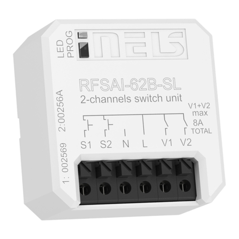
Elko iNels RFSAI-62B-SL quick start guide
FW Murphy
FW Murphy MLS Series Installation and operation manual
Maiwe
Maiwe MISCOM7028GX Series user manual
Allen-Bradley
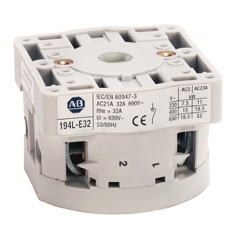
Allen-Bradley 194L installation instructions
Allied Telesis
Allied Telesis AT-FSW708 Specifications
