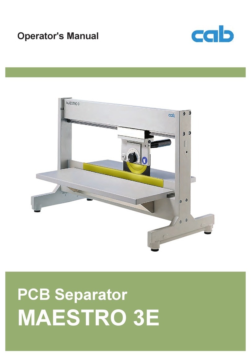
4.3 Upper Blade Adjustment
To avoid possible damage on the blades during
transport the upper blade (10) is fixed in the
"Park Position" so that there is a maximum
distance to the lower blade. Therefore the upper
blade has to be set into the working position
before switching on the machine :
1. There is a scale (8) on the frame where you
can see the height adjustment in steps of
1/10 mm.
When you receive the machine, the pointer
(9) of the scale is in position "16".
2. To adjust the upper blade loosen the knurled
knob (7) and hold the knob (6).
3. Rotate the knob (6) in a clockwise direction
until stop. Through that the upper blade(10)
move down to the lower blade (11) until both
blades are just touching one another (lower
end position). Make a notice of the position
of the pointer (9) to use it for all further
adjustments.
This lower end position locks the upper blade
in place to prevent it from moving out of
adjustment.
4. Move the knob (6) in the anti-clockwise
direction until the pointer is in the middle
position between the lower end position and
the position"16".
5. Tighten the knurled knob (7) and run some
test-cuts to check if it is possible to separate
the PCB's. If it is not possible reduce the
distance between the blades in small steps.
With it loosen always the knurled knob (7) an
the move the knob (6) in clockwise direction
to the requested position and then again tight
the knurled knob.
The described adjustment helps to reduce
the separation forces. This is important when
sensitive components are very close to the
groove
Important ! Before moving the machine to a
new location, set the upper blade to the Park
position.
4.3. Ajustage du couteau supérieur
Lors de la livraison du MAESTRO 2M, le
couteau supérieur (10) est réglé de telle sort
que l'écart entre les couteaux soit le plus grand
possible pour éviter toute dégradation des
couteaux pendant le transport.
C'est pourqoui, il est nécessaire de mettre le
couteau supérieur en position de travail pour
mettre la machine en route:
1. Sur le bâti, il y a une graduation (8) sur
laquelle la hauteur du couteau est lisible au
1/10ème. Lors de la livraison, l'aiguille (9) se
trouve sur «16».
2. Pour régler le couteau supérieur, dévisser
l'écrou (7) tout en maintenant la vis de
réglage (6).
3. Tourner la vis de réglage (6) dans le sens
des aiguilles d'une montre jusqu'à ce qu'elle
soit bloquée. Cela va déplacer le couteau
supérieur (10) vers le bas jusqu'à frôler le
couteau inférieur (11), position inférieur
maximum. Regarder sur la graduation (8) la
position indiquée par l'aiguille (9) et retenir
comme la position la plus basse pour les
réglages futurs.
La course permettant la descente du
couteau supérieur est ici limitée pour éviter
que les couteaux ne se touchent ou ne se
bloquent.
4. Tourner la vis de réglage (6) dans le sens
inverse des aiguilles d'une montre jusqu'à
mi-chemin entre la position inférieure
maximum (notée précédemment) et la
position d'attente «16».
5. Revisser l'ecrou (7) et vérifier en faisant un
test de séparation que les cartes sont bien
séparées.
Si cela n'est pas le cas, réduire l'écart entre
les couteaux petit à petit en refaisant les
opérations décrites précédemment: dévisser
l'écrou (7), tourner la vis de réglage (6) dans
le sens des aiguilles d'une montre, revisser
l'écrou (7).
Le mode d'ajustage décrit ci-dessus permet
de minimaliser les tensions mécaniques lors
de la séparation des cartes. Ceci est
particulièrement important quand des
composants sensibles se trouvent près de la
rainure.
Attention ! Lors de tout changement de place,
toujours remettre le couteau en position
d’attente.
7


