CAB MAESTRO 5L User manual

Operator's Manual
MAESTRO 5L
PCB Seperator

2 2
Description Type
PCB Separator MAESTRO 5L
Edition: 01/2012 - Part No. 9008464
Copyright
This documentation as well as translation hereof are property of cab Produkttechnik GmbH & Co. KG.
The replication, conversion, duplication or divulgement of the whole manual or parts of it for other intentions than its original
intended purpose demand the previous written authorization by cab.
Editor
Regarding questions or comments please contact cab Produkttechnik GmbH & Co. KG.
Topicality
Due to the constant further development of our products discrepancies between documentation and product can occur.
Please check www.cab.de for the latest update.
Terms and conditions
Deliveries and performances are effected under the General conditions of sale of cab. .
This Operator's Manual is delivered to the device:
Operator's Manual - Translation of the Original Version
for the following products
Germany
cab Produkttechnik
GmbH & Co KG
Postfach 1904
D-76007 Karlsruhe
Wilhelm-Schickard-Str. 14
D-76131 Karlsruhe
Telefon +49 721 6626-0
Telefax +49 721 6626-249
www.cab.de
France
cab technologies s.a.r.l.
F-67350 Niedermodern
Téléphone +33 388 722 501
www.cab.de
USA
cab Technology Inc.
Tyngsboro MA, 01879
Phone +1 978 649 0293
www.cabtechn.com
South Afrika
cab Technology (Pty.) Ltd.
2125 Randburg
Phone +27 11-886-3580
www.cab.de
Phone +86 21 6236-3161
2299 11C60
www.cabasia.net
cab (Shanghai) Trading Co.,Ltd
cab Technology Co, Ltd.
Junghe 23552, Taipei, Taiwan
Phone +886 2 8227 3966
Asia
Representatives in other countries on request.

2
3
Table of Contents
1 Introduction ............................................................................................................................................ 4
1.1 Instructions ............................................................................................................................................... 4
1.2 Intended Use ............................................................................................................................................ 4
1.3 Safety Instructions .................................................................................................................................... 4
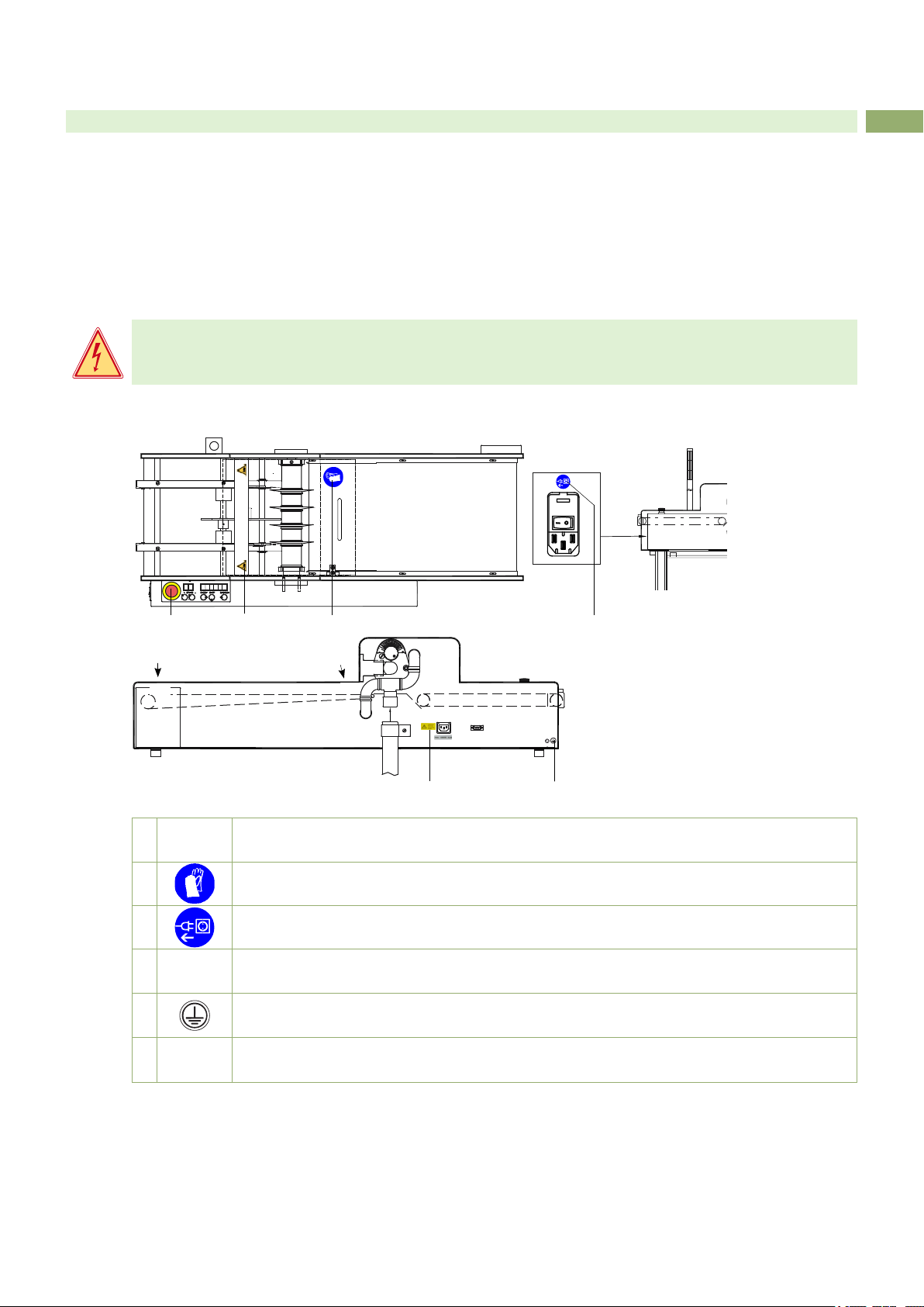
1.4 Safety Marking ......................................................................................................................................... 5
1.5 Environment ............................................................................................................................................. 5
2 Specication ........................................................................................................................................... 6
3 Installation .............................................................................................................................................. 7
3.1 Unpacking and Setting-up the Device ...................................................................................................... 7
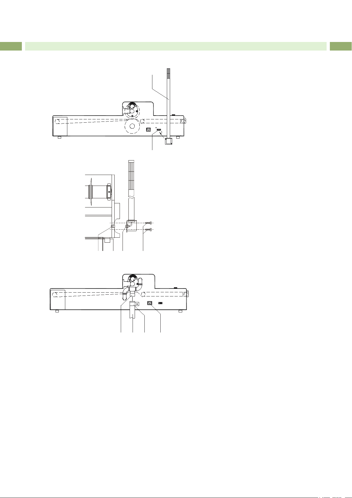
3.2 Mounting the device ................................................................................................................................. 8
3.3 Connections ............................................................................................................................................. 9
3.3.1 Earthing Connection ........................................................................................................................... 9
3.3.2 Power Supply ..................................................................................................................................... 9
3.3.3 Interfaces to a supply device / clear device ....................................................................................... 9
3.3.4 Connecting the Access Door Interlock................................................................................................ 9
3.3.5 Connecting of an Industrial Vacuum Cleaner ................................................................................... 10
4 Sensors ................................................................................................................................................. 11
4.1 General Function .....................................................................................................................................11
4.2 Extended Function ................................................................................................................................. 12
4.2.1. Coupling the MAESTRO 5L to a supply device (SMEMA interface) ................................................. 12
4.2.2. Coupling the MAESTRO 5L to the optional Conveyer Belt .............................................................. 12
5 Control Panel ........................................................................................................................................ 13
5.1 Control Panel ......................................................................................................................................... 13
5.2 Warning Light ......................................................................................................................................... 13
6 Programming ........................................................................................................................................ 14
7 Operation .............................................................................................................................................. 15
7.1 Switch On ............................................................................................................................................... 15
7.2 Self Test ................................................................................................................................................. 15
7.3 Speed Adjustment .................................................................................................................................. 15
7.4 Operation without external Conveyer Belt .............................................................................................. 16
7.5 Operation with external Conveyer Belt ................................................................................................... 17
7.6 Reverse Transport .................................................................................................................................. 17
8 Error Messages .................................................................................................................................... 18
9 Blade Replacement .............................................................................................................................. 19
9.1 Replacement of the Upper Blades ......................................................................................................... 19
9.2 Replacement of the Lower Blades ......................................................................................................... 21
9.3 Blade Adjustment ................................................................................................................................... 23
9.4 Adjustment of the Upper Guide .............................................................................................................. 24
9.5 Adjustment of the Supply Belts .............................................................................................................. 24
10 Interfaces .............................................................................................................................................. 25
11 Maintenance ......................................................................................................................................... 26
12 Spare Parts ........................................................................................................................................... 27
13 EC Declaration of Conformity ............................................................................................................. 29
14 Index ...................................................................................................................................................... 30

4 4
1 Introduction
1.1 Instructions
Important information and instructions in this documentation are designated as follows:
Danger!
Draws your attention to an exceptionally grave, impending danger to your health or life.
!
Warning!
Indicates a hazardous situation that could lead to injuries or material damage.
!
Attention!
Draws attention to possible dangers, material damage or loss of quality.
i
Notice!
Gives you tips. They make a working sequence easier or draw attention to important working processes.
Environment!
Gives you tips on protecting the environment.
Handling instruction
Reference to section, position, illustration number or document.
Option (accessories, peripheral equipment, special ttings).
1.2 Intended Use
• The device is manufactured in accordance with the current technological status and the recognized safety rules.
However, danger to the life and limb of the user or third parties and/or damage to the device and other tangible
assets can arise during use.
• The device may only be used for its intended purpose and if it is in perfect working order, and it must be used with
regard to safety and dangers as stated in the operating manual.
• The device is intended exclusively for separating pre-scored PCB's. Any other use or use going beyond this
shall be regarded as improper use. The manufacturer/supplier shall not be liable for damage resulting from
unauthorized use; the user shall bear the risk alone.
• Usage for the intended purpose also includes complying with the operating manual, including the manufacturer‘s
maintenance recommendations and specications.
i
Notice!
The complete documentation can also currently be found in the Internet.
1.3 Safety Instructions
• The device is congured for voltages of 115 or 230 V AC. It only has to be plugged into a grounded socket.
• Hazard by electrical charge. Provide an earthing connection via press stud.
• Only connect the device to other devices which have a protective low voltage.
• Switch off all affected devices (e.g. conveyor belt) before connecting or disconnecting.
• Risk of hand injury. Wear protective gloves while PCB separating.
• Ensure that people‘s clothing, hair, jewelry etc. do not come into contact with the exposed rotating blade.
• In an emergency situation, actuate the emergency stop switch in the control panel by tight pressing. This inter-
rupts the voltage supply to the device.
• The device may only be used in a dry environment, do not expose it to moisture (sprays of water, mists, etc.).
• Do not use the device in an explosive atmosphere.

4
5
1 Introduction
• Do not use the device close to high-voltage power lines.
• Work going beyond this may only be performed by trained personnel or service technicians.
• Unauthorized interference with electronic modules or their software can cause malfunctions.
• Other unauthorized work on or modications to the device can also endanger operational safety.
• Always have service work done in a qualied workshop, where the personnel have the technical knowledge and
tools required to do the necessary work.
• There are various warning stickers on the device. They draw your attention to dangers.
Warning stickers must therefore not be removed, as then you and other people cannot be aware of dangers and
may be injured.
Danger!
Danger to life and limb from power supply.
Do not open the device casing.
1.4 Safety Marking
Fig. 1 Safety marking
1Risk of hand injury !
Wear protective gloves while PCB separating.
2Risk of hand injury !
Wear protective gloves while PCB separating.
3Possible damage of electronics !
Disconnect the PCB separator from electrical outlet before mounting an optional device.
4Danger to life and limb from power supply.
Be carefully in work with metallic equipment near electrical outlet!
5Hazard by electrical charge !
Provide an earthing connection via press stud.
6Attention! Laser light!
Save your eyes, don't look into the light!
Table 1 Safety marking
1.5 Environment
Obsolete devices contain valuable recyclable materials that should be sent for recycling.
Send to suitable collection points, separately from residual waste.
The modular construction of the printer enables it to be easily disassembled into its component parts.
Send the parts for recycling.
23
1
45
66
Emergency Switch

6 6
The PCB Separator is designed for cases of application, with which scratched PCBs must be separated. For the
commercially viable assembly and mounting of printed circuit boards, there is an ever increasing requirement for
multiple-use material. The necessity however, to break off sections of the circuit board by hand can cause damage to
the delicate circuitry and components. The bre-glass material tears at the broken edge, leaving it rough and ssured.
Using the MAESTRO 5L to cleanly and economically separated pre-scored PCB’s.
The PCB moved by a belt into the cutting area. By rotating circular blades it will cut and transported automatically.
After this, the separated PCB's will transported by a belt an it's possible to take it by hand.
Special steel blades give a guaranty for a long operation time.
A
A
B
B
C
C
30° 30°
Figure 2 Measurements of the device
2 Specication

6
7
2 Specication
3 Installation
3.1 Unpacking and Setting-up the Device
Unpack the device.
Check the device for damages which may have occurred during transport..
Set up the device on a even surface.
Check delivery for completeness.
Contents of delivery:
• PCB Separator
• Power Cable
• Warning Light with 2 Screws for mounting
• Chassis with 4 Cylinder Head Screws M6x16 with Washers
• 2 Handles (for changing Blades
• Device (for changing the Blades)
• Open-end Wrench SW 41
• Spanner Wrench
• Documentation
i
Notice
Please keep the original packaging in case the device must be returned.
!
Attention!
The device and printing materials will be damaged by moisture and wetness.
Set up the device only in on dry locations, protected from splash water.
Separation length in mm 100 - 600
Weight in kg 71
Separation principle upper and lower circular blades
PCB thickness A in mm 1 - 3,2
Thickness of remaining material B in mm A/3, min. 0,3, max. 0,6
Score depth C in mm > 0,3
Increase of external dimensions
following separation in mm
0,1 - 0,2
Separation speed in mm/s 100-220
Component height
in mm
component side
solder side
max. 30
max. 10
Power supply 230/115 V~ - 50/60 Hz
Protection class 1 Protection Class IP 20
Operating temperature 10 - 35 °C
Storage/transport temp. -20 - +50 °C
Humidity 10 - 85%, non-condensing
Maximum Sound Pressure Level LpA < 70 dB(A)
Emergency switch
Table 2 Technical Data

8 8
3.2 Mounting the device
The MAESTRO 5L is shipped with the warning light (1)
disconnected.
1. Plug the 9 pin SUB-D-connector (10) located on the
bottom of the warning light (1) into the socket (9) on
the back of the MAESTRO 5L.
2. Attach the warning light with the supplied M5x12
screws (2).
Figure 3 Mounting the Warning Light
3. When ordering the MAESTRO 5L with the indus-
trial vacuum option the vacuum connection (1) is
mounted at the factory.
4. A tube adapter (2) is shipped with the MAESTRO 5L.
The size of the tube adapter varies, depending on
the vacuum to be used with the separator. The tube
adapter is connected to the vacuum cleaner on one
end and connected to the vacuum connection (1) at
the other end, using the supplied tube clamp (3).
5. To connect the power to the vacuum, connect the
supplied power adapter cable to the power socket
(4) located at the rear of the MAESTRO 5L. Then
plug the vacuum into the power adapter cable.
6. Switch the vacuum into the ON position. It will not
start until the main drive of the MAESTRO 5L is
turned on.
7. When the main drive is turned off, the vacuum will be
turned off.
Figure 4 Mounting the Industrial Vacuum Cleaner
3 Installation
1
2
32 1
4321

8
9
3 Installation
3.3 Connections
3.3.1 Earthing Connection
!
Attention!
Hazard by electrical charge !
Provide an earthing connection via press stud
3.3.2 Power Supply
Figure 5 Power Supply
1. Ensure that the device is switched off at the power switch (3).
2. Check the setting of the voltage selector (1).
• In order to alter the setting open the ap (2) at the power input module.
• Remove the voltage selector and re-insert it so that the correct voltage is visible when module the ap is closed.
• Upon altering the setting, the fuses in the module must also be changed accordingly (T800 mA for 230 V; T1,6 A
for 115 V).
3. Connect the power cable to the power input module (4) and to an earthed socket.
4. If the machine does not show any function after it has been switched on, please check the fuses of the mains
module and the fuse (T4A) of the electronics board.
3.3.3 Interfaces to a supply device / clear device
(Forerunner / Follower)
The two 14-pin socket for the SMEMA-interfaces (1/2), to couple supply devices, are mounted on the underside of
the front cover, on the left side of the MAESTRO 5L.
Connect the interface cable of the supply device with this socket.
i
Notice
For the use of other interface protocols slight modications of the hardware are necessary !
Figure 6 SMEMA-interface and cover contact
3.3.4 Connecting the Access Door Interlock
The access door contact switch plug (6) must be plugged into the 5-pin diode socket (7) located on the under side of
the MAESTRO 5L. The socket can be seen from inside the chassis access door.
1
2
3
4
1 2
3 4 5

10 10
3 Installation
3.3.5 Connecting of an Industrial Vacuum Cleaner
Figure 7 Connecting of an Industrial Vacuum Cleaner
Connect the supplied adapter cable to the power socket (1) on the back of the MAESTRO 5L.
Switching the vacuum ON and OFF is controlled via the software in the separator.
!
Attention!
Maximum charging rate is 6.5 amp !
1

10
11
4 Sensors
4.1 General Function
Figure 8 Sensors
The MAESTRO 5L is equipped with a number of sensors which control the travel of the PCB through the separator.
Sensor 1 (3)
The reective sensor is coupled with a clock wheel which is mounted at a supply belt (1). The reective sensor is
necessary to measure the length of cut.
Sensor 2 (4)
This laser edge sensor is mounted directly in front of the blades. This is necessary to sense the leading edge and
trailing edge of the PCB.
By exceeding a limiting value between sensing the leading edge and the trailing edge of the PCB, the operator gets
an error.
This sensor may also be used to count the number of separated panels.
Sensor 3 (5)
his laser edge sensor is mounted directly behind the blades.
This sensor controls the leading edge and trailing edge of the PCB in a time distance to sensor 2.
By exceeding the time tolerances to sensor 2 the operator gets an error message (leading edge to trailing edge
respectively late to sensor 3)..
Sensor 4 (6)
This laser edge sensor is mounted directly at the end of the conveyer belt (2). When a PCB with components is
sensed it stops the material supply. Edge strips without components are not sensed by this sensor.
4 5
1 2
63

12 12
4 Sensors
4.2 Extended Function
Figure 9 Sensors
The integration of the MAESTRO 5L into a PCB production line will extend the function of the sensors. The interface
signals will be controlled by interpreting the sensor signals. The interface signals report the readiness of the separator
to receive and deliver PCBs respectively to adjacent devices.
4.2.1. Coupling the MAESTRO 5L to a supply device (SMEMA interface)
Sensor 2 (4)
When a penalized PCB from a supply device arrives at the sensor, the SMEMA signal for the takeover readiness will
be switched off and a 20 second timer is then started.
After the 20 second timer, the MAESTRO 5L will be in the takeover readiness mode again unless the sensor is inter-
rupted (by a PCB).
In this case an error 5 message will occur.
The sensor 2 also checks to see whether or not a PCB arrives at the sensor 20 seconds after seeing the prior PCB.
In the event a new PCB is not supplied to the separator and therefore not detected by the sensor, the yellow warning
light will be switched on.
Sensors 3 and 4 (5/6)
The SMEMA signal for the takeover readiness will be switched on if a panel from a supply device leaves sensor 3 and
sensor 4 is not active (see programming section).
A timer will be started when a panel from a supply device leaves sensor 3 and sensor 4 is active (see programming).
After the 20 seconds, the switch state of sensor 4 will be checked. The SMEMA signal for takeover readiness will be
switched on if sensor 4 is free.
4.2.2. Coupling the MAESTRO 5L to the optional Conveyer Belt
Sensor 4 (6) / Conveyer belt sensor (7)
At the end of the optional conveyer belt is another laser edge sensor (7). If this sensor is free, the conveyer belt will
be started for a dened period of time after a panel is detected at sensor 4 (6). When a second panel is detected at
sensor 4 (6) the time will be extended.
The conveyer belt stops when a PCB is sensed by the conveyer belt sensor (7). When the conveyer belt stops, the
MAESTRO 5L receives a signal that informs that the conveyer belt is not ready to take over more PCBs. At this point,
the main drive of the separator will be stopped when a PCB arrives at sensor 4 (6).
4 5
1 2
6
3
67

12
13
5 Control Panel
5.1 Control Panel
Figure 10 Control panel
At the control panel of the MAESTRO 5L are ve user keys, two displays and one emergency switch.
These have the following functions under normal conditions.
Emergency Switch
!
Warning!
In case of emergency, an emergency stop switch (4) has been provided. Activate the emergency switch by
pressing it rmly. This interrupts the voltage supply to the MAESTRO 5L.
The switch is deactivated by turning the red button in either direction. To start the machine again, perform the normal
start procedure.
Displays
Two digit : indicates the working speed
Six digit : indicates the length of cuts or the number of separated panels.
Display 2 : indicates one point, if a PCB reaches sensor 4, until it leaves it again
Display 3 : indicates one point, if a PCB reaches sensor 5, until it leaves it
Display 4 : indicates one point, if a PCB reaches sensor 6, until it leaves it again
User Keys
SPEED+ : increases the working speed (100-220 mm/s in 10 increments)
SPEED- : decreases the working speed
START : switches on the main drive
STOP : switches off the main drive
REVERSE : reverses the main drive (as long as key is depressed; REVERSE can only be used
in STOP- or error-mode)
The LED's in the keys represent which keys are available in the respective operation mode.
5.2 Warning Light
Depending on the operation mode, the following lamps of
the warning light (1) will be switched on
red:
yellow:
green:
The MAESTRO 5L is in the error mode.
The MAESTRO 5L is ready to receive a PCB,
but has not received one in 20 seconds.
An error at the supply device is a possible
cause.
The power supply of the MAESTRO 5L is in
the ON position.
Figure 11 Warning light
1 2 3 4
1

14 14
6 Programming
Figure 12 Control panel
To put the MAESTRO 5L into the programming mode, press the START and STOP keys at the same time.
The six digit display shows the parameter which can be changed and the two digit display shows the actual setting.
PA 1 : Activation of the keys SPEED+ and SPEED-
0 = inactive, 1 = active
PA 2 : Interpretation of sensor 2 and 3 for jam detection
0 = inactive, 1 = active
PA 3 : Interpretation of sensor 4
To switch off the transport of PCBs into the MAESTRO 5L
0 = inactive, 1 = active
PA 4 : Change the 6 digit display
0 = to display total length of cuts
1 = to display the number of panels separated
PA 5 : Restart mode after stopping material transport via sensor 4 (conveyer belt end).
0 = restart by pressing the START key after removing the material from sensor 4
1 = restart automatically when the material is removed from sensor 4
PA 6 and PA 7: Connection of a following device
PA 6 PA 7
0 0 No device
0 1 Device connected via SMEMA interface
1 0 Device connected via cab-specic interface
1 1 not allowed
!
Attention!
By activating PA 6 or PA 7, PA 3 is set to zero internally !
PA 8 : This parameter will be set on "0" !
Use SPEED+ key to toggle between "0" and "1".
Use the START key to toggle to the next parameter.
After PA 8, press the START key to enter the normal operation mode.
i
Notice
The counter display can be reset by pressing the SPEED+ and SPEED- keys simultaneously.

14
15
7 Operation
Figure 13 Control panel
7.1 Switch On
Switch on the MAESTRO 5L at the power switch.
The displays show the actual values of the working speed and the total number of cuts or length of cuts respectively.
The green lamp of the warning light blinks.
Check the following if the displays do not light up:
• The power supply setting is correct.
• The fuses in the power supply are intact.
7.2 Self Test
After switching the machine on, the LED in the START key blinks. Press the START key. The LED goes out and the
MAESTRO 5L carries out a self test. In this case, the main drive will be turned on for 10 seconds.
During the self test the green lamp of the warning light blinks.
Upon successful completion of the self test, the machine will go into the normal working mode. The green lamp of the
warning light shines.
In the event the test fails, the START key will blink again.
The green lamp of the warning light blinks and the red lamp shines.
Check the device for any possible pieces of PCB caught in the unit. If so remove them and start the test again.
In the event normal operation is interrupted by pressing the STOP key or REVERSE key, or an error occurs. The
machine will perform another self test before normal operation can be achieved.
7.3 Speed Adjustment
The working speed of the MAESTRO 5L may be varied by pressing the SPEED+ key or SPEED- key. This can be
done in the standby mode or during normal operation.
The function of these keys can be turned off in the programming mode.

16 16
7 Operation
7.4 Operation without external Conveyer Belt
Figure 14 Operation without external Conveyer Belt
!
Warning!
In case of emergency, an emergency stop switch (4) has been provided. Activate the emergency switch by
pressing it rmly. This interrupts the voltage supply to the MAESTRO 5L.
After successfully completing the self test, place the PCB (1) on the supply belts (2), either manually or via a
supply device.
!
Attention!
Make sure the pre-scored groove of the PCB is set on the guide (5) and is lead by the upper guide (6)!
The PCB is transported into the cut zone, grasped by the circular blades (3), and separated into individual pieces.
The separated PCBs and edge strips are transported away from the cut zone via an internal conveyer belt.
The PCBs may then be taken away for further operations.
At the end of the conveyer is a sensor (sensor 4). This sensor can be programed (PA 3 =1) to stop when the PCBs
are not removed from the conveyer. The restart is adjusted by the parameter PA 5.
This can be set to start immediately after removing the PCBs from the sensor, or by pressing the START key. The
sensor height is adjusted so that edge strips will not stop the belt and can be transported to a collecting box.
The normal operation mode can be interrupted by pressing the STOP key on the control panel. Before the machine
can be restarted, a self test must be performed.
Opening the bonnet over the cut zone shuts down the main drive and shuts down the whole system.
Once the bonnet is closed, the machine can be restarted after completing the self test.
1 2 3
654

16
17
7 Operation
7.5 Operation with external Conveyer Belt
Figure 15 Operation with external Conveyer Belt
In operation of the MAESTRO 5L with an external conveyer belt by cab (Option) are the most items identical like 7.
But see follow differences :
• The conveyer belt has an own power supply. The motor of the conveyer belt is controlled via the interface with the
MAESTRO 5L.
• The conveyer belt is switched on when a PCB arrives at sensor 4 (7) of the MAESTRO 5L.
• The laser light edge sensor (9), located at the end of the conveyer belt, stops the belt when a PCB is sensed and
eventually stops the material transport in the separator when a PCB is sensed at sensor 4 (7).
The process is restarted when the PCB is removed from the laser edge sensor at the end of the conveyer (9).
• For the conveyer belt to run continuously, PCBs with components must be removed before arriving at the
conveyer belt sensor (9) and the MAESTRO 5L must deliver following PCBs in a dened period of time.
• The operation of the conveyer belt can be interrupted and restarted by pressing the pause key (8).
• In order to restart, the sensor (9) must be uninterrupted.
7.6 Reverse Transport
If an error occurs or the STOP key is pressed during
operation, and it is necessary to remove a PCB from the
cut zone, the material can be transported backward.
Press the REVERSE key.
In this case, the circular blades (3) and the supply
belts (2) will be reversed as long as the key is
pressed.
Figure 16 Reverse Transport
1 2 3
1 2 3
654

18 18
When an error occurs, the red lamp of the warning light will be switched on. The six digit display will indicate the
specic error.
ERROR 1 :
• The bonnet cover over the cut zone is open.
Close the bonnet cover and press the START key.
• The connector of the chassis door contact, is not connected to the diode socket of the MAESTRO 5L.
Make the connection and press the START key.
• The drive is jammed with PCB material.
Remove the material and press the START key.
• Drive is defective.
Call for service.
ERROR 2 :
• The front edge of the PCB does not arrive at sensor 3 in the dened time after being sensed by sensor 2 (jam).
Remove the jam
Press the START key.
ERROR 3 :
• The rear edge of the PCB does not arrive at sensor 3 in the dened time after being sensed by sensor 2 (jam).
Remove the jam
Press the START key.
ERROR 4 :
• The rear edge of the PCB does not arrive at sensor 2 in the dened time relative to sensing the front edge (jam).
Remove the jam
Press the 'START key
ERROR 5 :
• The MAESTRO 5L does not enter the takeover readiness mode for receiving a new PCB in the dened 20
seconds after receiving the previous PCB.
i
Notice
Error messages ERROR 2, ERROR 3 and ERROR 4 can be disabled by changing the
program parameter PA 2.
This is recommended by separating even PCBs that means by using thin PCB material or by using small
components.
There the sensors do not recognize the PCBs.
ERROR 6 :
• Sensor 1 recognizes material during self test.
Remove the material
Press the REVERSE key.
ERROR 7 :
• Sensor 2 or 3 recognizes material after nishing the self test.
Remove the material
Press the START key or the REVERSE key.
ERROR 8 :
• Sensor 4 recognizes material during self test.
Remove the material
Press the START key or the REVERSE key.
i
Notice
Error messages ERROR 6, ERROR 7 and ERROR 8 are valid during the self test.
8 Error Messages

18
19
9 Blade Replacement
9.1 Replacement of the Upper Blades
13 13
14
Figure 17 Replacement of the Upper Blades
Danger!
Unplug the power source to the MAESTRO 5L before working on it !
!
Warning!
Risk of hand injury !
When handling the blades, protective gloves should be worn !
1. Remove the bonnet by swinging it up 90° and lifting it out of the slots in the side panels.
2. Loosen screws (2) to remove cover plates (1) .
3. Move the upper blades (3) into the uppermost position.
The position of the upper blades can be read on the scales (5) located on each of the adjustable anges (7). The
scales are in 1/100 mm increments.
In the uppermost position the pointer (6) points to position ''16''.
4. Loosen the cylinder screws (4) on the adjustable anges (7).
5. Rotate the adjustment knobs (8) in the counterclockwise direction until the position ''16'' is reached.
6. Tighten the cylinder screws (4).
7. Screw the handles (13), included with the unit, into the ends of the upper blade shaft (9).
8. Remove the retaining anges (10) by removing the cylinder screws (11).
9. Loosen the rear anges via the cylinder screws (12) as needed to remove the complete blade shaft (9) from the
machine.
Place the blade shaft on the console (14) provided.
10. Remove the handles (13) from the shaft.
3 4 65
3
11 10 12
7 8
11109
1 2
1
2

20 20
Figure 18 Blade Replacement
11. Place the blade shaft into the provided device (16).
Loosen the spanner nut (14) with the spanner wrench provided, while holding the open-end wrench (41mm) on
area (14).
!
Attention!
Do not manipulate the second spanner nut (15) at this time !
12. Remove the circular blades (5) and spacers (19) from the blade shaft.
Keep the spacers in the order they were removed.
13. Slide the replacement blades (5), with the appropriate spacers (19) onto the shaft.
14. Mount the spanner nut (16) and tighten it.
15. Put the blade shaft back into the machine using the handles (13).
Slide the shaft into the adjustable anges as far as possible.
16. Remount the retaining anges (10) using the cylinder screws (11).
Tighten it easy.
17. Tighten the cylinder screws (12) on the rear anges rst, and then tighten the cylinder screws (11) at the retaining
anges.
18. Adjust upper and lower blades.
19. Remount the cover and restore the connections.
20. Mount cover plates (1) again and tighten it with screws (2).
9 Blade Replacement
15
16
17
18
19 3
18
Table of contents
Other CAB Water Filtration System manuals
Popular Water Filtration System manuals by other brands

Watts
Watts pure H2O H2O-FK101 Installation, operation and maintenance manual

VistaPure
VistaPure V3000 Installation guide & owner's manual

Philips
Philips WP3870 user manual

Culligan
Culligan WH-S100-O Installation and operation instructions

Watts
Watts GTS450S Installation, operation & maintenance manual

Perma Pure
Perma Pure Baldwin series instruction manual