CAB MAESTRO 2 User manual

MAESTRO 2
Art.-Nr. 8933900
Bedienungs- und Serviceanleitung
Instructions for Use and Service
Manuel d'utilisation et de service
Ausgabe / Edition 3/07

2
1. Technische Daten
Gestell Aluminiumguß
Messer / Führungen gehärtet und geschliffen
Erdung Druckknopf ø 10 mm
Trennlänge bis 300mm
Leiterplattendicke A 0,8 bis 3,2 mm
Vergrößerung der Außenmaße
nach dem Trennen 0,1 bis 0,2 mm
Empfohlene Restdicke B 1/3 von Maß A
min. 0,25 mm, max. 0,8 mm
Ritztiefe C min. 0,25 mm
Betriebstemperatur 10 bis 35°C
Lager- und Transporttemperatur -20 bis 50°C
Luftfeuchte 10 bis 85% nicht kondensierend
Sicherheitsbestimmungen nach DIN 31001
und DIN EN 294
GS und CE-Zeichen erteilt
UL-Normen werden eingehalten
Gewicht 16 kg
Mit dem Nutzentrenner MAESTRO 2 werden
vorgeritzte Leiterplatten schonend und wirt-
schaftlich getrennt. MAESTRO 2 arbeitet ohne
Strom und Druckluft. Er ist an jedem Arbeitsplatz
sofort einsatzbereit.
Die Einstellung der Schneidemesser sowie der
Führungen wird einfach und schnell erledigt.
Verschleißfeste Messer und Führungen aus
Spezialstahl sichern lange Standzeit ohne
Nacharbeit.
Die Messer und Führungen stehen rechtwinklig
zur Leiterplatte, damit Bauteile bis 40 mm Höhe
bis an die Kante der Ritznut bestückt werden
können.
Ob dünne oder dicke Leiterplatten, MAESTRO 2
trennt alle leicht und schonend.

3
1. Caractéristiques techniques
Chassis fonderie d'aluminium
Couteaux/Guides affûtés et durcis
Mis à la terre pression de 10 mm
Longueur de coupe jusqu'à 300mm
Epaisseur des cartes A 0,8 - 3,2 mm
Tolérance à prevoir lors
du design des cartes 0,1 à 0,2 mm
Epaisseur résiduelle conseillée B
1/3 de la valeur A
min. 0,25mm, max. 0,8mm
Epaisseur de rainure C min. 0,25mm
Température d'utilisation 10 à 35°C
Température de stockage
et de transport -20 à +50°C
Humidité 10 à 85% HR
Dispositifs de sècurité selon DIN 31001
et DIN EN 294
Certicat GS et CE
Normes UL respectées
Poids 16 kg
By using the MAESTRO 2 PCB Separator,
pre-scored PCB's are cleanly and economically
separated.
The MAESTRO 2 requires neither electricity nor
compressed air, and can therefore be used im-
mediately, wherever and whenever required.
Adjustment of the guides can be quickly and
easily carried out.
Wear resistant blades and guides made from
special steel ensure a long working life without
adjustment. It does not matter whether the
PCB's are thick or thin, the extremely robust and
stable MAESTRO 2 separates them gently and
easily.
1. Technical Data
Frame Cast Aluminium
Blades and Guide Hardened and Polished HSS
Earthing Press-stud 10 mm. dia.
Separation length up to 300mm.
PCB Thickness A 0,8 - 3,2 mm.
Increase in External Dimensions
Following Separation 0,1 - 0,2 mm.
Thickness of Material Remaining B
after pre-scoring 1/3 from measure A
min. 0.25mm, max. 0.8mm
Depth of the Slot C min. 0,25mm
Operational Temperature 10 - 35°C.
Storage / Transport Temperature -20 - +50°C.
Humidity 10 - 85% non condensing
Safety Standards acc. to DIN 31001
and DIN EN 294
Certicate GS and CE
UL-Norms are conformed to
Weight 16 kg. (35 lbs.)
Le séparateur de cartes MAESTRO 2 coupe
soigneusement et à peu de frais les cartes pré-
rainurées.
MAESTRO 2 fonctionne sans courant et sans air
comprimé. Il peut être installé rapidement à tout
poste de travail.
Les couteaux et les guides en acier spécial sont
affûtés pour assurer une utilisation optimale et
durable. Le réglage des guides se fait aisément
et rapidement.
La coupe sera toujours propre quelle que soit
l'épaisseur des cartes à séparer.

4
2. Lieferumfang
Nutzentrenner MAESTRO 2
Bedienungsanleitung
Innensechskantschlüssel 2mm
3. Sicherheitshinweise
ACHTUNG !
Das Gerät ist ausschließlich zum Trennen
vorgeritzter Leiterplatten zu benutzen. Jede
andere Verwendung des Gerätes ist unzu-
lässig !
Eingriffe am Gerät, die über die in dieser
Bedienungsanleitung beschriebenen Hand-
lungen hinausgehen, sind nur von autorisier-
tem Personal durchzuführen.
Beim Trennen der Leiterplatten sind Schutz-
handschuhe zu tragen.
Während des Betriebs ist darauf zu achten,
daß Schmuckstücke, lose Kleidung, Haare
u.ä. aus dem Bereich der rotierenden Messer
ferngehalten werden.
4. Aufstellung und Inbetriebnahme
Der Nutzentrenner MAESTRO 2 ist nach der
Aufstellung auf einer ebenen Unterlage (1) mit
wenigen Handgriffen einsatzbereit.
Bei der Erstinbetriebnahme ist es günstig, die
Messer mit einem weichen Tuch zu entfetten.
4.1. Erdanschluss herstellen
Am Gerät ist ein Druckknopf mit dem Durchmes-
ser 10 mm (2) angebracht.
Die Herstellung des Erdanschlusses ist notwen-
dig, da es beim Trennen von Leiterplatten zu
elektrostatischen Auadungen kommen kann.
•
•
•
•
•
•
•
2 1

5
2. Détail fourniture
Séparateur de cartes pré-rainurées
MAESTRO 2
Mode d’emploi
Clé hexagonale de 2mm
3. Conseils de sécurité
ATTENTION !
L’appareil est exclusivement fait pour séparer
les cartes pré-rainurées.
Toute autre utilisation de la machine est
déconseillé.
Seules les personnes autorisées peuvent
utiliser, ajuster ou réparer la machine,
conformément aux conseils donnés ci-après.
Toujours porter des gants de protection lors
de la séparation des cartes
Pendant l’utilisation, toujours prendre garde
aux bijoux, aux vêtements, aux cheveux etc.
qui risqueraient de se prendre dans les
couteaux.
4. Installation et mise en route
L’installation du MAESTRO 2 se fait selon les
indications qui suivent et peu de manipulations
sont nécessaires.
Lors de la première mise en route il est recom-
mandé de retirer la graisse qui se trouve sur les
couteaux à l’aide d’un chiffon doux.
4.1. Mise à la terre
Ceci est impératif pour éviter les charges élec-
trostatiques !
L’appareil est équipé d'un branchement :
ø10 mm (2).
•
•
•
•
•
•
•
2. Contents of Delivery
MAESTRO 2 PCB Separator
Instructions for Use
Allen Key 2mm
3. Safety Precautions
CAUTION !
The machine may only be used to separate
pre-scored PCB’s.
Use for any other purpose is not allowed !
Any adjustments or repairs which are not
described in these instructions may only be
carried out by authorised personnel.
When separating PCB’s, protective gloves
must be worn.
During operation, ensure that all loose, hang-
ing items eg. Jewelry, Clothing, Hair etc., are
kept well clear of the rotating blades.
4. Setting Up and Putting Into
Operation
When the MAESTRO 2 PCB Separator is
placed on a rm surface (1), it can then be put
into operation with the minimum of effort.
When using the machine for the rst time, it is
advisable to wipe both blades clean of the pro-
tective oil lm by using a soft cloth.
4.1. Establish ground contact
Mounted at the rear of the machine is a
press-stud, 10mm.(2). Earthing is necessary due
to the possibility of electrostatic charges building
up when PCB’s are cut.
•
•
•
•
•
•
•

6
4.2. Justage Obermesser
Das Obermesser (7) ist bei Lieferung des
MAESTRO 2 so eingestellt, daß sich der
größtmögliche Abstand zum Untermesser (8)
ergibt (Parkposition), um eventuellen Transport-
schäden an den Messern vorzubeugen. Daher
ist das Obermesser bei der Inbetriebnahme des
Gerätes in die Arbeitsposition zu stellen :
Am Gestell ist eine Skala (5) angebracht, an
der die Höheneinstellung des Messers in
1/10mm ablesbar ist. Bei Lieferung steht der
Zeiger (6) in Stellung "16".
Lösen Sie zur Verstellung des Obermessers
die Rändelmutter (4). Halten Sie dabei den
Einstellknopf (3) fest.
Drehen Sie den Einstellknopf (3) bis zum
Anschlag im Uhrzeigersinn. Dadurch wird das
Obermesser (7) soweit nach unten bewegt,
daß es das Untermesser (8) minimal berührt
(untere Endposition). Halten Sie die erreichte
Stellung des Zeigers (6) als Ausgangsstellung
für weitere Justagen fest.
Der Verstellweg des Obermessers ist hier
begrenzt, um ein Übereinanderfahren der
Messer zu verhindern.
Drehen Sie den Einstellknopf (3) entgegen
dem Uhrzeigersinn etwa bis zur Mitte zwi-
schen unterer Endstellung und Stellung "16".
Ziehen Sie die Rändelmutter (4) an und
überprüfen Sie mit Testschnitten, ob sich
die Leiterplatten vollständig trennen lassen.
Wenn dies nicht der Fall ist, verringern Sie
den Messerabstand in kleinen Schritten.
Lösen Sie dazu wiederum die Rändelmutter
(4), drehen Sie den Einstellknopf nach Bedarf
im Uhrzeigersinn und ziehen Sie die Rändel-
mutter wieder an.
Die beschriebene Justagemethode ermöglicht
eine Minimierung der mechanischen Span-
nungen beim Trennen der Leiterplatten. Dies
ist besonders wichtig, wenn sich empndliche
Bauelemente in unmittelbarer Nähe der Ritznut
benden.
ACHTUNG !
Bei einem Standortwechsel ist das
Obermesser wieder in die Parkpositi-
on zu stellen.
1.
2.
3.
4.
5.
4
5 6
3 7 8
3

7
4.2. Upper Blade Adjustment
To avoid possible damage on the blades during
transport the upper blade (7) is xed in the "Park
Position" so that there is a maximum distance to
the lower blade. Therefore the upper blade has
to be set into the working position before switch-
ing on the machine :
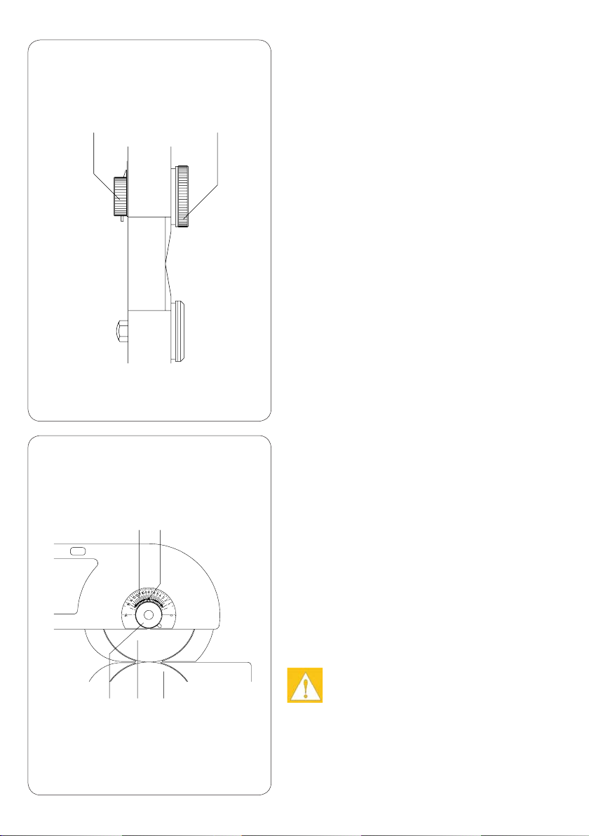
There is a scale (5) on the frame where you
can see the height adjustment in steps of
1/10 mm.
When you receive the machine, the pointer
(6) of the scale is in position "16".
To adjust the upper blade loosen the knurled
knob (4) and hold the knob (3).
Rotate the knob (3) in a clockwise direction
until stop. Through that the upper blade (7)
move down to the lower blade (8) until both
blades are just touching one another (lower
end position). Make a notice of the position of
the pointer (6) to use it for all further adjust-
ments.
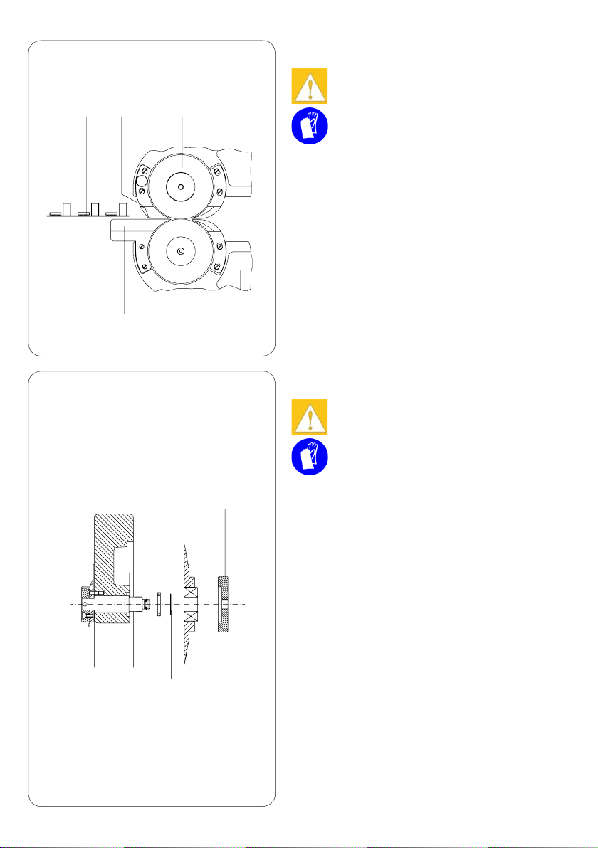
This lower end position locks the upper blade
in place to prevent it from moving out of
adjustment.
Move the knob (3) in the anti-clockwise
direction until the pointer is in the middle posi-
tion between the lower end position and the
position "16".
Tighten the knurled knob (4) and run some
test-cuts to check if it is possible to separate
the PCB's. If it is not possible reduce the
distance between the blades in small steps.
With it loosen always the knurled knob (4) an
the move the knob (3) in clockwise direction
to the requested position and then again tight
the knurled knob.
The described adjustment helps to reduce the
separation forces. This is important when sensi-
tive components are very close to the groove
CAUTION !
Before moving the machine to a new
location, set the upper blade to the
Park position.
1.
2.
3.
4.
5.
4.2. Ajustage du couteau supérieur
Lors de la livraison du MAESTRO 2, le couteau
supérieur (7) est réglé de telle sort que l'écart
entre les couteaux soit le plus grand possible
pour éviter toute dégradation des couteaux
pendant le transport.
C'est pourquoi, il est nécessaire de mettre le
couteau supérieur en position de travail pour
mettre la machine en route:
Sur le bâti, il y a une graduation (5) sur
laquelle la hauteur du couteau est lisible au
1/10ème. Lors de la livraison, l'aiguille (6) se
trouve sur «16».
Pour régler le couteau supérieur, dévisser
l'écrou (4) tout en maintenant la vis de
réglage (3).
Tourner la vis de réglage (3) dans le sens des
aiguilles d'une montre jusqu'à ce qu'elle soit
bloquée. Cela va déplacer le couteau supé-
rieur (7) vers le bas jusqu'à frôler le couteau
inférieur (8), position inférieur maximum.
Regarder sur la graduation (5) la position
indiquée par l'aiguille (8) et retenir comme
la position la plus basse pour les réglages
futurs.
La course permettant la descente du couteau
supérieur est ici limitée pour éviter que les
couteaux ne se touchent ou ne se bloquent.
Tourner la vis de réglage (3) dans le sens
inverse des aiguilles d'une montre jusqu'à mi-
chemin entre la position inférieure maximum
(notée précédemment) et la position d'attente
«16».
Revisser l'écrou (4) et vérier en faisant un
test de séparation que les cartes sont bien
séparées.
Si cela n'est pas le cas, réduire l'écart entre
les couteaux petit à petit en refaisant les
opérations décrites précédemment: dévisser
l'écrou (4), tourner la vis de réglage (3) dans
le sens des aiguilles d'une montre, revisser
l'écrou (4).
Le mode d'ajustage décrit ci-dessus permet de
minimaliser les tensions mécaniques lors de la
séparation des cartes. Ceci est particulièrement
important quand des composants sensibles se
trouvent près de la rainure.
ATTENTION !
Lors de tout changement de place,
toujours remettre le couteau en posi-
tion d’attente.
1.
2.
3.
4.
5.

8
4.4 Justage Niederhalter
Abstand D durch Einlegen der vorgeritzten
Leiterplatte prüfen. Diese muß leichtgän-
gig durch den Spalt D geschoben werden
können. Sie wird durch den Niederhalter (11)
gegen seitliches Verrutschen gesichert.
Bei Bedarf ist der Abstand D durch Drehen
an der Rändelschraube (12) nachzustellen.
Dieser Abstand ist in einem Bereich von
0,2-2,0 mm variierbar und sollte so eingestellt
werden , daß die Leiterplatte an der vorgeritz-
ten Nut leichtgängig, daneben jedoch nicht in
den Spalt D eingeschoben werden kann.
1.
2.
4.3 Justage unterer Anschlag Obermesser
Die untere Begrenzung des Verstellweges für
das Obermesser ist bei Auslieferung des Ge-
rätes justiert.
Nach längerer Benutzung, bei großen Tempe-
raturschwankungen oder nach einem Messer-
wechsel ist es sinnvoll, den unteren Anschlag
neu einzustellen :
Rändelmutter (4) lösen. Einstellknopf (3)
dabei festhalten.
Einstellknopf (3) entgegen dem Uhrzeiger-
sinn bis zum Anschlag drehen (Zeiger (6) in
Stellung "16").
Zylinderschraube (9) lösen.
Einstellknopf (3) im Uhrzeigersinn drehen, bis
sich Ober- und Untermesser leicht berühren,
ohne zu verklemmen.
Rändelmutter (4) anziehen
Hebel (10) bis zum Anschlag im Uhrzeiger-
sinn schwenken und Zylinderschraube (9)
anziehen. Mit dieser Einstellung wird der
Verstellweg des Obermessers nach unten
begrenzt und ein versehentliches Übereinan-
derfahren der Messer ausgeschlossen.
Obermesser (7) nach Bedarf in der Höhe
einstellen.
1.
2.
3.
4.
5.
6.
7.
65
7 8 109
711 12
D
13 8
43

9
4.4 Adjustment of the Upper Clamp
Check the clearance ( D ) by using a pre-
scored PCB. It must be possible to slide the
PCB easily backwards and forwards through
the gap D. The upper clamp (11) prevents the
PCB from slipping to the side.
As required, the gap D should be adjusted
by turning the small knurled knob (12). The
gap can be adjusted from 0.2 - 2.0 mm., and
should be so set that when the scored groove
of the PCB locates directly onto the lower
guide, the PCB can be moved easily back
and forth, however when the groove is not
located onto the lower guide, the PCB does
cannot pass through.
1.
2.
4.4 Ajustage du guide cartes supérieur
Vérier l’écart D lors de la mise en place
de la carte pour la coupe. Elle doit passer
facilement dans l’espace D. Le guide cartes
supérieur (11) l’empêchant de se mettre de
travers.
Si nécessaire régler l’écart D en tournant la
vis moletée (12) qui se trouve sur le côté. Cet
écart varie de 0,2 mm à 2,0 mm et doit être
réglé de manière à ce que la carte passe faci-
lement au niveau des rainures et qu’elle ne
passe pas dans l’écart D à côté des rainures
(pleine épaisseur de carte).
1.
2.
4.3 Réglage de la course de blocage
du couteaux supérieur
La limite inférieur de la course du couteau
supérieur est déjà réglée lors de la livraison de
la machine. Après une utilisation prolongée, lors
d'écarts de température importants ou après le
remplacement d'un couteau, il est utile de re-
régler la limite inférieur de la course du couteau
supérieur :
Dévisser l'écrou (4) en maintenant la vis de
réglage (3).
Tourner la vis de réglage (3) dans le sens
inverse des aiguilles d'une montre jusqu'à ce
qu'il se bloque (l'aiguille (6) indique «16»).
Desserrer la vis de maintien (9).
Tourner la vis de réglage (3) dans le sens
des aiguilles d'une montre jusqu'à ce que le
couteau supérieur entre en contact avec le
couteau inférieur, ils doivent se frôler, ils ne
doivent pas se bloquer.
Revisser l’écrou (4).
Faire pivoter le levier (10) dans le sens des
aiguilles d'une montre jusqu'au blocage et
resserrer la vis de maintien (9). Ce réglage
permet de limiter la course du couteau supé-
rieur vers la bas et d'éviter que les couteaux
ne se touchent, lorsque le couteau supérieur
se déplace sur le couteau inférieur
Si nécessaire, régler la hauteur du couteau
supérieur (7).
1.
2.
3.
4.
5.
6.
7.
4.3 Adjustment of the stop of the upper
blade
The lower stop of the adjustment of the upper
blade is already adjusted by delivery.
After a long time using the machine, when you
have worked by certain temperatures, the it is
better to re-adjust the lower stop :
Loosen the knurled knob (4) and hold the
knob (3) at same time.
Rotate the knob (3) in the anti-clockwise
direction until reach the stop (pointer (6) in
position "16").
Loosen the cylinder screw (9).
Move the knob (3) in the clockwise direction
until the upper and lower blades gently touch
without overlapping.
Tighten the knurled knob (4).
Swing the strut (10) in the clockwise direc-
tion until you reach the stop and tighten the
cylinder screw (9). This adjustment locks the
upper blade in place to prevent it from moving
out of adjustment.
Adjust the upper blade (7) in the height as
required.
1.
2.
3.
4.
5.
6.
7.

10
5. Trennen der Leiterplatten
ACHTUNG !
Zur Vermeidung von Verletzungen
sind beim Leiterplattentrennen
Schutzhandschuhe zu tragen.
Die geritzte Nut der Nutzenleiterplatte (14) ist
in die Führung (13) einzulegen (bei einseitig
geritzten Leiterplatten Nut an der Unterseite);
die Leiterplatte wird weiter zwischen Nieder-
halter (11) und Führung (13) eingeschoben.
Der Trennvorgang erfolgt, indem die Leiter-
platte unter leichtem Druck zwischen den
Messern (7,8) durchgeschoben wird.
1.
2.
8
714 11 12
13
15 7
16 17
4
6. Messerwechsel
ACHTUNG !
Zur Vermeidung von Verletzungen
sind beim Umgang mit den Messern
Schutzhandschuhe tragen !
6.1. Wechsel Obermesser
(Art.-Nr. : 8930509)
Obermesser in Parkposition stellen.
Rändelmutter (4) vollständig lösen und von
der Messerwelle (16) abnehmen.
Rollmesser (7) von der Messerwelle (16)
abziehen.
Zwischen Messer (7) und Gestell benden
sich auf dem Zapfen der Messerwelle (16)
Paßscheiben (17). Diese sind dort zu belas-
sen bzw. wieder aufzusetzen.
Neues Rollmesser (7) auf die Messerwelle
aufsetzen und bis zum Anschlag schieben.
Rändelmutter (4) auf Messerwelle aufsetzen
und anziehen.
Obermesser (7) nach Bedarf in der Höhe
einstellen (s. Abschnitt 4.2).
Unteren Anschlag für das Obermesser justie-
ren (s. Abschnitt 4.3).
1.
2.
3.
4.
5.
6.
7.

11
5. Separating the PCBs.
CAUTION !
In order to avoid the risk of possible
injury, protective gloves should be
worn when separating PCB’s.
Insert the PCB (14) onto the lower guide (13)
ensuring that the scored groove in the PCB
locates onto the edge of the guide. If the PCB
is scored on one side only, this side must
face downwards. The PCB can then be slid
forwards between the upper guide (11) and
lower guide (13).
The cut/separation is achieved by sliding the
PCB with rm, constant pressure between the
blades (7,8).
1.
2.
5. Couper les cartes
ATTENTION !
Pour éviter tout risque de blessure, il
est recommandé de porter des gants
de protection lors de la séparation
des cartes!
Poser la rainure de la carte (14) sur le guide
(13). Dans le cas de cartes rainurées sur une
seule face, poser la carte avec la rainure vers
le bas; introduire et pousser la carte entre les
deux guides (11) et (13).
La séparation des cartes en grappes se fait
en poussant la carte mère entre les deux
couteaux (7) et (8).
1.
2.
6. Blade Replacement
CAUTION !
In order to minimise the risk of injury,
when handling the blades, protective
gloves must be worn !
6.1 Replacement of Upper Blade
(Part No. : 8930509)
Raise the upper blade to the Park position.
Loosen the knurled knob (4) completely.
Remove the circular blade (7) from the blade
shaft (16).
Do not lose the spacers (17) located on the
blade shaft (16), between the blade (7) and
the frame. Replace the spacers (17) if neces-
sary.
Slide the replacement blade (7) onto the
blade shaft as far as possible.
Fix the knurled knob (4) onto the blade shaft.
Adjust the upper blade (7) in the height as
required (Para. 4.2).
Adjust the stop of the upper blade as accord-
ing to para 4.3
1.
2.
3.
4.
5.
6.
7.
6. Remplacement des couteaux
ATTENTION !
Pour éviter tout risque de blessure,
porter des gants de protection lors
de toute manipulation des couteaux!
6.1 Remplacement du couteau supérieur
(N° d�art. : 8930509)N° d�art. : 8930509). : 8930509)
Mettre le couteau supérieur en position
d’attente.
Enlever l'écrou (4) de l'axe du couteau (16).
Retirer le couteau (7) de son axe (16) .
Entre le couteau (7) et le bâti sur l'axe (16),
il y a des rondelles d'ajustement (17). Les
laisser en place ou remettre rapidement si
elles ont été déplacées.
Mettre le nouveau couteau (7) sur l'axe et
l'enfoncer jusqu'au bout.
Remettre l’écrou (4) sur l'axe.
Régler la hauteur du couteau supérieur (7)
(Para 4.2).
Réajuster la course de blocage du couteaux
supérieur Par. 4.3.
1.
2.
3.
4.
5.
6.
7.

12
ACHTUNG !
Voraussetzung für eine gute Funktion des Ge-
rätes ist, daß die im nebenstehenden Bild sicht-
baren Flächen von Führung (13), Niederhalter
(11) sowie oberem und unterem Messerschutz
(25,26) plan zu den Messern (7,8) eingestellt
sind. Dies wird werkseitig durch Paßscheiben
zwischen dem Gestell und den oben aufgeführ-
ten Baugruppen realisiert.
Aus diesem Grund sollte auf eine Demontage
dieser Baugruppen möglichst verzichtet werden.
Für den Fall, daß sich eine Abnahme doch
erforderlich macht (z.B. bei einem verklemmten
Leiterplattenreststück), ist darauf zu achten, daß
die Paßscheiben in Zuordnung zu den demon-
tierten Teilen aufbewahrt und bei der Montage
wieder eingesetzt werden.
6.2 Wechsel Untermesser
(Art.-Nr. : 8933661)
Obermesser in Parkposition stellen.
Senkschraube (22) aus der Messerwelle
(23) herausdrehen und Klemmscheibe (21)
abnehmen.
Rundmesser (8) von der Messerwelle abzie-
hen.
Zwischen Messer und Gestell benden sich
auf dem Zapfen der Messerwelle Distanz-
scheiben (24). Diese sind dort zu belassen
bzw. wieder aufzusetzen
Neues Rundmesser (8) auf die Messerwelle
aufsetzen und bis zum Anschlag schieben.
Es ist darauf zu achten, daß der Mitnehmer-
stift (19) der Messerwelle in die Freisparung
(20) des Rundmessers greift.
Klemmscheibe (21) auf Schraube (22)
aufsetzen und Schraube in das Gewinde der
Messerwelle eindrehen.
Schraube (22) anziehen; Rundmesser (8)
dabei festhalten.
(! Achtung, Verletzungsgefahr !)
Obermesser (7) nach Bedarf in der Höhe
einstellen (s. Abschnitt 4.2).
Unteren Anschlag für das Obermesser justie-
ren (s. Abschnitt 4.3).
1.
2.
3.
4.
5.
6.
7.
8.
2423
19 20 21 22
8
25 7 11
26 8 13

13
ATTENTION !
Pour une bonne utilisation de la machine, il faut
que le côte des guides-cartes inférieur (13),
supérieur (11) et des protèges-couteaux (25,26)
visibles sur le schéma ci-contre soient ajustés
de manière à former une surface plane avec les
couteaux (7,8).
Cela est réalisé grâce à des entretoises xées
entre le bâti et les pièces énumérées ci-dessus.
Pour cette raison, il est conseillé d'éviter de
démonter ces pièces.
Au cas exceptionnel où il ne puisse être procédé
autrement (p. ex. quand un morceau de carte est
coincé) il faut prendre garde de bien conserver
les entretoises en ordre lors du démontage de
ces pièces et de bien remettre en place lors du
remontage.
CAUTION !
In order to ensure that the machine functions
correctly, it is important that the surfaces of all
parts shown in the illustration (left), ie. Lower
Guide (13), Upper Clamp (11), and the upper
and lower Blade Guards (25,26) are exactly
in line with the blades (7,8). This setting is
achieved ex-works by placing washers between
the machine frame and the parts listed.
It is recommended that the above parts be dis-
mantled only when absolutely necessary. In this
event (eg. as a result of a very narrow side-strip
removed from a PCB becoming jammed), it is
important that all washers removed are care-
fully put to one side. Upon reassembling the
machine, the washers must be returned to their
original position(s).
6.2 Replacement of the Lower Blade
(Part No. : 8933661)
Raise the upper blade to the Park position.
Unscrew the countersunk screw (22) from
the shaft (23) and remove the clamping plate
(21).
Withdraw the blade (8) from the shaft.
It will be found that between the blade and
the housing, spacing washers (24) are
located on the shaft. These should be left on
the shaft, or replaced as necessary.
Slide the replacement blade (8) onto the
blade shaft as far as possible. Ensuring that
the cut-out (20) in the blade locates onto the
key (19) on the blade shaft, slide the blade
onto the shaft as far as possible.
Insert the countersunk screw (22) through the
clamping plate (21), and insert into the shaft.
Hold the blade tight to stop it revolving and
tighten the screw (22).
IMPORTANT ! When holding the blade,
extreme caution should be exercised, due to
the risk of injury.
Adjust the upper blade (7) in the height as
required (Para. 4.2).
Adjust the stop of the upper blade as accord-
ing to para 4.3.
1.
2.
3.
4.
5.
6.
7.
8.
6.2 Remplacement du couteau inférieur
(N° d�art. : 8933661)
Mettre le couteau supérieur en position
d’attente.
Dévisser la vis six-pans-creux (22), la retirer
du support du couteau (23) et enlever la
plaque de serrage (21).
Retirer le couteau (8) de son logement.
Entre le couteau et le bâti sur l’axe excen-
trique se trouvent des entretoises (24). Les
laisser en place ou les remettre si elles ont
été déplacées.
Remettre le nouveau couteau sur son support
et le pousser à fond, vérier que le picot (19)
dépassant du support du couteau s’insère
bien dans la perforation du couteau (20)
prévue à cet effet.
Monter la plaque de serrage (21) et la vis (22)
dans la taraudage.
Resserrer la vis (22) tout en maintenant
fermement le couteau (8).
(! Attention aux risques de blessure !)
Régler la hauteur du couteau supérieur (7)
(Para 4.2).
Réajuster la course de blocage du couteaux
supérieur Par. 4.3.
1.
2.
3.
4.
5.
6.
7.
8.

14
7. Service für Deutschland
Der Service erfolgt durch die Firma:
cab Produkttechnik Sömmerda
Gesellschaft für Computer-
und Automationsbausteine mbH
Postfach 72 D-99601 Sömmerda
Am Unterwege 18 D-99610 Sömmerda
Telefon 0 36 34 / 68 60 - 0
Telefax 0 36 34 / 68 60 - 129
Diese Bedienungsanleitung wurde mit dem
Gerät
ausgeliefert.
Bevollmächtigter :
cab Produkttechnik Sömmerda
Gesellschaft für Computer-
und Automationsbausteine mbH
99610 Sömmerda
Gesellschaft für Computer-
und Automationsbausteine mbH
& Co KG
Wilhelm-Schickard-Str. 14
D-76131 Karlsruhe
EG - Konformitätserklärung
Hiermit erklären wir, dass die nachfolgend bezeichnete Maschine aufgrund ihrer Konzipierung und Bauart sowie in der von
uns in Verkehr gebrachten Ausführung den einschlägigen grundlegenden Sicherheits- und Gesundheitsanforderungen der
betreffenden EG-Richtlinien entspricht.
Bei einer nicht mit uns abgestimmten Änderung der Maschine oder des Verwendungszwecks verliert diese Erklärung ihre
Gültigkeit.
Gerät: Typ:
Nutzentrenner MAESTRO 2
Angewandte EG-Richtlinien und Normen:
- EG-Maschinenrichtlinie 89/392/EWG, Anhang IIA
- Sicherheit von Maschinen EN 292 T1 u.T2:1991-11
- Sicherheitsabstände EN 294:1992-08
Sömmerda, 30.10.1995
Erwin Fascher
Geschäftsführer

15
Signature for the producer :
cab Produkttechnik Sömmerda
Gesellschaft für Computer-
und Automationsbausteine mbH
99610 Sömmerda
Gesellschaft für Computer-
und Automationsbausteine mbH
& Co KG
Wilhelm-Schickard-Str. 14
D-76131 Karlsruhe
EC Conformity DeclarationEC Conformity Declaration
Herewith we declare that the following described machine, from the design and style and as we sell it, comply with the
relevant EC Safety and Health Requirements.
This declaration will lose the validity if there are any changes of the machine or the purpose without our consent.
Description Type
PCB Separator MAESTRO 2
Applied EC-Regulations and Norms
- EC Machinery Directive 89/392/EEC,Appendix IIA
-Safety of machines EN 292 T1 u.T2:1991-11
- Safety distances EN 294:1992-08
Sömmerda, 30.10.1995
Erwin Fascher
Managing Director
Signature pour le fabricant :
cab Produkttechnik Sömmerda
Gesellschaft für Computer-
und Automationsbausteine mbH
99610 Sömmerda
Gesellschaft für Computer-
und Automationsbausteine mbH
& Co KG
Wilhelm-Schickard-Str. 14
D-76131 Karlsruhe
Déclaration de conformité CEDéclaration de conformité CE
Par la présente, nous déclarons que la machine décrite ci-après, telle que vendu (design et modèle) répond aux normes
européennes en matière de sécurité et de santé.
Cette déclaration perdra tout sa validité si une modication est apportée à la machine ou à sa fonction, sans notre consente-
ment.
Désignation Modèle
Séparateur de cartes MAESTRO 2
Normes européennes appliquées
- Directive Machines CE 89/392/CEE,Appendix IIA
-Sécurité des machines EN 292 T1&T2:1991-11
- Distance de sécurité EN 294:1992-08
Sömmerda, 30.10.1995
Erwin Fascher
Directeur

cab-Produkttechnik
Gesellschaft für
Computer und Automations-
bausteine mbH & Co KG
Postfach 19 04 D-76007 Karlsruhe
Wilhelm-Schickard-Straße 14 D-76131 Karlsruhe
Telefon 0721 / 66 26-111
Telefax 0721 / 66 26-119
copyrightby cab / 8930724 / R09 / 10
Angaben zu Lieferumfang, Aussehen, Leistung, Maßen und Gewicht entsprechen unseren Kenntnissen zum Zeitpunkt der Druckle-
gung. Änderungen sind vorbehalten.
All specications about delivery, design, performance and weight are given to the best of our current knowledge and are subject to
change without prior notice.
This manual suits for next models
1
Table of contents
Other CAB Water Filtration System manuals
Popular Water Filtration System manuals by other brands

Argo-Hytos
Argo-Hytos FNA1HV manual

Express Water
Express Water Alkaline RO installation manual

Miele
Miele Plug & Pure APST 000 Instructions for use

FILTRABOX
FILTRABOX EXPAND 3 user manual

Amtrol
Amtrol THERM-X-TROL ST-400C Series Installation, operation & service instructions

AQUARIUS
AQUARIUS MMS installation instructions