62 Technical Data
MAESTRO 6/X03 MAESTRO 6/X01
Technical data 6/603 6/903 6/1203 6/1503
Type of Component side 3 circular blades adj. one by one
separation Solder side linear blade
Separation path-optimized
Separation speed up to mm/s 500
250 with aluminum
Material FR4, CEM3, aluminum
Separation length up to mm 600 900 1,200 1,500
Support table depth mm 160
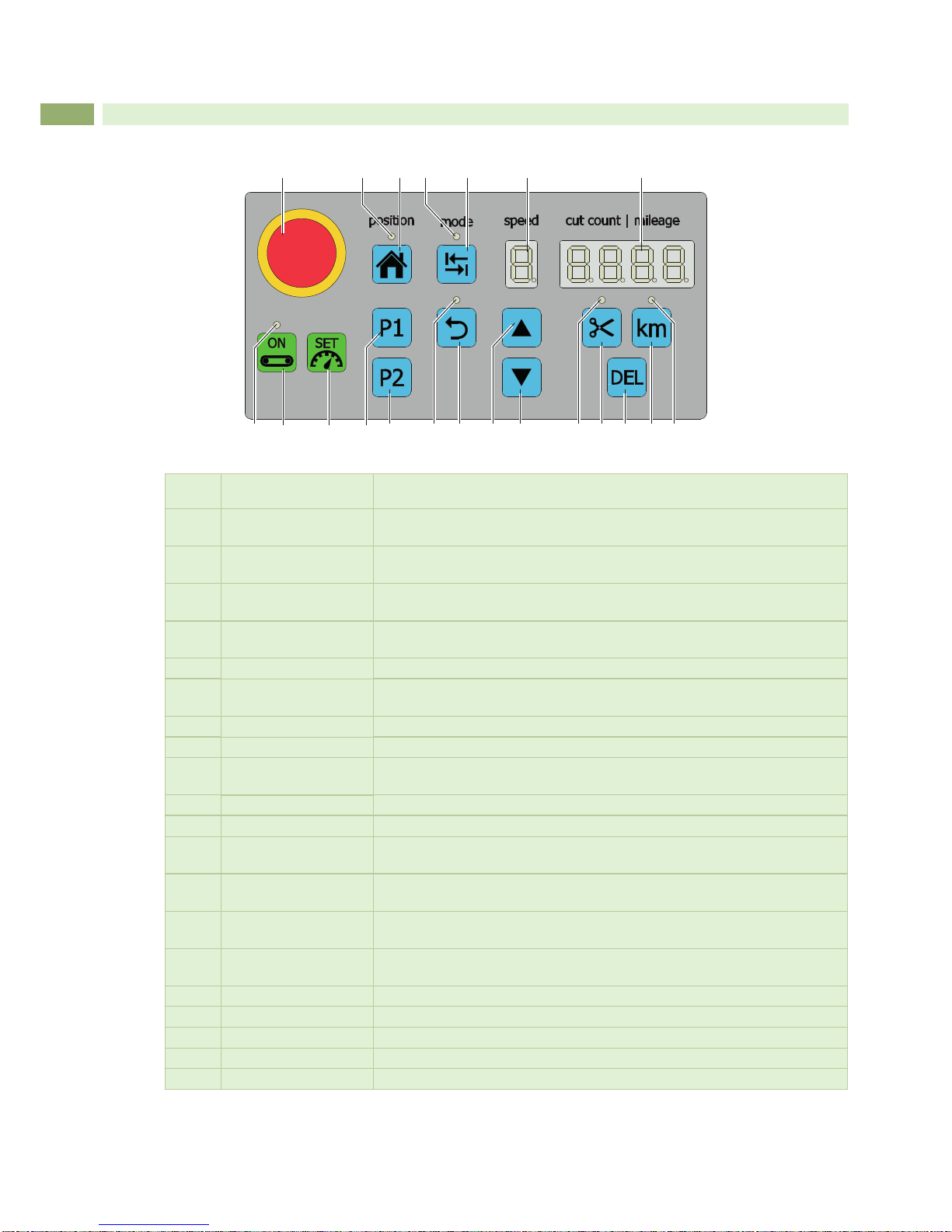
Buttons
- Home / Error acknowledgment during operation
- Adjustment of initial carriage position
- Adjustment of nal carriage position
- Separate carriage movement to and fro
- Continuous carriage movement to and fro
- Separation speed increase
- Separation speed reduction
- “Number of separations”selection
- “Separation length”selection
- Deletion of current selection
With a conveyor belt in use
- Start conveyor belt
- Adjustment of belt speed
Power switch ON/OFF
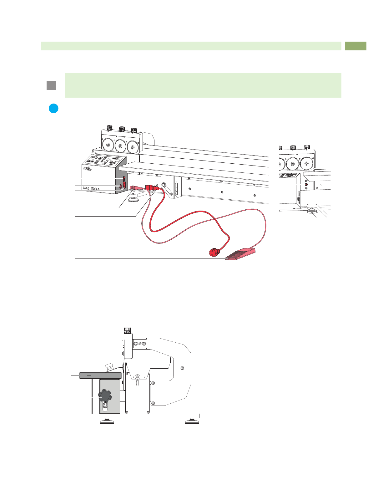
Foot switch START separating
Safety switch E-stop
Power supply 100 - 240 VAC, 50/60 Hz
Emission sound pressure level LpA < 70 dB (A)
Temperature / Operation +5 - 40°C / 10 - 85 % not condensing
humidity Storage 0 - 60°C / 20 - 80 % not condensing
Transpor t –25 - 60°C / 20 - 80 % not condensing
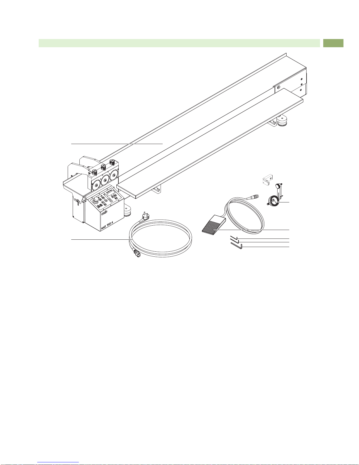
Weight kg 50 55 - -
Height x Depth mm 350 x 450
Width mm 1,150 1,450 1,750 2,050
Approvals CE, FCC
Technical data 6/601 6/601.70 6/901
Type of Component side 1 circular blade
separation Solder side linear blade
Separation path-optimized
Separation speed up to mm/s 500
Material FR4, CEM3
Separation length up to mm 600 900
Support table depth mm 160
Buttons
- Home / Error acknowledgment during operation
- Adjustment of initial carriage position
- Adjustment of nal carriage position
- Separate carriage movement to and fro
- Continuous carriage movement to and fro
- Separation speed increase
- Separation speed reduction
- “Number of separations”selection
- Auswahl der Anzeige „Schnittlänge“
- “Separation length”selection
With a conveyor belt in use
- Start conveyor belt
- Adjustment of belt speed
Power switch ON/OFF
Foot switch START separating
Safety switch E-stop
Power supply 100 - 240 VAC, 50/60 Hz
Emission sound pressure level LpA < 70 dB (A)
Temperature / Operation +5 - 40°C / 10 - 85 % not condensing
humidity Storage 0 - 60°C / 20 - 80 % not condensing
Transpor t –25 - 60°C / 20 - 80 % not condensing
Weight kg 50 55
Height x Depth mm 410 x 450
Width mm 1,150 1,450
Approvals CE, FCC
Table 2 Tecnical Data