www.cablematters.com
1
1. Introduction
1.1 Introduction
Thank you for your purchase from Cable Matters Inc., the ‘Reliable Connectivity’ company.
This User Manual provides an overview of the features and installation of your new
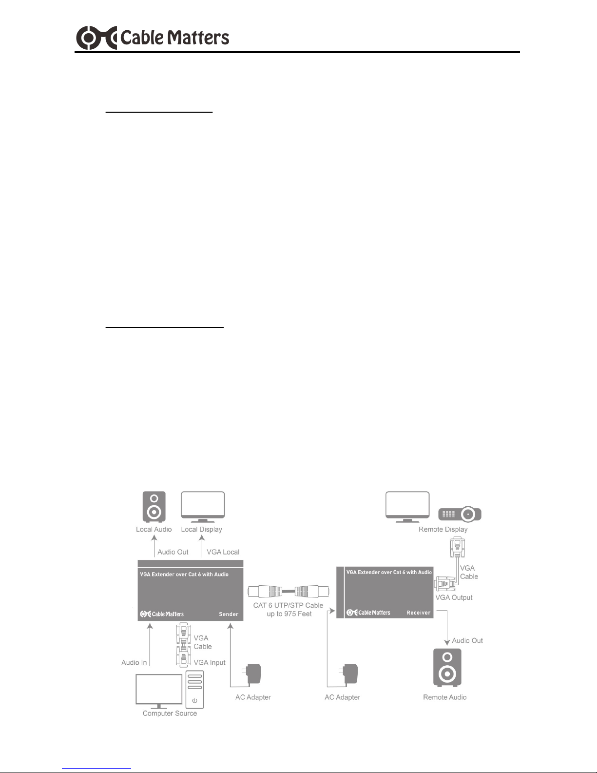
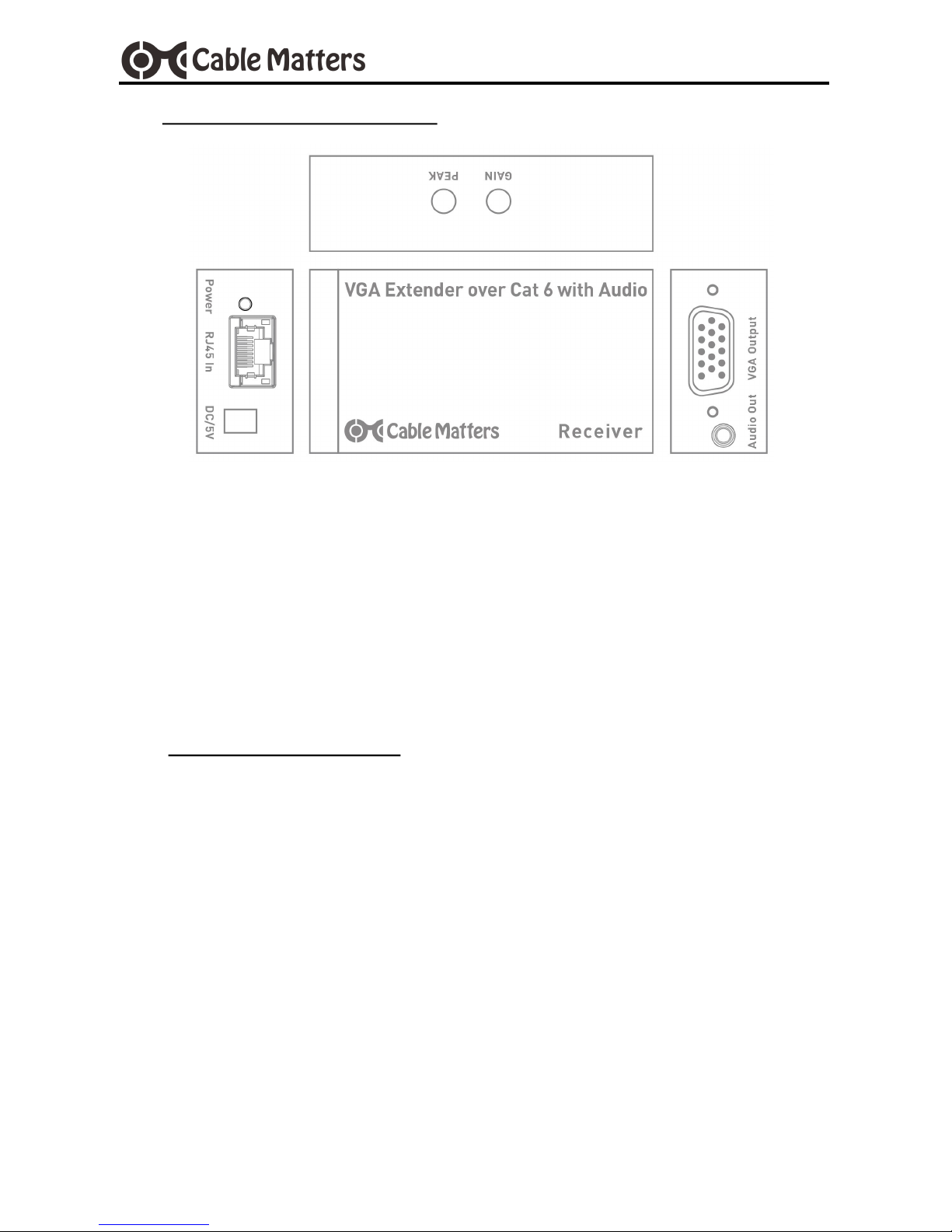
VGA Extender over Cat 6 with Audio Support
Please read these instructions carefully before connecting, operating or configuring
this product. Please keep this user manual for future reference.
Contact support@cablematters.com for questions or product support.
1.2 Copyright and Trademarks
Specifications are subject to change without notice. Cable Matters is a registered trademark or
trademark of Cable Matters Inc. All rights reserved.
This manual may make reference to trademarks, registered trademarks, and other protected
names and/or symbols of third-party companies not related in any way to Cable Matters.
Where they occur these references are for illustrative purposes only and do not represent an
endorsement of a product or service by Cable Matters, or an endorsement of the product to
which this manual applies by the third-party company in question. Regardless of any direct
acknowledgement elsewhere in the body of this document, Cable Matters hereby acknowledg-
es that all trademarks, registered trademarks, service marks, and other protected names and/
or symbols contained in this manual and related documents are the property of their respective
holders.
1.3 FCC Compliance Statement
This equipment has been tested and found to comply with the limits for a Class B digital de-
vice, pursuant to Part 15 of the FCC Rules. These limits are designed to provide reasonable
protection against harmful interference in a residential installation. This equipment generates,
uses and can radiate radio frequency energy and, if not installed and used in accordance with
the instructions, may cause harmful interference to radio communications.
This device complies with part 15 of the FCC Rules. Operation is subject to the following two
conditions: (1) This device may not cause harmful interference, and (2) this device must ac-
cept any interference received, including interference that may cause undesired operation.
FCC Caution: Any changes or modifications not expressly approved by the party responsible
for compliance could void the user's authority to operate the equipment. The device has been
evaluated to meet general RF exposure requirement.