Cadet EPA750 User manual

•Whisper quiet operation and low surface temperatures
•Filled with 80% water 20% Ethylene Glycol
• Self-contained hermetically sealed system requires no
plumbing, piping, or other water supply
•Higher fluid capacity offers better heat retention, which creates
less cycling and keeps more consistent room temperatures
•5-year element warranty
•Carrying handle and 6 foot cord with polarized plug
•Built-in thermostat
1.DO NOT place hands inside the unit or on the heat outlet dur-
ing operation.
2. DO NOT operate the heater unless it is level and the mount-
ing feet and front cover are in place.
3. Do not place heater against paperboard or low-density
fiberboard surfaces.
4. Do not place heater below or above an electrical conve-
nience receptacle.
5. The chemical properties of some synthetic fibers used in
draperies and furniture may cause fading when exposed to
any heat, even at low temperatures. Maintain a 12-inch min-
imum clearance in front and above the heater with a 6-inch
minimum on each side. Draperies in front of heater will
obstruct heat. Cadet cannot be responsible should discol-
oration occur.
6. WARNING
Overheating or fire may occur. DO NOT place the heater
behind doors.
Features & Benefits
OWNER’S GUIDE
The EPA
IMPORTANT INFORMATION
9
1
/
2
"
24,13
Models:
EPA750
EPA1000
EPA1500/3
3
1
/
4
"
8,26
7. WARNING
Overheating or fire may occur. DO NOT operate without legs
attached.
8. WARNING
Fire or explosion may occur. DO NOT place heater in any
area where combustible vapors, gases, liquids, or excessive
lint or dust are present.
9. WARNING
Risk of Electrical Shock. Unplug heater before removing
cover or performing any maintenance.
10. WARNING
Risk of Fire. Heater must be kept clear of all obstructions:
maintain a 12-inch minimum clearance in front and above the
heater with a 6-inch minimum on each side. Heaters must
be kept clean of lint, dirt and debris. (See Maintenance
Instructions)
11. WARNING! Element filled with heat transfer fluid con-
taining 20% Ethylene Glycol and 80% water. In the unlikely
event of leakage, if consumed, call your local poison con-
trol center or seek medical attention immediately.
SAVE THESE INSTRUCTIONS
TEL: 360-693-2505 Fax: 360-694-6939 P.O. Box 1675 Vancouver, WA 98668-1675

PLACEMENT: For best results, place the Softheat baseboard heater under a window, along an outside wall,
or as close as possible to an outside door.
Carefully lift up and pull front cover forward
from the bottom (See Figure 1).
Thoroughly inspect your heater for any shipping
or handling damage and remove any paper or
packaging material found inside the heater. If
there is any indication that fluid has leaked,
return the damaged heater to original purchase
location.
STEP 1 HEATER INSPECTION
STEP 2 REPLACING FRONT COVER
Operation Instructions
The support feet must be securely attached to
the heater as shown in Figure 1 BEFORE operat-
ing the heater. Two plastic support feet and four
mounting screws are provided.
STEP 3 ASSEMBLY
Removing
Front Cover
Screws
Foot
Figure 1.
Place the hooks at each end of the front panel
into the vertical slots located at each end of the
heater. Push the cover back against the heater
at the top until flush, then push downward on
the cover. Cover should lock firmly into place
and MUST be flush with the front before
operating.
HEATER OPERATION
Notice: This heater is a major electrical appliance
and requires adequate electrical connections for
safe use. Plug the heater directly into a wall or floor
receptacle when possible. If an extension cord is
required, use only a heavy duty cord rated for 15
amps minimum . No other major electrical appliance
should be operating on the same circuit.
How To Operate Your Heater
NOTE: Before operating heater,
HEATER INSPEC-
TION
Steps 1 through 3 must be completed:
1) Plug the electrical cord into a 120 volt (AC) out-
let. The plug should fit tightly into the recepta-
cle for a proper electrical connection.
2) Rotate the thermostat control knob clockwise
until the light illuminates, indicating the heating
element is on. Model EPA1500/3 multi-watt units
have a second light (indicating the unit has
power) and a wattage control switch. (See
Figure 2)
3) Allow approximately one hour for the room tem-
perature to completely stabilize. If the room is
still too cool, turn the thermostat knob slightly
clockwise to a higher setting. If the room is too
warm, turn the thermostat knob slightly counter-
clockwise to a lower setting. (Multi-watt mod-
els: if the indicator light remains illuminated and
the room is not warm enough, set the wattage
control knob to the next higher rating.)
4) Once the room has reached a comfortable tem-
perature, turn the thermostat control knob
counter-clockwise until the indicator light goes
out, and the thermostat will maintain room tem-
perature.
This heater is a
major electrical
appliance and
requires adequate
electrical connec-
tions for safe use.
Plug the heater
directly into a wall
or floor receptacle
when possible. If
an extension cord
is required, use
only a heavy duty
cord rated for 15
amps minimum. No
other major elec-
trical appliance
should be operat-
ing on the same
outlet circuit.
WARNING!
Risk of Fire.
Heater must be
kept clear of all
obstructions: 12-
inch minimum
clearance in
front and above
the heater with a
6-inch minimum
on each side.
WARNING!
Risk of Electrical
Shock. Unplug
the unit before
performing any
maintenance on
heater. Failure to
do so could result
in serious injury
or death!
READ ALL INSTRUC-
TIONS AND SAFETY
INFORMATION
Indicator Light
Thermostat
Control Knob
Wattage
Control Switch
Thermostat
Control Knob
Model
EPA750 & EPA1000
Indicator
Lights
Model
EPA1500/3
Figure 2.

How Softheat hydronic baseboards work:
Inside a Softheat baseboard, a hermetically sealed water and
anti-freeze solution is heated by an electric heating ele-
ment. As the solution is heated, warmth is generated and
transmitted through dozens of aluminum fins along the
heater tube (it could initially take 30 to 60 minutes to warm a
room, depending on the room size). As the warmth spreads
outward from the heater, cooler air from the floor and wall nat-
urally flow toward the base of the heater. "Convection air heat-
ing" (See Figure 3) provides heat without fans, preventing the
heater from blowing or burning dust particles. The room is
warmed with even, comfortable heat without cold and hot
spots throughout the room. While Softheat offers everyone
a comfortably warm room, it was specifically designed to
reduce the effects of indoor allergens, compared to other
heating systems. Additional benefits include lower operat-
ing surface temperature and whisper quiet operation.
WARNING!
Element filled with
heat transfer fluid
containing 20%
Ethylene Glycol. In
the unlikely event of
leakage, if consumed,
call your local
poison control cen-
ter or seek medical
attention
immediately.
WARNING!
Risk of Fire. Heaters
must be kept clean
of lint, dirt and
debris.
Failure to follow
warnings may cause
heater to eject
sparks, ignite
materials, or cause
electrical shock.
Cold AirCold Air
Warm Air
Warm Air
Warm Air
Room Air
HEAT
LIMIT CONTROL
HEATING ELEMENTS
RED
RED
BLACK
RED
POLARIZED
BLADE PLUG
CLOSE L1
THERMOSTAT
WATTAGE SWITCH
RED
ON HEAT
LIMIT CONTROL
BLACK
WHITE
POLARIZED
BLADE PLUG
CLOSE L2
THERMOSTAT
OFF L1
WATTAGE SWITCH
HEATING ELEMENTS
Single Pole Thermostat
EPA750 and EPA1000 (120 Volt)
EPA1500/3 (120 Volt)
Model EPA750 EPA1000 EPA1500/3
BTUs 2560 3413 1707/3413/5120
Watts 750 1000 500/1000/1500
Volts (AC) 120 120 120
Phase 111
Hertz 60 60 60
Amps 6.3 8.3 4.2/8.3/12.5
Length* 47” 59” 71”
* Approximate Metric equivalents: 4' = 1,2m, 5' = 1,5m, 6' = 2m.
Operation Instructions
Figure 3.
HEATER MAINTENANCE
SOFTHEAT has no moving parts to wear
out, so it is virtually maintenance-free.
However, it is recommended to periodi-
cally remove the front cover (UNPLUG
UNIT FIRST) and vacuum the lint or
dust from the inside of the heater to
maintain peak heat transfer into the air.
Use caution when vacuuming to avoid
damaging the aluminum fins.
PILOT LIGHT
THERMOSTAT
LIMIT
HEATER TUBE
RED
RED
RED
BLACK
BLACK
RED
HEATER ELEMENT
POLARIZED
BLADE
PLUG
Double Pole Thermostat
EPA750 and EPA1000 (120 Volt)
Please note: If your heater has a thermostat control knob that is labeled with an “OFF” position, the unit
is equipped with a double pole thermostat. No heating will occur when the thermostat is rotated to the
full counterclockwise “OFF” position.

Warranty
CONSULT LOCAL ELECTRICAL CODES TO DETERMINE WHAT WORK MUST BE PERFORMED BY QUALIFIED ELECTRICAL SERVICE PERSONNEL
Gurgling noise
Heater not working
Liquid found in or around
unit
Room does not heat quickly
Heater will not shut off
Unit may not be level
1. Heater does not have power
2. Defective component
Heat transfer fluid may be escaping
from element
Unit is slower to heat
1. Heat loss from room is greater than
heater capacity
2. Defective thermostat
1. Check to be sure unit is level. If gurgling doesn't stop within 30 minutes, unit
needs to be serviced. Do not operate.
1. Check cord to be sure it is securely plugged into receptacle.
2. Unit must be serviced.
1. Immediately discontinue use.
2. Unit must be serviced.
Typical initial warm-up takes 30-60 minutes.
1. Close doors and windows. Provide additional insulation, install a higher-wattage
heater or multiple heaters if necessary.
2. Adjust thermostat to its lowest setting. If heater continues to run (allow two minutes
for the thermostat to respond), replace thermostat.
Symptom Problem Solution
Troubleshooting Chart
Warranty Information
Maintenance: For safer operation and to prolong the life of the heater, it is necessary to follow the maintenance instructions included with each
heater. Failure to properly maintain the heater will result in the warranty being voided. All warranties offered to original consumer only. Warranty
instructions are included with each heater.
LIMITED ONE-YEAR WARRANTY: Cadet Manufacturing Co. will repair or replace any Cadet product, including
thermostats, found to be defective or malfunctioning from first date of purchase through the first year.
LIMITED FIVE-YEAR WARRANTY: Cadet Manufacturing Co. will repair or replace any Cadet/Softheat®baseboard (E) element found to be defective or
malfunctioning from first date of purchase through the fifth year.
THESE WARRANTIES DO NOT APPLY:
1. To conditions resulting from improper installation or incorrect supply voltage;
2. To conditions resulting from improper maintenance, misuse, abuse, accident, or alteration;
3. To service calls or labor involved in replacing defective part(s);
4. If the date of manufacture cannot be determined;
5. To freight damaged products.
CADET SHALL NOT BE LIABLE FOR DAMAGES SUCH AS PROPERTY DAMAGE AND/OR INCIDENTAL EXPENSES RESULTING FROM BREACH OF THESE
WRITTEN WARRANTIES OR ANY IMPLIED WARRANTY.
These warranties give you specific legal rights, and you may also have other rights which vary from state to state.
Cadet neither assumes, nor authorizes anyone to assume for it, any other obligation or liability in connection with these electric heaters or any part
of such heaters.
If the product should become defective during the warranty period, contact Cadet Manufacturing Co. at 360.693.2505 for instructions on how to have
the repair or replacement processed. Products returned without authorization will be refused.
Contact Cadet for information on Parts or Service

•Funcionamiento silencioso y temperaturas de superficie bajas
•Rellenado con 80% de agua, 20% de glicol etilénico
•Sistema autónomo herméticamente sellado que no requiere plomería,
tubería u otro suministro de agua.
•Capacidad superior de líquido que ofrece mejor retención del calor, lo que
crea menos funcionamiento cíclico y mantiene más constantes las
temperaturas del ambiente.
•Garantía de 5 años del elemento
•Manija para transportar y cable de 6 pies con enchufe polarizado
•Termostato incorporado
1. No coloque las manos dentro de la unidad o en la salida de calor
durante su funcionamiento.
2. No ponga el calentador en funcionamiento a menos que esté
nivelado y que las patas de montaje y tapa de adelante estén
colocadas en su lugar.
3. No coloque el calentador contra cartón o superficies de fibra
de baja densidad.
4. No coloque el calentador por debajo o encima de un toma de
corriente conveniente.
5. Las propiedades químicas de algunas fibras sintéticas uti-
lizadas en los cortinados y en muebles pueden decolorarse
cuando se las expone a cualquier tipo de calor, aún a bajas tem-
peraturas. Mantenga un espacio mínimo de 12 pulgadas
enfrente y por encima del calentador con un mínimo de 6 pul-
gadas de cada costado. Los cortinados enfrente del calentador
obstruirán el calor. Cadet no puede responsabilizarse si llegara
a producirse decoloración.
6. ADVERTENCIA
Puede ocurrir un recalentamiento o incendio. NO colocar el
calentador detrás de la puerta.
Características y Beneficios
GUÍA PARA EL PROPIETARIO
EL EPA
INFORMACIÓN IMPORTANTE
9
1
/
2
"
24,13
Modelos:
EPA750
EPA1000
EPA1500/3
3
1
/
4
"
8,26
7. ADVERTENCIA
Puede ocurrir un recalentamiento o incendio. NO poner en
funcionamiento sin que se hayan colocado las patas.
8. ADVERTENCIA
Pueden ocurrir explosiones o incendios. NO colocar el calen-
tador en ningún área donde exista la presencia de vapores,
gases, líquidos combustibles o exceso de pelusa o polvillo.
9. ADVERTENCIA
Riesgo de electrocución. Desenchufar antes de quitar a tapa
o de llevar a cabo cualquier tipo de labor de mantenimiento.
10. ADVERTENCIA
Riesgo de Incendio. El calentador debe mantenerse libre de toda
obstrucción, mantener un espacio mínimo de 12 pulgadas
desde la parte de adelante y por encima del calentador y un mín-
imo de 6 pulgadas de cada costado. Los calentadores deben
mantenerse libres de pelusa, suciedad y residuos (Ver las
Instrucciones para el Mantenimiento).
11. ADVERTENCIA Elemento rellenado con líquido de trans-
ferencia de calor que contiene un 20% de glicol etilénico y
80% de agua. En el improbable caso de que existieran fugas,
de ingerirse, deberá llamar al centro de control de envene-
namientos o solicitar atención médica de inmediato.
CONSERVE ESTAS INSTRUCCIONES
TEL: 360-693-2505 Fax: 360-694-6939 P.O. Box 1675 Vancouver, WA 98668-1675

UBICACIÓN: Para obtener mejores resultados, instalar el calentador de plinto radiante Softheat debajo de
una ventana junto a una pared exterior o tan cerca como resulte posible de una puerta que da al exterior.
Levantar y jalar con mucho cuidado la tapa de
adelante desde la parte inferior. (Ver la Figura1).
Inspeccionar cuidadosamente su calentador
para verificar que el mismo no ha sido dañado
durante el envío o manejo y quitar todo el mate-
rial de embalaje o papeles que se encuentren
en el interior del calentador. Si hubiera alguna
indicación de que ha habido una fuga de líqui-
do, regresar el calentador dañado al lugar de
compra original.
PA S O 1 INSPECCION de la CALENTADORA
PA S O 2 COMO VOLVER A COLOCAR LA
TAPA DE ADELANTE
INSTRUCCIONES PARA EL FUNCIONAMIENTO
Las patas de apoyo deberán adjuntarse de
forma segura en el calentador según se indica
en la Figura 1 ANTES de poner en funcionamien-
to el calentador. Se proporcionan dos patas de
apoyo de plástico y cuatro tornillos de montaje.
PA S O 3 COMO ARMAR
Removing
Front Cover
Screws
Foot
Figura 1.
Coloque los ganchos en cada extremo del panel
de adelante en las ranuras verticales ubicadas
en cada extremo del calentador. Empujar la
tapa hacia atrás contra el calentador en la
parte superior hasta que quede al ras, luego
empuje la tapa hacia abajo. La tapa deberá
calzar muy bien en su lugar y DEBERÁ estar al
ras con la parte de adelante antes de funcionar.
FUNCIONAMIENTO DEL CALENTADOR
ADVERTENCIA: Este calentador es un artefacto
eléctrico de gran envergadura y requiere conex-
iones eléctricas adecuadas para poder usarlo sin
riesgos. Enchufe el calentador directamente en un
tomacorriente mural o de piso cuando sea posible.
Si fuese necesario un cable de extensión, use sólo
uno de servicio pesado apto para 15 amperios como
mínimo. No debe haber ningún otro artefacto eléc-
trico de gran envergadura funcionando
en el mismo circuito.
Como poner en funcionamiento su Calentador
NOTA: Antes de poner en funcionamiento su calen-
tador, deberá completar los Pasos 1 a 3 de
Inspección del Calentador:
1) Enchufe el cable eléctrico en un toma de corri-
ente de 120 voltios (AC). El enchufe deberá calzar
bien en el receptáculo para que haya una conex-
ión eléctrica apropiada.
2) Haga girar la perilla de control del termostato en
el mismo sentido que giran las manecillas del
reloj hasta que la luz se ilumine indicando que el
elemento de calefacción está encendido. Las
unidades de vatiajes múltiples del modelo
EPA1500/ 3 cuentan con una segunda luz (indi-
cando que la unidad está recibiendo energía
eléctrica) y un interruptor para el control del vati-
aje. (Ver la Figura 2).
3) Permita el transcurso de aproximadamente una
hora para que la temperatura del ambiente se
estabilice por completo. Si la habitación sigue
estando demasiado fría, haga girar la perilla del
termostato ligeramente en el mismo sentido que
giran las manecillas del reloj hasta obtener una
graduación más elevada. Si la habitación está
demasiado caliente, haga girar la perilla del ter-
mostato ligeramente en sentido contrario al que
giran las manecillas del reloj hasta obtener una
graduación más baja. (Modelos de múltiples
vatios: si la luz indicadora permanece iluminada
y la habitación no está lo suficientemente
caliente, graduar la perilla de control de vatiaje
hacia la calificación siguiente más alta).
4) Una vez que la habitación haya alcanzado una
temperatura confortable, haga girar la perilla de
control del termostato en sentido contrario al que
giran las manecillas del reloj hasta que la luz del
indicador se apague y el termostato mantendrá
la temperatura ambiente.
Este calentador es
un artefacto eléc-
trico de gran
envergadura y
requiere las conex-
iones eléctricas
adecuadas para
poder usarlo sin
riesgos. Enchufe el
calentador directa-
mente en el toma-
corriente mural o
del piso cuando
sea posible. Si
fuese necesario un
cable de extensión,
use sólo uno de
servicio pesado
apto para 15 ampe-
rios como mínimo.
No debe haber
ningún otro arte-
facto eléctrico de
gran envergadura
funcionando en el
mismo circuito de
salida.
¡ADVERTENCIA!
Riesgo de incen-
dio. El calentador
debe mantenerse
libre de toda
obstrucción: a un
mínimo de 12 pul-
gadas de distancia
en la parte de ade-
lante y arriba del
calentador, con un
mínimo de 6 pul-
gadas de los costa-
dos del mismo.
¡ADVERTENCIA!
Riesgo de elec-
trocución.
Desenchufar la
unidad antes de
llevar a cabo
cualquier servicio
de mantenimiento
en el calentador.
¡No hacerlo podría
resultar en
lesiones graves o
la muerte!
LEER TODAS LAS
INSTRUCCIONES E
INFORMACIÓN
ACERCA DE LA
SEGURIDAD.
Indicator Light
Thermostat
Control Knob
Wattage
Control Switch
Thermostat
Control Knob
Model
EPA750 & EPA1000
Indicator
Lights
Model
EPA1500/3
Figura 2.
Como Quitar
la Tapa de
Adelante
Tornillos
Patas
ADVERTENCIA: Este calentador es un electrodomés-
tico importante que requiere las conexiones eléctric-
as adecuadas para ser utilizado con seguridad.
Enchufar el calentador directamente en un toma de
corriente de la pared o piso cada vez que resulte
posible. Si se requiere una extensión de cable, use
solamente un cable de gran resistencia calificado
para por lo menos 15 amperios. No deberá tener
ningún otro electrodoméstico importante funcionan-
do en el mismo circuito
Luz indicadora
Perilla de control
del termostato
Modelo
EPA750 y EPA 1000
Interruptor de
control del vatiaje
Perilla de control
del termostato
Luces
indicadoras
Modelo
EPA 1500/3

Como funcionan los plintos radiantes hidrónicos Softheat:
En el interior de un zócalo Softheat, hay un sistema de agua y líquido
anticongelante sellado herméticamente, el cual se calienta por un
elemento calefactor eléctrico. A medida que se calienta el sistema, se
genera y transmite calor mediante docenas de aletas de aluminio, a lo
largo del tubo calentador (calentar una habitación podría tardar entre
30 y 60 minutos, según su tamaño). A medida que el calor se dispersa
desde el calentador, el aire frío del piso y de las paredes fluye de man-
era natural hacia la base del calentador. "El calentamiento de aire por
convección" (Consulte la figura 3) brinda calor sin ventiladores, evitan-
do que el calentador sople o queme partículas de polvo. La habitación
se entibia con un calor parejo y agradable sin que queden puntos fríos
ni calientes en ella. Si bien el sistema Softheat deja las habitaciones
agradablemente tibias, fue diseñado específicamente para reducir los
efectos de los alérgenos, en comparación con los demás sistemas de
calefacción. Entre los beneficios adicionales se incluyen una menor
temperatura de operación en la superficie y un funcionamiento con
menos ruido.
¡ADVERTENCIA!
Elemento rellenado
con líquido de
transferencia de
calor que contiene
20% de glicol
etilénico. En el
improbable caso
de que existiera
una fuga, si se
ingiriera, llame al
centro de control
de envenenamien-
tos local o solicite
atención médica
de inmediato.
¡ADVERTENCIA!
Riesgo de incen-
dio. Los calenta-
dores deben
mantenerse libres
de pelusa, polvillo
y residuos.
No respetar las
advertencias
podría hacer que el
calentador despi-
diera chispas,
encendiera materi-
ales o causara la
electrocución.
Cold AirCold Air
Warm Air
Warm Air
Warm Air
Room Air
HEAT
LIMIT CONTROL
HEATING ELEMENTS
RED
RED
BLACK
RED
POLARIZED
BLADE PLUG
CLOSE L1
THERMOSTAT
WATTAGE SWITCH
RED
ON HEAT
LIMIT CONTROL
BLACK
WHITE
POLARIZED
BLADE PLUG
CLOSE L2
THERMOSTAT
OFF L1
WATTAGE SWITCH
HEATING ELEMENTS
EPA 750 y EPA 1000 (120 voltios)
EPA 1500/3 (120 voltios)
Model EPA750 EPA1000 EPA1500/3
BTU 2560 3413 1707/3413/5120
Vatios 750 1000 500/1000/1500
Voltios (AC) 120 120 120
Fase 111
Hertz 60 60 60
Amperios 6.3 8.3 4.2/8.3/12.5
Longitud* 47” 59” 71”
* Medidas métricas aproximadas equivalentes: 4' = 1,2m, 5' = 1,5m, 6' = 2m.
INSTRUCCIONES PARA EL FUNCIONAMIENTO
Figura 3.
MANTENIMIENTO DEL CALENTADOR
Softheat no cuenta con piezas móviles que pueden
gastarse, por lo tanto no necesita virtualmente
ningún mantenimiento. Sin embargo, se recomienda
quitar la tapa de adelante periódicamente (DES-
ENCHUFAR LA UNIDAD ANTES DE HACERLO) y aspi-
rar con una aspiradora la pelusa o polvillo del
interior del calentador para mantener la mayor can-
tidad de transferencia de calor hacia el aire. Tenga
cuidado al aspirar para evitar dañar las aletas de
aluminio.
Encendido Calor
Interruptor de calor
Control del límite
Elementos de calefacción
Apagado Negro
Blanco
Cerrado
Enchufe
polarizado
Rojo
Rojo
Interruptor de vatiaje
Control del límite
Calor
Rojo
Rojo
Termostato
Cerrado
Negro
Enchufe
polarizado
Elementos de calefacción
Aire Frío
Aire Caliente
Aire de la habitación
Observe que: Si el calentador tiene una perilla de control para el termostato rotulada con la posición "OFF"
(Apagado), la unidad cuenta con un termostato de dos polos. No habrá calefacción cuando se gire el ter-
mostato totalmente en sentido contrario a las manecillas del reloj, a la posición "OFF" (Apagado).
PILOT LIGHT
THERMOSTAT
LIMIT
HEATER TUBE
RED
RED
RED
BLACK
BLACK
RED
HEATER ELEMENT
POLARIZED
BLADE
PLUG
Double Pole Thermostat
EPA750 and EPA1000 (120 Volt)
Negro
Negro
Rojo
Rojo
Rojo
Rojo
Elementos de calefacción
límite
Termostato
Enchufe
polarizado

Garantía
CONSULTAR CON LOS CÓDIGOS DE ELECTRICIDAD LOCALES PARA DETERMINAR QUE PARTE DEL TRABAJO DEBE SER REALIZADA POR
PERSONAL DE SERVICIO ELÉCTRICO CALIFICADO.
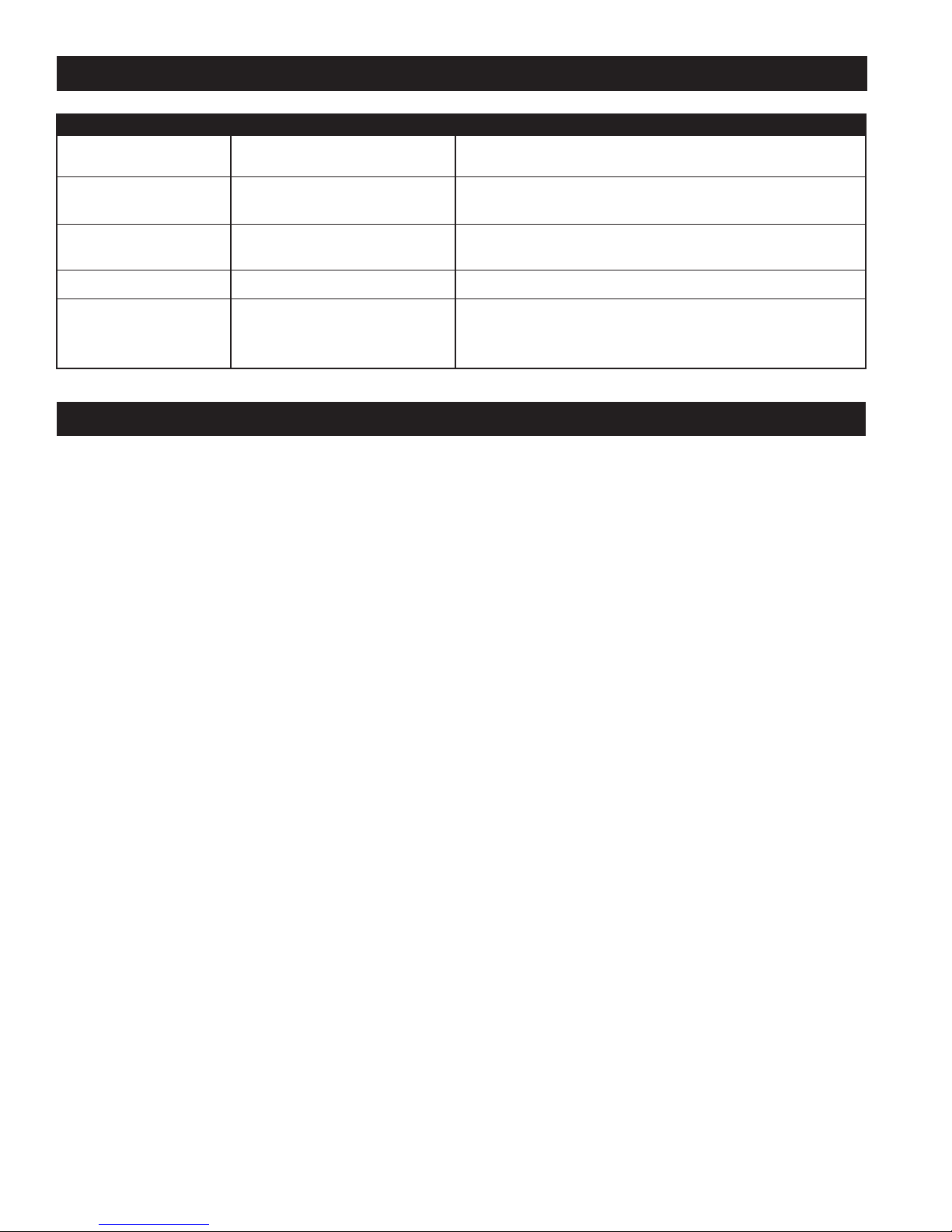
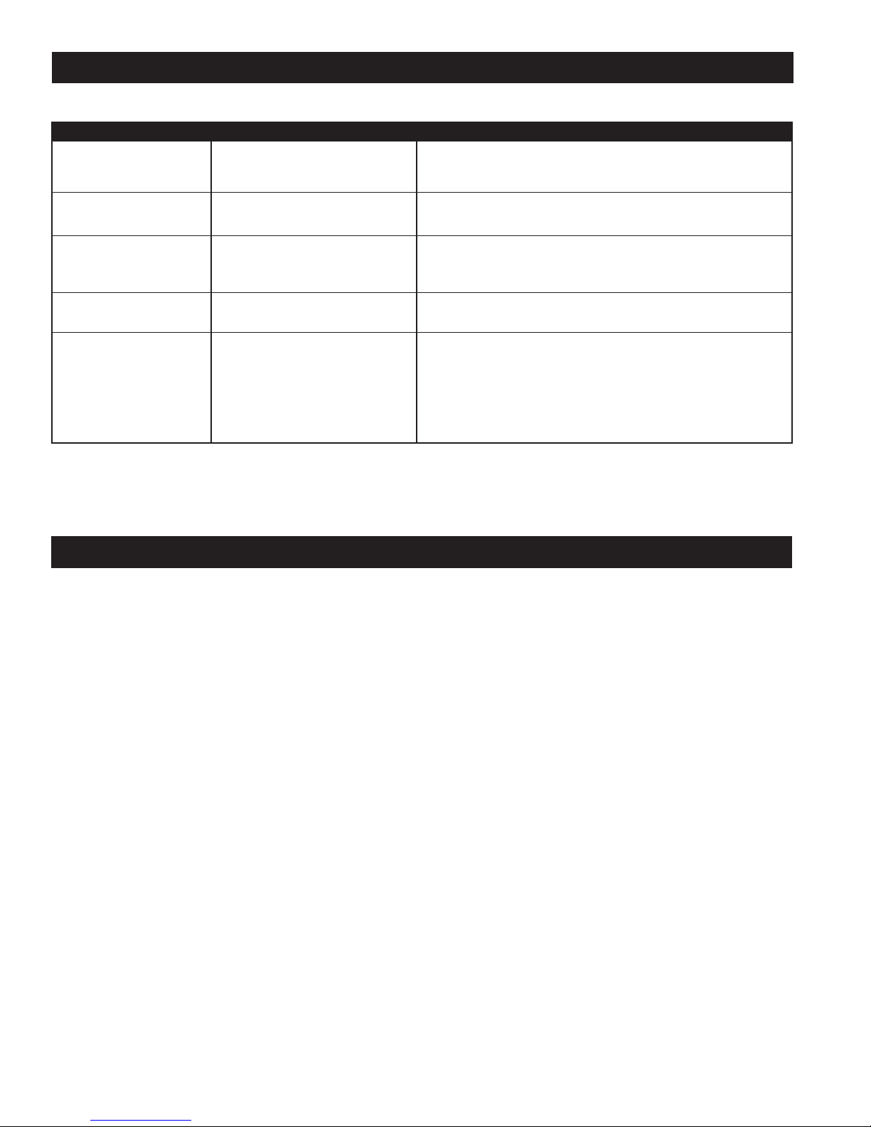
Ruido como gorgoteo
El calentador no funciona
Líquido encontrado en el
interior o alrededor de la
unidad.
La habitación no se calienta
rápidamente
El calentador no se apaga
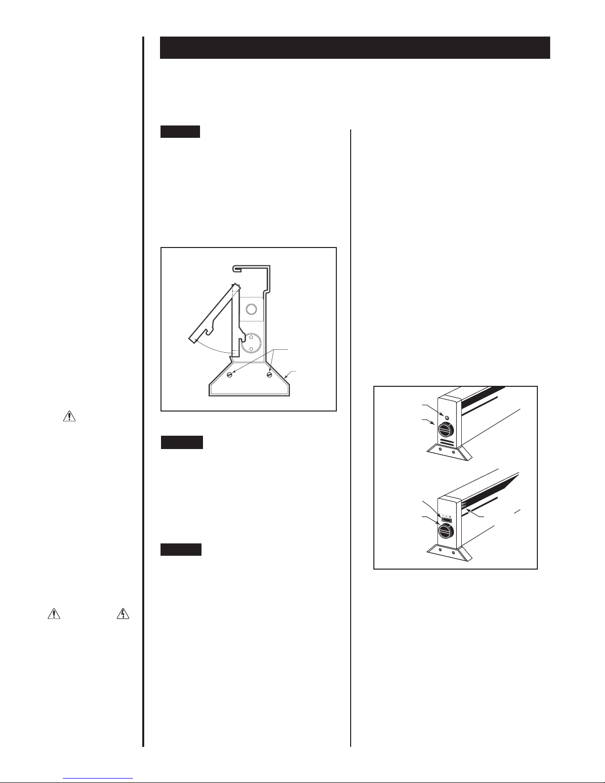
La unidad puede no estar nivelada
El calentador no recibe corriente
eléctrica.
El líquido de transferencia de calor
puede estar escapándose del
elemento.
La unidad tarda más en calentarse.
1. La pérdida de calor en la habitación
es superior a la capacidad del
calentador.
2. Termostato defectuoso.
3. Termostato cableado incorrecta-
mente hacia el calentador.
1. Verificar para asegurarse de que la unidad esté nivelada. Si el sonido no se
detiene dentro de un período de 30 minutos eso significa que la unidad nece-
sita el servicio de reparación. No la ponga en funcionamiento
1. Verifique el cable para asegurarse de que esté bien enchufado en el toma de
corriente.
1. Deje de utilizar inmediatamente
2. La unidad necesita ser reparada.
El entibiamiento inicial típico tarda de 30 a 60 minutos.
1. Cerrar las puertas y ventanas. Proporcionar aislamiento adicional, instalar un calenta-
dor de vatiaje más elevado o múltiples calentadores si fuera necesario.
2. Ajustar el termostato a la graduación más baja. Si el calentador continúa funcionando
(permita el transcurso de dos minutos para que el termostato responda), reemplace el
termostato.
3. Refiérase a la documentación del termostato y cableado correcto.
Síntoma Problema Solución
GUÍA DE RESOLUCIÓN DE PROBLEMAS
Información sobre la Garantía
Mantenimiento: Para un funcionamiento más seguro y para prolongar la vida del calentador, resulta necesario respetar las siguientes instrucciones
de mantenimiento que se incluyen con cada uno de los calentadores. No realizar el servicio de mantenimiento apropiado al calentador resultará en la
anulación de la garantía. Todas las garantías se otorgan solamente al consumidor original. Las instrucciones acerca de la garantía se encuentran
incluidas junto con cada calentador.
GARANTIA LIMITADA DE UN AÑO Cadet Manufacturing Co. reparará o reemplazará cualquier producto Cadet, incluyendo termostatos que se deter-
mine es defectuoso o está funcionando mal desde la fecha de compra original hasta el primer año.
Garantías extendidas para el Producto
Elementos de Plinto Radiante Serie E Cadet/ Softheat
GARANTIA LIMITADA DE CINCO AÑOS: Cadet Manufacturing Co. reparará o reemplazará cualquier elemento (E) de plinto radiante Cadet/Softheat ®
que se determine es defectuoso o está funcionando mal desde la fecha de compra original hasta el quinto año.
ESTAS GARANTíAS NO SON PERTINENTES:
1) Para condiciones que sean el resultado de la instalación inapropiada o del suministro incorrecto de voltaje;
2) Para condiciones que sean el resultado del mantenimiento inapropiado, mal uso, abuso, accidente o alteración
3) Para las llamadas de servicio o mano de obra que involucren el cambio de pieza(s) defectuosa(s)
4) Si no se puede determinar la fecha de fabricación
5) Para los productos dañados durante el flete.
CADET NO SERÁ RESPONSABLE DE LOS DAÑOS A LA PROPIEDAD Y/O GASTOS INCIDENTALES QUE RESULTEN DEL INCUMPLIMIENTO DE ESTAS
GARANTÍAS ESCRITAS O DE CUALQUIER GARANTIA IMPLICITA.
Estas garantías le otorgan derechos legales específicos y es posible que usted cuente con otros derechos que varían de acuerdo a cada estado.
Cadet no asume ni autoriza a nadie para que asuma de su parte ninguna otra obligación o responsabilidad contra terceros relacionada con estos
calentadores eléctricos o con cualquier parte de dichos calentadores.
Si el producto llegara a ser defectuoso durante el período de garantía, comunicarse con Cadet Manufacturing llamando al 360-693-2505 para obten-
er instrucciones acerca de como procesar la reparación o reemplazo. Los productos que se devuelvan sin autorización serán rechazados.
#720183 REV. D 06/04
This manual suits for next models
3
Table of contents
Languages:
Other Cadet Electric Heater manuals

Cadet
Cadet 10F2500 User manual

Cadet
Cadet Baseboard User manual

Cadet
Cadet The Register Plus RM108 User manual

Cadet
Cadet CGH402 User manual

Cadet
Cadet The Com-Pak Bath Heater CB103T User manual

Cadet
Cadet Softheat EBHN500 User manual

Cadet
Cadet 2F500-1 User manual

Cadet
Cadet The Perfectoe UC072 User manual

Cadet
Cadet The Com-Pak Plus C202 reset Guide

Cadet
Cadet RBF101 User manual