manuals.online logo
Brands
  1. Home
  2. •
  3. Brands
  4. •
  5. CADMEN
  6. •
  7. Lighting Equipment
  8. •
  9. CADMEN CM-AF142SO User manual

CADMEN CM-AF142SO User manual

Popular Lighting Equipment manuals by other brands

Life 39.9F70020C quick start guide

Life

Life 39.9F70020C quick start guide

EuroLite LED ML-20 user manual

EuroLite

EuroLite LED ML-20 user manual

LIGMAN OD-50141 installation manual

LIGMAN

LIGMAN OD-50141 installation manual

Home Accents Holiday 1002461144 instructions

Home Accents Holiday

Home Accents Holiday 1002461144 instructions

Experia IRiS Ripple Light instruction manual

Experia

Experia IRiS Ripple Light instruction manual

Erco Gecko Mounting instructions

Erco

Erco Gecko Mounting instructions

Inter-lux ZTA.100.Surface Installation and maintenance instructions

Inter-lux

Inter-lux ZTA.100.Surface Installation and maintenance instructions

Whelen Engineering Company TN Series installation guide

Whelen Engineering Company

Whelen Engineering Company TN Series installation guide

IKEA BJÖRKSPIREA manual

IKEA

IKEA BJÖRKSPIREA manual

Toolland PM 6640 instruction manual

Toolland

Toolland PM 6640 instruction manual

GTD GTD-LP200 user manual

GTD

GTD GTD-LP200 user manual

LIVARNO home 1105-W-UK manual

LIVARNO home

LIVARNO home 1105-W-UK manual

ProLights EclPar IPMFC user manual

ProLights

ProLights EclPar IPMFC user manual

Velvet EVO Series user manual

Velvet

Velvet EVO Series user manual

IDTOLIGHT GENT installation instructions

IDTOLIGHT

IDTOLIGHT GENT installation instructions

MAYTONI S35 installation manual

MAYTONI

MAYTONI S35 installation manual

MaxLite MLFP14DP4535 user manual

MaxLite

MaxLite MLFP14DP4535 user manual

SLV Elektronik 550621 instruction manual

SLV Elektronik

SLV Elektronik 550621 instruction manual

manuals.online logo
manuals.online logoBrands
  • About & Mission
  • Contact us
  • Privacy Policy
  • Terms and Conditions

Copyright 2025 Manuals.Online. All Rights Reserved.

Page 1 of 2
CM-AF142SO
Single Gang Multi-color Dome Light, with Sounder
INSTALLATION INSTRUCTIONS
Door Activation Devices
THIS PACKAGE INCLUDES
1. DESCRIPTION
Camden CM-AF142SO Multi-color Dome Light, provides both
visual and audible annunciation. It mounts to a standard
single gang electrical box. The Superbright LED’s along with
the wedged shaped lamp cover provides visible illumination
from either end of a corridor. The integrated piezo buzzer with
adjustable volume provides up to 93 dB at 1 metre (3 feet).
2. SPECIFICATIONS
Voltage 12/24V AC/DC
Illumination Superbright LED's
Sounder Piezo, 93 dB max. @ 1 metre (3 ft.)
Current Rating 70 mA Max for one color wire.
Combining more than one color
wire = 130 mA.
Dimensions (Body) 4 9/16" H x 2 15/16" W
(115mm x 75mm)
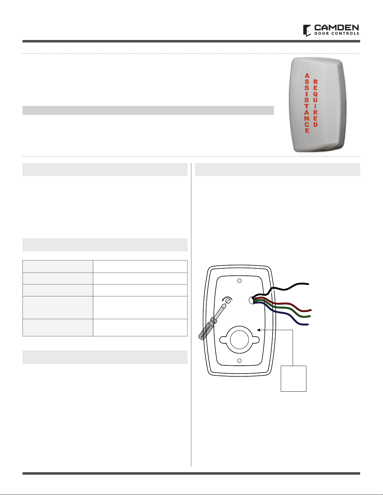
3. SOUND VOLUME ADJUST
Using a small Phillips screwdriver, gently turn the volume
adjustment counter clock wise to reduce the volume and
clockwise to increase the volume.
(1) Foam Gasket
(1) O Ring
(1) Set of Labels
(1) LED Base
(1) Lens
(1) 2-28 x 5/16"
Phillips locking screw
(2) Concrete wall plugs
(2) #6 x 3/4" self-tapping screws
(2) 6-32 x 3/4" screws
(4) Wire nuts
(2) 3/16" drywall plugs
4. WIRING
Camden CM-AF142SO Multi-color Dome Light is easily wired
using the two of the four color coded wires supplied; Black
(BLK), Red (RED), Green (GRN) and Blue (BLU). Using the BLK
wire as common, selecting one of the three color wires to
complete the circuit will determine the color of the Dome light.
The black wire lead and any one of the color coded wires can be
connected to either an AC or DC power source supplying 12
or 24 volts.
12-24
AC/DC
Power
-+
- Use black wire
for common
- Select green wire
for green color
- Select blue wire
for blue color
- Select red wire
for red color
Call: 1.877.226.3369 / 905.366.3377
Visit: www.camdencontrols.com
Opening New Doors to
Innovation, Quality and Support!
Page 2 of 2
CM-AF142SO Single Gang LED Dome Light with Sounder
INSTALLATION INSTRUCTIONS
File: CM-AF142SO-Manual-R2.indd
Revision: 04/07/2019
Part No.: 40-82B228
5. INSTALLATION
CM-AF142SO mounts to a standard single gang electrical box.
Gasket
CM-AF142SO
Base
FLASH RATE:
Increase or decrease
the flash rate by gently
turning the potentiometer
with a small screwdriver.
O Ring
Lens
Locking Screws
A
S
S
I
S
T
A
N
C
E
R
E
Q
U
I
R
E
D
Labels
Labels
Step 1
Place the gasket (supplied)
between the base unit and
the electrical box. Use the
6-32 screws to fasten the
base to the electrical box.
Step 2
Insert the O ring gasket into
the small channel in front of
the base. The O Ring does
not completely close around
the base. You must leave a
small opening at the bottom
of the base.
Step 3
Install the lens
by inserting the
large bottom tab
rst. The top tabs
will snap in place
with little effort.
Step 4
Install the
Phillips locking
screw into the
bottom of
the base.
Step 5
Apply the
labels as
required
to the lens.
4-9/16”
(115mm)
2-15/16” (75mm) 1-9/16”
(40mm)
3-1/16”
(77mm)
3-1/4”
(83mm)
2-1/16” (53mm)