7
www.cagsanmerdiven.com
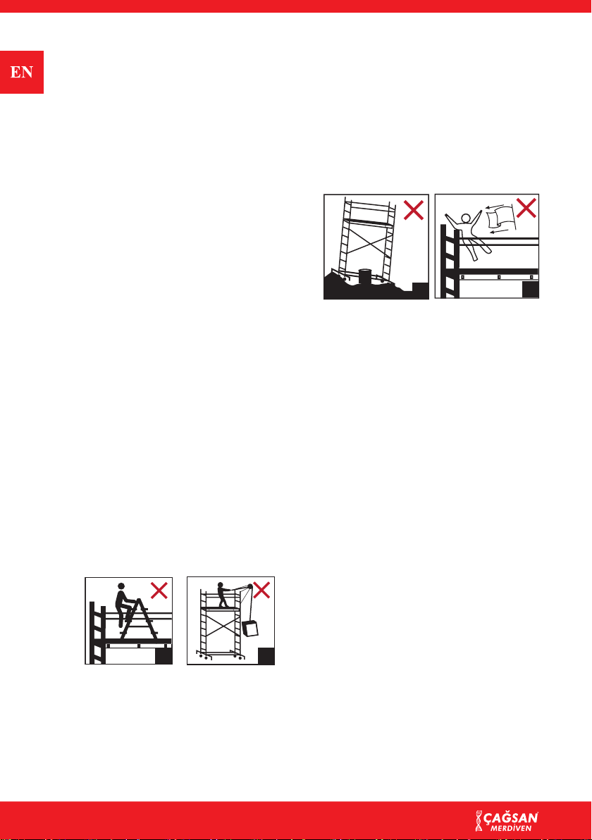
• Environmental factors such as the
previously opened doors, windload,
shades, automatically used sunsha-
des, electricity cables above, trafc
and/or the people crossing the road
etc. should be examined while mo-
ving TeleSafe Scaffold in order to
prevent danger.
• The place of the TeleSafe Scaffold
should only be changed lengthways
or towards cross direction on a surfa-
ce that carries enough at, horizontal
and enough load manually.
• Ensure that TeleSafe Scaffolds does
not tilt while moving.
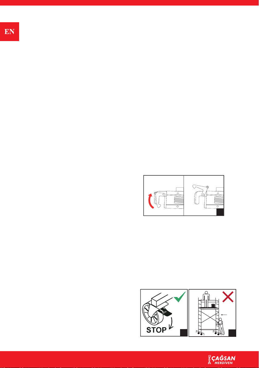
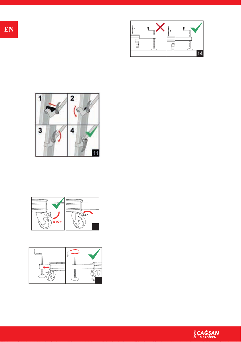
• Right after relocation of TeleSafe
Scaffold, brake pedals should be pus-
hed and wheeled legs should be enga-
ged and locked.
• After relocation, scaffold needs to be
horizontally aligned again, this should
be done by using a level.
• Adjust all stabizers in a way that
they will all contact with the surface.
2.8 Assembly and/or Repair of
Spare Parts
Take into account the national regulations
for inspections, maintanence and repair of
the working towers.
The spare parts provided by Çağsan Mer-
diven should be assembled on the right
product and in the same way as the rep-
laced part.
If assembly (connection) and/or repairs
are performed by the customer, risk and
expenses shall belong to the customer.
Çağsan Merdiven shall not be responsib-
le for damages resulting from wrong as-
sembly and/or repair.
Çağsan Merdiven may provide services
for the repair of your product and/or as-
sembly of the said part with payment
2.9 Guarantee Conditions
Related Çağsan Merdiven product is de-
signed, manufactured carefully and its
necessary quality controls are performed.
If this product is used in compliance with
this instruction and its usage purpose it
shall be under the guarantee with the fol-
lowing conditions:
4. Çağsan Merdiven guarantees the reli-
ability of the product and the quality
of the materials used for the product.
5. If there is a fault in production, the
faulty part or the product is replaced
under the guarantee scope and the
problem is solved.
6. The faults that are not covered with
the guarantee are those stated below:
a) Usage of product in violation of
usage purpose and usage instructions.
b) Normalwearandtear oftheproduct.
c)Assembly or repair performed by
the customer or third parties (the rep-
lacement of spare parts provided by
Çağsan Merdiven as shown in the 2nd
article above is excluded).
7. The faults determined during product
delivery should be immediately in-
formed to Çağsan Merdiven. If these
faults are not immediately informed
the guarantee shall be void. In order
to make a request under the guarantee
scope, Çağsan Merdiven or Çağsan
Merdiven dealer should be informed
about the product delivery and an in-
voice should be submitted.
8. Product faults should be declared to
Çağsan Merdiven or Çağsan Mer-
diven dealer as soon as possible but
within 7 days after the determination
of the fault at the latest.
9. a) If a request is made under the gu-
arantee conditions, Çağsan Merdi-
ven product shall be examined by
Quality Department. Customer ne-
eds to deliver the product to Çağsan
Merdiven for this purpose. If during
the examination it is determined
that the product was inappropriately
used, examination expenses shall
be requested from the customer.
b) If customer requests the exami-
nation to be made by an indepen-
dent organization and if as a result
of the examination it is determined
that the product was used inapprop-
riately, examination expenses shall
be covered by the customer. Even if