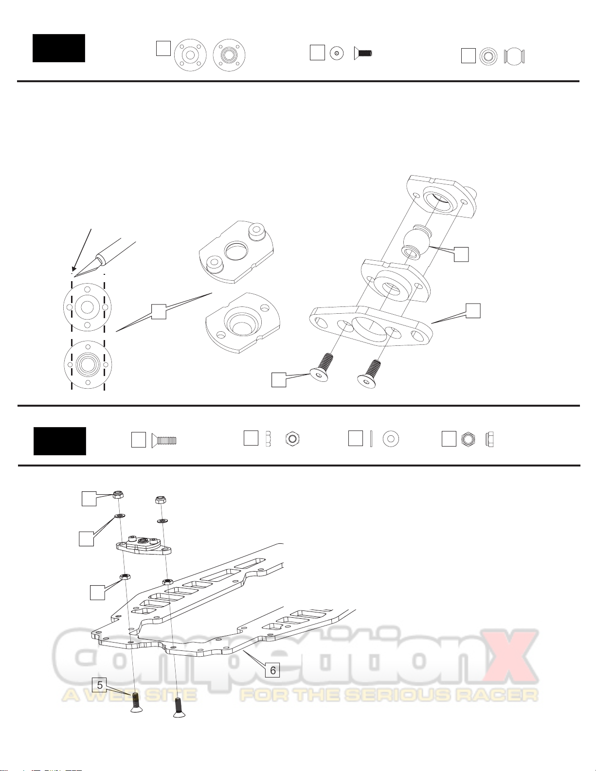
Bag 2
4-40 x 5/16”
FH steel
4-40 x ½”
FH Alum
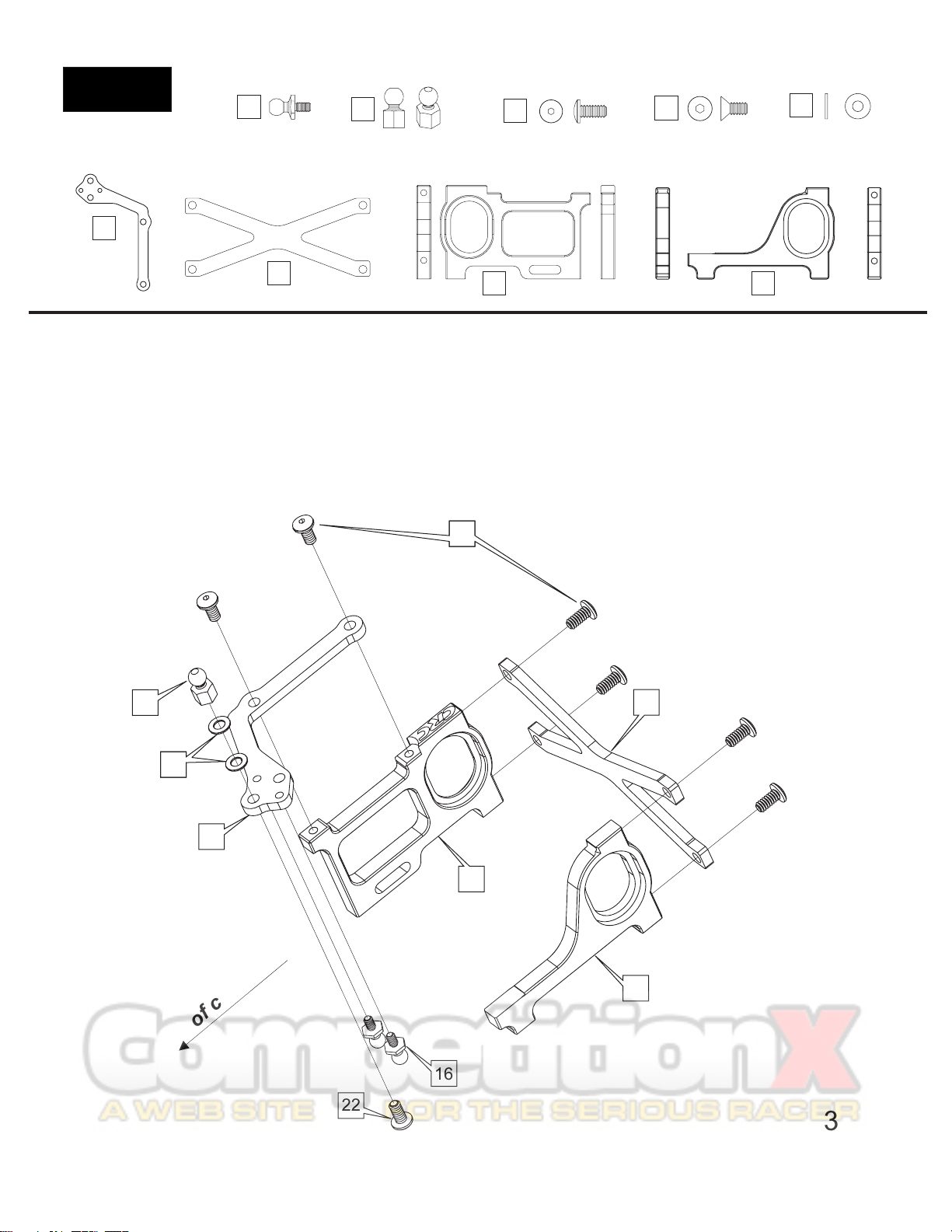
One-Piece
Side Links
Graphite
Bottom Plate
Red Low-
Profile Ball
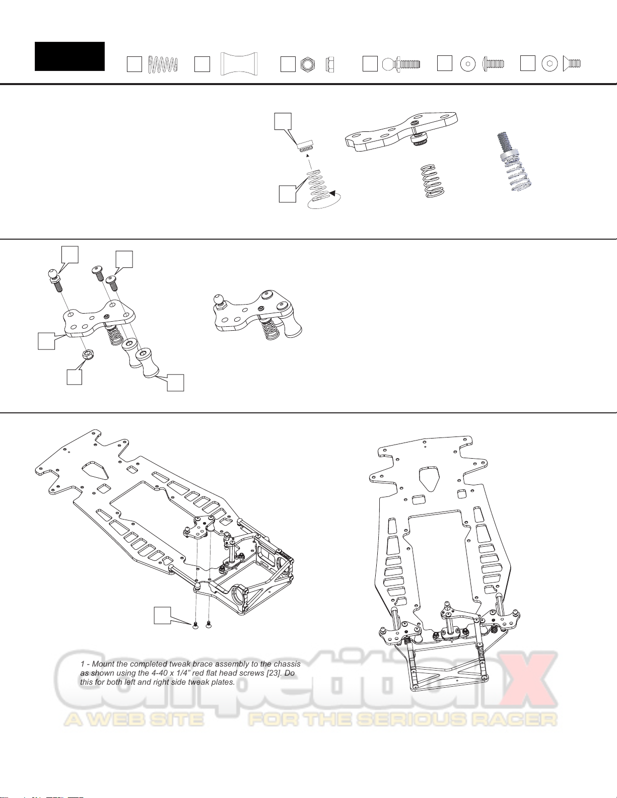
1 - In Bag 2, find the graphite bottom plate
[10]. Secure it to the pivot ball assembly
with the ½” red flat head screw [11]. Secure
it tight with the red 7/8” hex standoff [15].
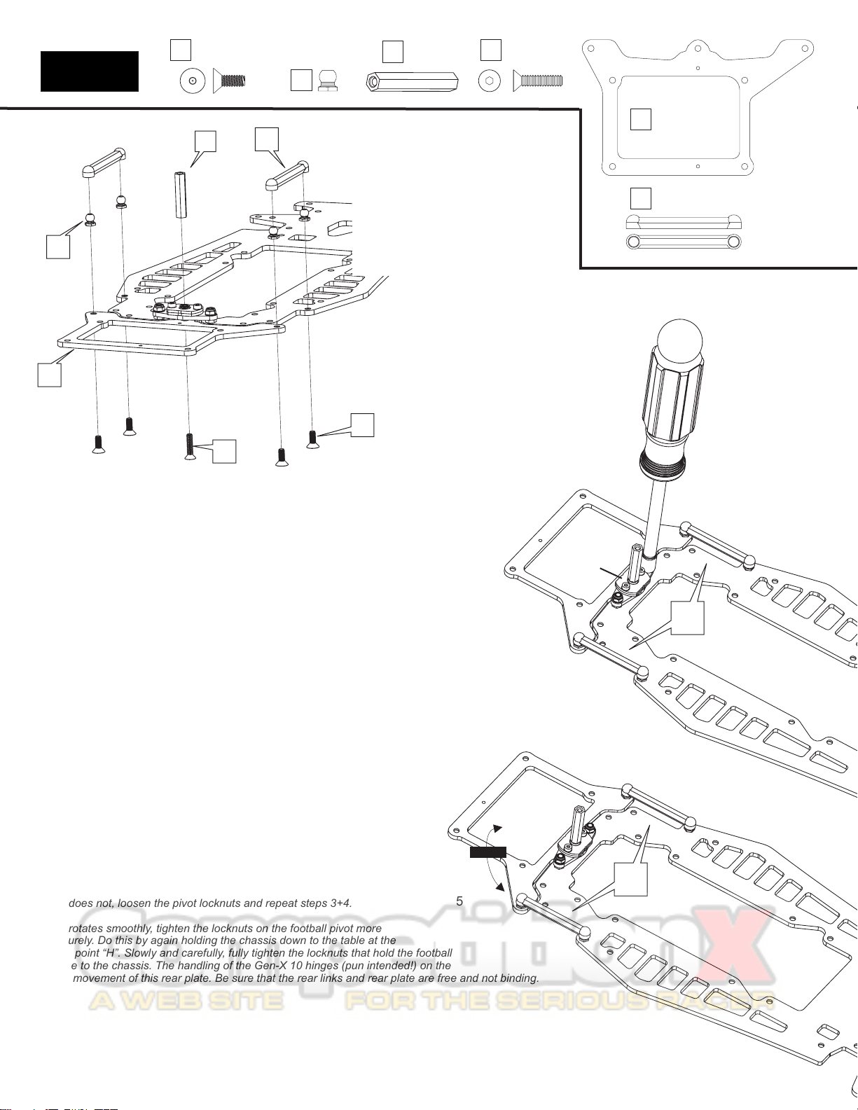
2 - Find the 4 red low profile balls [12].
Secure them as shown with the steel 5/16”
screws [13]. When secure, pop the plastic
side links [14] on the balls.
Be sure the 2 aluminum locknuts on top of the pivot plate are slightly loose.
There should be a washer under each alum locknut. Notice that the pivot plate
“floats" or moves slightly on the 2 screws. This "floating" allows the links
to "free up". This ensures that the rear pod plate pivots freely on the links
and center pivot ball. This is a crucial step when setting up the Gen-X 10.
Snap the 2 links on the balls as shown above. They should rock freely on
the pivot balls.
Place the chassis/backplate on a flat surface. No tires and
no diff on the car! A smooth table or desk should do. Be
sure that the rear bottom plate and chassis are in a
straight line, flat against the table, again, no tires on the
car. Lightly “tap” the chassis and rear pod releasing any
tension in the links. Keep the chassis flat on the table for step 4.
Hold the chassis at the hold point “H” by pressing
the chassis down to the table. Slowly tighten the 2 locknuts that
secure the pivot plate (football shaped part). For now, just lightly
snug one side then the other.
Pick up the car and check the pivoting action of
rear lower plate. Rotate the rear plate from side-to-
side. It should move free without binding or "clicking".
If it does not, loosen the pivot locknuts and repeat steps 3+4.
If it rotates smoothly, tighten the locknuts on the football pivot more
securely. Do this by again holding the chassis down to the table at the
hold point “H”. Slowly and carefully, fully tighten the locknuts that hold the football
piece to the chassis. The handling of the Gen-X 10 hinges (pun intended!) on the
free movement of this rear plate. Be sure that the rear links and rear plate are free and not binding.
(not the rear pod)
1.
2.
3.
4.
5.
5
Rotate
Pivot Plate
Setting the One-piece links
2
Red 7/8”
Standoff
15
10
15
10
11
12
14
13 11
12
13
14
H
H