manuals.online logo
Brands
  1. Home
  2. •
  3. Brands
  4. •
  5. iNels
  6. •
  7. Control Unit
  8. •
  9. iNels RFATV-2 User manual

iNels RFATV-2 User manual

RFATV-2
Wireless thermo-valve
EN
02-4/2022 Rev.0
Made in Czech Republic
1/3
Characteristics /
• The wireless thermo valve measures room temperature and huminity by internal sensor; based
on a set program in the system unit, it opens / closes the radiator valve.
• it can be combinated with these three system units: eLAN-RF 103 or RF Touch 2.
• It measures temperature in a range of 0...+50 °C and sends it to the system unit in regular 2-min.
intervals.
• Monitoring function Open window, where upon a sudden change in temperature, it shuts the
valve for a preset period.
• Setting the hysteresis and offset is performed in the system unit or application.
• Low battery indicator on the display of the system unit or in the application.
• Battery power (1.5 V / 2x AA - included in supply) with battery life of about 1 year based on
frequency of use.
• Range up to 100 m (in open space), if the signal is insufficient between the controller and unit,
use the signal repeater RFRP-20N or protocol component RFIO2that support this feature.
• Communication frequency with bidirectional protocol iNELS RF Control.
• Package includes: 2x battery AA
Description /
Asembly /
RESET button
Temperature and humidity sensor
Battery 2x AA
Central button
LED indication
2. Power:
- open the battery cover.
- insert the batteries (included in packaging, observe the polarity).
- close the battery cover.
1. Asembly:
- if necessary, mount on a suitable adapter to the existing heating valve.
- mount the coupling ring to the valve (adapter).
assembly valve heating /
valve / adapter / wireless thermostat /
ES
ELKO EP, s.r.o. | Palackého 493 | 769 01 Holešov, Všetuly | Czech Republic | e-mail: [email protected] | Support: +420 778 427 366
ELKO EP ESPAÑA, S.L. | C/ Josep Martinez 15a, bj | 07007 Palma de Mallorca | e-mail: [email protected] | Tel.: +34 971 751 425 | Fax: +34 971 428 076
www.elkoep.com / www.elkoep.es
Cabezal termostatico inalámbrico
• El cabezal térmico inalámbrico mide la temperatura y la humedad en la habitación con un
sensor interno y abre/cierra la válvula del radiador según el programa establecido en el
elemento del sistema.
• Se puede combinar con una de las tres unidades del sistema: eLAN-RF 103 o RF Touch 2.
• Mide la temperatura en el rango 0 ... +50 ° C y la envía a la unidad del sistema en intervalos
regulares de 2 minutos. Función "Detección de ventana abierta", cierra la válvula durante
un tiempo predeterminado en caso de un cambio brusco de temperatura. Los ajustes de
histéresis y offset se realizan en la unidad del sistema o en la aplicación.
• Indicación de batería baja en la pantalla de la unidad del sistema o en la aplicación.
• Alimentación de batería 1,5 V / 2x AA - incluidas en el paquete con una vida útil de
aproximadamente 1 año según la frecuencia de uso.
• Alcance hasta 100 m (exterior), en caso de señal insuficiente entre el controlador y el
dispositivo, utilice el repetidor de señal RFRP-20N o componente con el protocolo RFIO2 que
admita esta función.
• Frecuencia de comunicación con protocolo bidireccional RFIO2.
• El termocabezal es compatible con válvulas M30x1.5
• Incluido en el paquete: 2 pilas AA
Característica
Alimentación:
- abra la tapa de la batería.
- inserte las pilas (incluidas, preste atención a la polaridad).
- cerrar la tapa de la batería.
Montaje:
- si es necesario, atornille un adaptador adecuado en la válvula de calefacción existente.
- Enroscar el anillo de conexión en la válvula (adaptador).
montaje en válvula de calefacción
válvula adaptador cabezal térmico inalámbrico
Botón de reinicio
Sensor de temperatura y humedad
Batería 2x AA
Botón central
LED indicación
Descripción del dispositivo
Montaje
RFATV-2
Wireless thermo-valve
EN
02-4/2022 Rev.0
Made in Czech Republic
3.
4.
2/3
Calibration takes approx. 4 s, as soon as the diode starts flashing, the device is ready for pairing.
Use the address to pair with RF Touch, eLAN-RF or RFTC-100 / G (see RF Touch, eLAN-RF or
RFTC-100 / G manual). The RFATV-2 address is located on the bottom of the thermocouple.
Pairing:
1. Press the control button for 10 seconds, which is located on the front of the product
2. The calibration takes place for approx. 4 s, as soon as the diode starts flashing, the device is ready for pairing
3. Pair with eLAN-RF 103 or RF-Touch-2 using the address or QR code. The address is indicated on the body of the device under the battery cover
4. If the head does not pair with any device within 1 minute, it will return to the pre-pairing mode
address /
PROG button
Radio frequence signal penetration through various construction materials /
60 - 90 % 80 - 95 % 20 - 60 % 0 - 10 % 80- 90 %
brick walls wooden structures
with plaster boards
reinforced
concrete metal partitions common glass
xxxxxx
Communication /
RF Touch 2, eLAN-RF-103, eLAN-RF-Wi-103
Interval communication with the control unit in saving mode is 12 minutes.
Interval communication with the control unit in normal mode is 6 minutes.
x
RFRP-20N
ES
ELKO EP, s.r.o. | Palackého 493 | 769 01 Holešov, Všetuly | Czech Republic | e-mail: [email protected] | Support: +420 778 427 366
ELKO EP ESPAÑA, S.L. | C/ Josep Martinez 15a, bj | 07007 Palma de Mallorca | e-mail: [email protected] | Tel.: +34 971 751 425 | Fax: +34 971 428 076
www.elkoep.com / www.elkoep.es
Cabezal termostatico inalámbrico
Transmisión de señales de radiofrecuencia en varios materiales de la construcción
pared de ladrillo estructuras de
madera con placas
de yeso
hormigón armado chapas
metálicas vidrio normal
La calibración tiene lugar durante aproximadamente 4 s, tan pronto como el diodo comienza
a parpadear, el elemento está listo para el emparejamiento.
Utilice la dirección para emparejar con RF Touch, eLAN-RF o RFTC-100/G (consulte el manual
de RF Touch, eLAN-RF o RFTC-100/G). La dirección RFATV-2 se indica en el cuerpo del
elemento debajo de la tapa de la batería.
dirección
Comunicación
PROG botón
RF Touch 2, eLAN-RF-103, eLAN-RF-Wi-103
El intervalo de comunicación con la unidad de control en modo ahorro de energía es de 6 minutos.
El intervalo de comunicación con la unidad de control en modo normal es de 2 minutos.
Emparejamiento:
1. Durante 10 segundos, presione el botón de control, se encuentra en la parte frontal del producto
2. La calibración tiene lugar durante aproximadamente 4 s, tan pronto como el diodo comienza a parpadear, el elemento está listo
para el emparejamiento.
3. Empareje con eLAN-RF 103 o RF-Touch-2 usando la dirección o el código QR. La dirección se indica en el cuerpo del elemento
debajo de la tapa de la batería.
4. Si el cabezal no se empareja con ningún elemento en 1 minuto, volverá al modo de emparejamiento previo
RFATV-2
Wireless thermo-valve
EN
02-4/2022 Rev.0
Made in Czech Republic
3/3
Supply voltage:
Battery life:
Control
Communication protocol:
Frequency:
RF command via controller:
Range:
Other data
Operating temperature:
Working temperature:
Protection:
Dimensions:
Thermovalve nut:
Related standards:
Warning /
Instruction manual is designated for mounting and also for user of the device. It is always a part of its packing.
Installation and connection can be carried out only by a person with adequate professional qualification upon
understanding this instruction manual and functions of the device, and while observing all valid regulations.
Trouble-free function of the device also depends on transportation, storing and handling. In case you notice any
sign of damage, deformation, malfunction or missing part, do not install this device and return it to its seller. It
is necessary to treat this product and its parts as electronic waste after its lifetime is terminated. Before starting
installation, make sure that all wires, connected parts or terminals are de-energized. While mounting and servicing
observe safety regulations, norms, directives and professional, and export regulations for working with electrical
devices. Do not touch parts of the device that are energized – life threat. Due to transmissivity of RF signal, observe
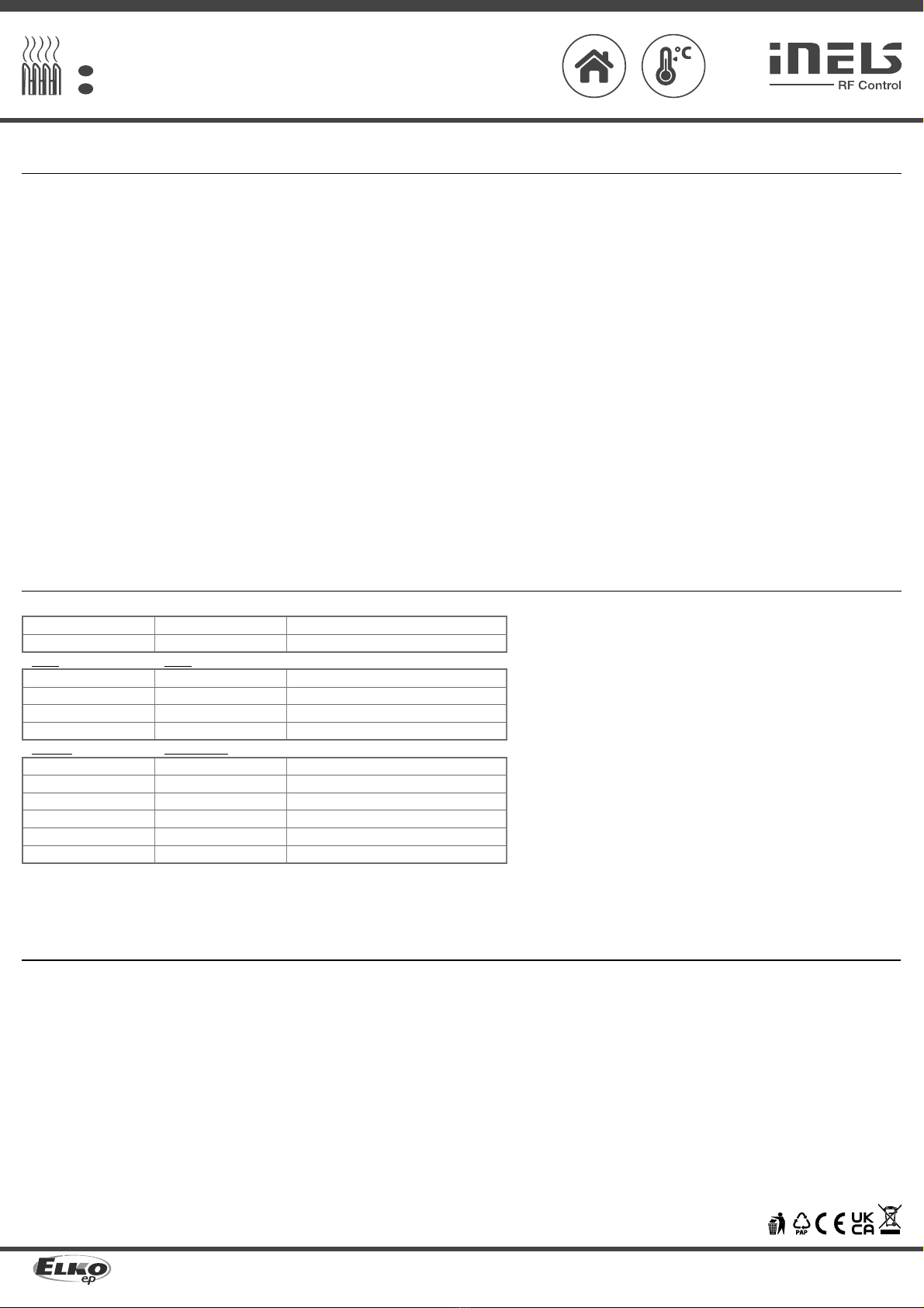
correct location of RF components in a building where the installation is taking place. RF Control is designated only
for mounting in interiors. Devices are not designated for installation into exteriors and humid spaces. The must not
be installed into metal switchboards and into plastic switchboards with metal door – transmissivity of RF signal is
then impossible. RF Control is not recommended for pulleys etc. – radiofrequency signal can be shielded by an
obstruction, interfered, battery of the transceiver can get flat etc. and thus disable remote control.
Technical parameters /
Attention:
When you instal iNELS RF Control system, you have to keep minimal distance 1 cm between
each units.
Between the individual commands must be an interval of at least 1s.
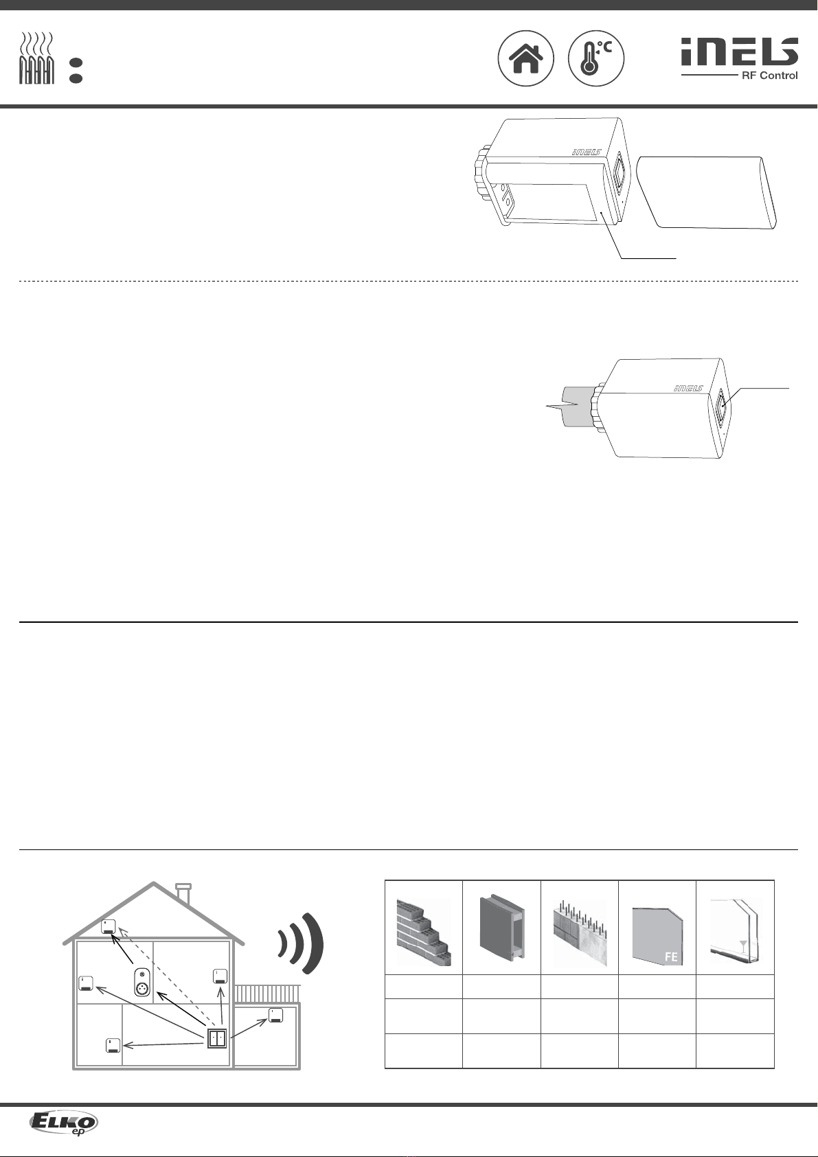
Replacing batteries /
1. open the battery cover
2. remove the batteries
3. insert new batteries (observe the polarity)
4. close the battery cover
5. perform calibration by pressing the central button for 5 s
6. the head returns to operation
Notice:
Only use 1.5V AA batteries correctly inserted in the device!
Do not use rechargeable batteries!
Immediately replace weak batteries with new ones.
Do not use new and used batteries together.
If necessary, clean the battery and contacts prior to using.
Avoid the shorting of batteries! Do not dismantle batteries, do not charge them and protect them
from extreme heating - danger of leakage! Upon contact with acid, immediately rinse the affected
area with a stream of water and seek medical attention.
Keep batteries out of the reach of children.
Batteries must be recycled or returned to an appropriate location (e.g. collection container) in
accordance with local legal provisions.
ES
ELKO EP, s.r.o. | Palackého 493 | 769 01 Holešov, Všetuly | Czech Republic | e-mail: [email protected] | Support: +420 778 427 366
ELKO EP ESPAÑA, S.L. | C/ Josep Martinez 15a, bj | 07007 Palma de Mallorca | e-mail: [email protected] | Tel.: +34 971 751 425 | Fax: +34 971 428 076
www.elkoep.com / www.elkoep.es
Cabezal termostatico inalámbrico
El manual de uso está dirigido para la instalación y el usuario del dispositivo. Manual siempre está incluido en
embalaje. La instalación y conexión puede realizar sólo personal con adecuadas cualificaciones profesionales, de
conformidad con todas las regulaciones aplicadas, y que está perfectamente familiarizado con estas instrucciones
y funciones del dispositivo. Función del dispositivo también depende del transporte, almacenamiento y la manipu-
lación. Si se observa cualquier signo de daño, deformación, mal funcionamiento o pieza que falta, no instale este
producto y devolvelo al vendedor. Con el producto y sus componentes debe ser tratado después de su vida útil
como con residuos electrónicos. Antes de iniciar la instalación, asegúrese de que todos los cables, partes o termi-
nales conectados están sin la conexión a la red. En el montaje y el mantenimiento se deben observar las normas de
seguridad, normas, directivas y reglamentos para trabajar con equipos eléctricos. No toque las partes del dispositivo
que están conectadas en la red - puede producir peligro de vida. Debido a la transmisibilidad de la señal RF, observe
la correcta ubicación de los componentes RF en un edificio donde la instalación se lleva a cabo. RF Control está
diseñado para montaje en interiores, las unidades no están diseñados para la instalación en exteriores y espacios
húmedos, no se pueden instalar en cuadros eléctricos de metal y en cuadros eléctricos plásticos con puerta de
metal - lo que empeora transmisividad de la señal RF. RF Control no se recomienda para el control de dispositivos
que ofrecen funciones vitales o para controlar dispositivos tales como bombas, el. calentadores sin termostato,
ascensores, montacargas, etc. - Señal de radiofrecuencia puede estar bloqueado por una obstrucción, interferida,
la batería del controlador puede estar ya sin energía, etc. y por lo tanto el control remoto puede ser incapacitado.
Especificaciones
Tensión de alimentación:
Duración de la batería:
Control
Protocolo de comunicación:
Frecuencia:
Col la orden RF del controlador:
Rango:
Más información
Temperatura de trabajo:
Posición de funcionamiento:
Protección:
Dimensiones:
Extremo de la termoválvula:
Normas conexas:
Advertencia
Advertencia:
Entre los diferentes ordenes debe pasar al menos 1s.
Reemplazo de baterías
1. abre la tapa de la batería
2. retire las baterías
3. inserte pilas nuevas después de 30 s (preste atención a la polaridad)
4. cierre la tapa de la batería
5. realizar la calibración presionando el botón central durante 5 s
6. termocabezal vuelve a funcionar
Aviso:
¡Utilice únicamente pilas AA de 1,5 V, correctamente insertadas en el dispositivo!
¡No use baterías recargables!
Reemplace las baterías débiles por otras nuevas inmediatamente.
No mezcle pilas nuevas y usadas.
Si es necesario, limpie las baterías y los contactos antes de usarlos.
¡Evite cortocircuitar las baterías! No desmonte ni cargue las baterías, proteja las del calor extre-
mo: ¡riesgo de fugas! En caso de contacto con el ácido, lávese inmediata y abundantemente con
agua y acúdase a un médico.
Mantenga las baterías fuera del alcance de los niños.
Las baterías deben reciclarse o devolverse a un lugar adecuado (e.j. contenedores de reciclaje)
de acuerdo con las reglamentaciones locales.
2 x 1.5 Vbatteries / batería AA
1 year / año
RFIO2
866–922 MHz
eLAN-RF-103, RF Touch-2
up to / hasta 100 m
0 ... +50 °C
any / ningún
IP40
52 x 52 x 70 mm
M 30 x 1.5
EN 60730

Other iNels Control Unit manuals

iNels EST-2 Series Simple manual

iNels

iNels EST-2 Series Simple manual

iNels CU3-01M User manual

iNels

iNels CU3-01M User manual

iNels IM2-80B User manual

iNels

iNels IM2-80B User manual

iNels IM2-80B User manual

iNels

iNels IM2-80B User manual

iNels RFSAI-161B User manual

iNels

iNels RFSAI-161B User manual

iNels EST3 User manual

iNels

iNels EST3 User manual

iNels RF KEY-40/W User manual

iNels

iNels RF KEY-40/W User manual

iNels CU3-01M User manual

iNels

iNels CU3-01M User manual

iNels RFATV-1 User manual

iNels

iNels RFATV-1 User manual

iNels RF KEY-40/W User manual

iNels

iNels RF KEY-40/W User manual

iNels eLAN-RF-Wi-003 User manual

iNels

iNels eLAN-RF-Wi-003 User manual

Popular Control Unit manuals by other brands

ProSoft inRAx MVI56-MNETCR user manual

ProSoft

ProSoft inRAx MVI56-MNETCR user manual

Fluidmaster 402CARHR Quick install guide

Fluidmaster

Fluidmaster 402CARHR Quick install guide

MD mXion MZSpro user manual

MD

MD mXion MZSpro user manual

Murata LBEE5HY2DU user manual

Murata

Murata LBEE5HY2DU user manual

Honeywell 2MLL-PSRA user guide

Honeywell

Honeywell 2MLL-PSRA user guide

ADTRAN Job Aid+ 1442804G1 manual

ADTRAN

ADTRAN Job Aid+ 1442804G1 manual

Kramer RC-52A user manual

Kramer

Kramer RC-52A user manual

ZURN AquaVantage ZH Series Installation, operation, maintenance and parts manual

ZURN

ZURN AquaVantage ZH Series Installation, operation, maintenance and parts manual

Panduit PVQ-PM installation instructions

Panduit

Panduit PVQ-PM installation instructions

RadiSys PROMENTUM ATCA-4300 installation guide

RadiSys

RadiSys PROMENTUM ATCA-4300 installation guide

Elster Instromet 300 Series Operation, Installation & Repair Parts

Elster Instromet

Elster Instromet 300 Series Operation, Installation & Repair Parts

Agilent Technologies G1360A Installation note

Agilent Technologies

Agilent Technologies G1360A Installation note

Hayward H-Power HPOW230BDT50 user guide

Hayward

Hayward H-Power HPOW230BDT50 user guide

ETAS ES432.1 user guide

ETAS

ETAS ES432.1 user guide

HBM MP70DP operating manual

HBM

HBM MP70DP operating manual

LELY E-LINK D 6060 operating manual

LELY

LELY E-LINK D 6060 operating manual

HP R6000 - UPS - Lead Acid Expandable installation instructions

HP

HP R6000 - UPS - Lead Acid Expandable installation instructions

Graco CSP Series instructions

Graco

Graco CSP Series instructions

manuals.online logo
manuals.online logoBrands
  • About & Mission
  • Contact us
  • Privacy Policy
  • Terms and Conditions

Copyright 2025 Manuals.Online. All Rights Reserved.