manuals.online logo
Brands
  1. Home
  2. •
  3. Brands
  4. •
  5. CALEFFI
  6. •
  7. Control Unit
  8. •
  9. CALEFFI 636 series User manual

CALEFFI 636 series User manual

Valvole di regolazione a due e tre vie, attacchi flangiati
Two- and three-way regulating valves, flanged connections
2- und 3-Wege-Regelventile, Flanschanschlüsse
Vannes de régulation deux et trois voies, à brides
Válvulas de regulación de dos y tres vías, conexiones con brida
Válvulas de regulação de duas e três vias, ligações flangeadas
Twee- en driewegventielen, flensaansluitingen
H0006512.01
I
EN
DE
FR
ES
PT
NL
Le valvole di regolazione possono essere utilizzate all’interno di circuiti chiusi degli impianti di
riscaldamento e raffrescamento per il controllo della portata (valvole a due vie) e per il controllo
della temperatura (valvole a tre vie) attraverso la miscelazione del fluido del circuito primario
con quello di ritorno dall’impianto, allo scopo di ottenere la temperatura desiderata di mandata
all’utenza.
Sono caratterizzate da una via di regolazione con caratteristica equipercentuale (valvole a due e
tre vie) ed una via di bypass (valvole a tre vie) con caratteristica lineare. Questa caratteristica di
regolazione garantisce una miglior risposta del sistema alle varie condizioni di carico.
Possono essere abbinate a servomotori proporzionali con segnale di comando 0÷10 V oppure
2 o 3 punti, a seconda delle esigenze del carico termico da controllare.
Regulating valves may be used in the closed circuits of heating and cooling systems, to control
low rate (two-way valves) and to control temperature by mixing the primary circuit medium with
the system return medium (three-way valves) in order to obtain the desired flow temperature
to the utility.
They have one regulation port with an equal percentage characteristic (two- and three-way
valves) and one by-pass port (three-way valves) with a linear characteristic. This adjustment
characteristic guarantees the best possible system response to the various load conditions.
They may be used in conjunction with proportional actuators with a 0-10 V or 2- or 3-point
command signal, depending on the requirements of the thermal load to be controlled.
Die Regelventile können in geschlossenen Kreisläufen von Heiz- und Kühlanlagen verwendet
werden. Sie dienen zur Kontrolle des Volumenstroms (2-Wege-Ventile) und zur Kontrolle der
Temperatur (3-Wege-Ventile) durch Beimischung des Mediums im Primärkreis mit dem des
Anlagenrücklaufs, um die gewünschte Temperatur für den Verbraucher zu erhalten.
Sie verfügen über einen Regelweg in gleichprozentiger Ausführung (Zwei- und Dreiwegeventile)
und einen Bypass-Weg (Dreiwegeventile) in linearer Ausführung. Diese Regelungseigenschaft
garantiert eine bessere Reaktion des Systems auf die verschiedenen Lastbedingungen.
Sie können mit proportional regelnden Stellantrieben mit 0-10 V Steuersignal bzw. 2- oder
3-Punktreglern kombiniert werden, abhängig von den Anforderungen der zu steuernden
Wärmelast.
Les vannes de régulation peuvent être utilisées sur les circuits fermés des installations de
chauffage et de rafraîchissement pour contrôler le débit (vannes deux voies) et pour réguler la
température (vannes trois voies) par le mélange du fluide du circuit primaire avec celui du circuit
de retour, afin d’obtenir la température de départ voulue pour l’installation.
Elles présentent une voie de régulation à caractéristique équipourcentage (vannes deux et trois
voies) et une voie de by-pass (vannes trois voies) à caractéristique linéaire. Ces caractéristiques
de régulation garantissent une meilleure réponse du système aux variations de charge.
Ces vannes peuvent être associées à des servomoteurs proportionnels avec signal de
commande 0-10 V ou à 2 ou 3 points, selon les exigences de la charge thermique à contrôler.
1
www.caleffi.com
Funzione
Function
Funktion
Fonction
Función
Função
Functie
636 series
© Copyright 2020 Caleffi
Las válvulas de regulación se pueden utilizar en los circuitos cerrados de las instalaciones
de calefacción y refrigeración para controlar el caudal (válvulas de dos vías) y la temperatura
(válvulas de tres vías), mezclando en este caso el fluido del circuito primario con el retorno de
la instalación para obtener la temperatura deseada.
Están realizadas con una vía de regulación de característica equiporcentual (válvulas de dos y
tres vías) y una vía de baipás (válvulas de tres vías) con característica lineal. Esta característica
de regulación mejora la respuesta del sistema al variar la carga.
Se pueden combinar con servomotores proporcionales con señal de mando de 0-10V o de
2 o 3 puntos, según las necesidades de control de la carga térmica.
As válvulas de regulação podem ser utilizadas em circuitos fechados de instalações de
aquecimento e de arrefecimento para controlo do caudal (válvulas de duas vias), e para
controlo da temperatura (válvulas de três vias) através da mistura do fluido do circuito primário
com o de retorno da instalação, com o intuito de obter a temperatura de ida desejada no
ponto de utilização.
Possuem uma via de regulação com característica de igual percentagem (válvulas de duas e
três vias) e uma via de bypass (válvula de três vias) com característica linear. Esta característica
de regulação garante uma melhor resposta do sistema às várias condições de carga.
Podem ser acopladas a servomotores proporcionais com sinal de comando 0–10 V ou de 2
ou 3 pontos, consoante as exigências da carga térmica a controlar.
Deze regelventielen kunnen in gesloten circuits van verwarmings- en koelinstallaties
worden gebruikt voor regeling van het debiet (tweewegventielen) en van de temperatuur
(driewegventielen) door menging van de vloeistof van het primaire circuit met die van het
retourcircuit van de installatie, met het doel de gewenste temperatuur te bereiken in de aanvoer
naar het tappunt.
De ventielen worden gekenmerkt door een regelweg met verdeling in gelijke percentages
(twee- en driewegventielen) en een bypassweg (driewegventielen) met lineaire karakteristiek.
Deze regelkarakteristiek garandeert een betere respons van het systeem op verschillende
belastingscondities.
Ze kunnen worden gecombineerd met proportionele servomotoren met besturingssignaal van
0-10 V of 2 of 3 punten, afhankelijk van de vereisten die worden opgelegd door de thermische
belasting die moet worden geregeld.
2
636024 24 V 1000 N 636034 24 V 2500 N
636060 DN65
636080 DN80
636100 DN100
636120 DN125
636150 DN150
636
Two-/three-way version
The valve can be transformed into a two-way valve by
opening the central third port
636
24 V version
2/3 point
0–10 V
636
24 V version
2/3 point
0–10 V
Product range
Valve code Kv
Max. ΔP with 636024
(1000 N)
Max. ΔP with 636034
(2500 N)
636060 63 2,5 bar 1 bar 3 bar 1 bar
636080 100 1,5 bar 0,7 bar 3 bar 0,8 bar
636100 160 - 2 bar
0,5 bar636120 220 - 1,5 bar
636150 320 - 1 bar
3
Materials: - body: grey cast iron EN-GJL-250
- seat, control passage: grey cast iron EN-GJL-250
- seat, mixing passage: stainless steel EN 10088-3 (AlSl 420)
- spindle: stainless steel EN 10088-3 (AlSl 420)
- plug: stainless steel EN 10088-3 (AlSl 420)
Medium: water, glycol solutions
Max. percentage of glycol: 50 %
Max. working pressure: 16 bar
Working temperature range: 0–100 °C
Leakage rate, control passage: ≤0,1 % Kvs
Nominal stroke: 20 mm (DN 65...80)
40 mm (DN 100...150)
Valve characteristic, control passage: equal percentage
Valve characteristic, mixing passage: linear
Connections: DN65, 80, 100, 125, 150; PN16 - EN1092-1
Valve technical
specification
Actuator technical specification
Hydraulic characteristics
636024
(AVM3225F132)
636034
(AVM2345F132)
Type Synchron motor
Electrical supply 24 V (AC)/(DC)
Power consumption 3,5 VA 20 VA
Control signal 2/3 point, 0–10 V
Nominal force 1000 N 2500 N
Protection class IP 54 IP 66
Operating time 80/120 s 40/80/120 s DN65-DN80
80/160/240 s DN100–DN150
Ambient temp. range -10–55 °C -10–55 °C
4
Installazione
Installation
Installation
Installation
Instalación del aparato
Instalação
Installatie
Configurazione 2 vie.
2-way configuration.
2 Wege-Konfiguration.
Configuration 2 voies.
Configuración 2 vías.
Configuração 2 vias.
2-wegconfiguratie.
Configurazione 3 vie (miscelatrice).
3-way configuration (mixer).
3 Wege-Konfiguration (Mischventil).
Configuration 3 voies (vanne
mélangeuse).
Configuración 3 vías (mezcladora).
Configuração 3 vias (misturadora).
3-weg configuratie (mengventiel).
2
A
AB
B
AB
A
1
AB
A
A
B
AB
5
Configurazione 3 vie (deviatrice).
3-way configuration (diverting).
3 Wege-Konfiguration (Umschalten).
Configuration 3 voies (déviation).
Configuración 3 vías (desviadora).
Configuração 3 vias (desviadora).
3-weg configuratie (verdeelstand).
3
4
AB
B
A
Rimuovere la flangia inferiore per configurazioni a 3 vie.
Remove the lower flange for 3-way configurations.
Den unteren Flansch für die 3-Wege-Konfiguration entfernen.
Retirez la bride inférieure pour les configurations à 3 voies.
Quite la brida inferior para configuración de 3 vías.
Remover a flange inferior para configurações de 3 vias.
Verwijder de onderste flens voor 3-weg configuraties.
6
Montaggio consigliato per evitare forti rumori
dovuti al flusso d’acqua negli impianti di
riscaldamento e raffrescamento.
Recommended installation to prevent noisy
water flow in the heating and cooling systems.
Empfohlene Montage zur Vermeidung von
starken Fließgeräuschen des Wassers in Heiz-
und Kühlanlagen.
Montage conseillé pour éviter que le flux d’eau
devienne très bruyant dans les installations de
chauffage et de rafraîchissement.
Montaje aconsejado para minimizar los
ruidos causados por el flujo de agua en las
instalaciones de calefacción y refrigeración.
Montagem recomendada para evitar ruídos
fortes do fluxo causados pela água nas
instalações de aquecimento e arrefecimento.
Aanbevolen montage ter voorkoming van
harde geluiden door stromend water in
verwarmings- en koelinstallaties.
M = 50%: 1,2,3,4
M = 100%: 5,6,7,8 M = 50%: 1,2,3,4,5,6,7,8
M = 100%: 9,10,11,12,13,14,15,16
1/5
3/7
4/8
2/6
1/9 5/13
3/11
8/16
6/14
4/12
2/10
7/15
min.min.
min.
15 dd
d
20
20
//
d
6
5a 5b
7
sw 27
COLOR
GREASE
AVVISO Non deve essere isolato, verniciato e lubrificato!
WARNING It should not be insulated, painted or lubricated!
HINWEIS Nicht isolieren, lackieren und schmieren!
AVERTISSEMENT Ne pas isoler, ni peindre ni lubrifier !
AVISO ¡No aislar, pintar ni lubricar!
AVISO Não deve ser isolado, pintado nem lubrificado!
WAARSCHUWING Hoeft niet geïsoleerd, gelakt en
gesmeerd te worden!
7
8
Installazione servomotore cod. 636024
Installing actuator code 636024
Installierung des Servomotors Code 636024
Installation servomoteur cod. 636024
Instalación del servomotor cód. 636024
Instalação do servomotor cód. 636024
Installatie servomotor code 636024
55
°C
-10
131
°F
14
EN 60730
Software
A
Type
1AB
EN 60730
Rischio di infortunio per persone inesperte e bambini.
Il montaggio e la messa in funzione devono essere
eseguiti esclusivamente da personale qualificato.
Risk of injury for inexpert persons and children.
Only qualified personnel may carry out installation and start-up.
Unfallgefahr für unerfahrenes Personal und Kinder.
Die Montage und Inbetriebnahme dürfen ausschließlich von Fachleuten
durchgeführt werden.
Risque de blessure pour les personnes inexpérimentées et les enfants.
Le montage et la mise en service ne doivent être effectués que par un
personnel qualifié.
Riesgo de accidentes para personas inexpertas y niños.
El montaje y la puesta en servicio deben ser realizados exclusivamente
por un técnico autorizado.
Risco de acidentes para pessoas sem experiência e crianças.
A montagem e a colocação em funcionamento devem ser realizadas
exclusivamente por pessoal qualificado.
Gevaar voor ongevallen voor onervaren personen en kinderen.
De montage en inbedrijfstelling mogen uitsluitend worden uitgevoerd
door gekwalificeerd personeel.
Pericolo di ustioni dovuto a superfici calde.
Burns hazard due to hot surfaces.
Verbrennungsgefahr aufgrund von warmen Oberflächen.
Risque de brûlure par les surfaces chaudes.
Peligro de quemaduras por contacto con superficies calientes.
Perigo de queimaduras devido a superfícies quentes.
Gevaar voor verbranding door hete oppervlakken.
Pericolo di schiacciamento dovuto a parti mobili dell’apparecchio.
Crushing hazard due to moving parts in the device.
Quetschgefahr aufgrund von beweglichen Teilen der Armatur.
Risque d’écrasement dû aux pièces mobiles de l’appareil.
Peligro de aplastamiento causado por partes móviles del aparato.
Perigo de esmagamento devido a partes móveis do aparelho.
Gevaar voor beknelling vanwege bewegende delen van het toestel.
EN 60730
IP54
5-85%RH
9
1
Svitare, tramite chiave a brugola, le viti alla base del servomotore
portandole a livello della semiflangia.
Use a hexagonal key to undo the screws at the base of the
actuator and bring them to the level of the semi-flange.
Mit einem Imbusschlüssel die Schrauben im unteren Teil des
Servomotors ausbauen und auf die Höhe des Halbflansches
bringen.
Dévissez, à l’aide d’une clé Allen, les vis situées à la base du
servomoteur en les amenant au niveau de la demi-bride.
Desenrosque con una llave Allen los tornillos de la base del
servomotor, dejándolos al nivel de la semibrida.
Desapertar, com a chave hexagonal, os parafusos na base do
servomotor colocando-os ao nível da semiflange.
Draai de schroeven aan de onderkant van de servomotor los
met een inbussleutel tot ze ter hoogte van de halve flens zijn.
2a
>150mm
>
120mm
Alzare manualmente il sistema di aggancio fino al suono del click.
Manually raise the coupling system until you hear a click.
Das Befestigungssystem bis zum hörbaren Einrasten anheben.
Soulevez manuellement le système d’accrochage jusqu’au déclic.
Levante manualmente el sistema de enganche hasta oír un clic.
Elevar manualmente o sistema de encaixe até ouvir o estalido.
Til het koppelingssysteem met de hand op tot u een klik hoort.
2b
10
Posizionare il servomotore sul corpo valvola, prestando attenzione
che vada a battuta perfettamente.
Place the actuator on the valve body, making sure that it couples
perfectly.
Den Servomotor am Ventilkörper positionieren, und darauf achten,
dass er perfekt am Anschlag liegt.
Positionnez le servomoteur sur le corps de la vanne en veillant à ce
qu’il s’ajuste parfaitement.
Coloque el servomotor sobre el cuerpo de la válvula de modo que
ambas partes queden perfectamente en contacto.
Posicionar o servomotor no corpo da válvula, prestando atenção
para que avance totalmente até ao batente.
Plaats de servomotor op het ventiellichaam en zorg dat hij perfect
aansluit.
Alzare la manopola.
Raise the handle.
Den Griff anheben.
Soulevez le levier.
Levante la manivela.
Elevar a alavanca.
Til de hendel op.
Stringere le viti.
Tighten the screws.
Die Schrauben festziehen.
Serrez les vis.
Apriete los tornillos.
Apertar os parafusos.
Haal de schroeven aan.
Ruotare la manopola per abbassare il sistema di aggancio fino
ad agganciare l’asta di comando.
Turn the handle to lower the coupling system until the control
rod locks.
Den Griff drehen, um das Einrastsystem soweit zu senken, bis
die Schaltstange eingerückt wird.
Tournez le levier pour abaisser le système d’accouplement
jusqu’à accrocher la tige de commande.
Gire la manivela para bajar el sistema de enganche hasta que
se acople con el eje de accionamiento.
Rodar a alavanca para baixar o sistema de encaixe até
prender a haste de comando.
Draai de hendel om het koppelingssysteem te laten dalen
totdat de bedieningsstang aankoppelt.
2c
2d
10 Nm
2e
2f
1 /s
11
Ruotare la manopola fino alla fine della sua corsa, in posizione di completa
apertura e segnarlo utilizzando l’apposito dischetto giallo.
Turn the handle to the end of its stroke in the fully open position, and mark
it with the corresponding yellow disk.
Den Griff bis zum Anschlag ganz aufdrehen, und mit der gelben Scheibe
markieren.
Tournez le levier jusqu’à la fin de sa course, en position complètement
ouverte et le marquer avec le disque jaune approprié.
Gire la manivela hasta el final de su carrera, correspondiente a la apertura
total, y marque la posición con el disco amarillo.
Rodar a alavanca até ao fim do seu curso, na posição de abertura
completa e assinalá-lo com o disco amarelo para o efeito.
Draai de hendel zo ver mogelijk, tot in volledig geopende stand, en markeer
dit met het gele schijfje.
Abbassare la manopola e rimetterla in posizione iniziale.
Lower the handle and put it back in its original position.
Den Griff senken und wieder in der Ausgangsstellung positionieren.
Abaissez le levier et remettez-le dans sa position initiale.
Baje la manivela y colóquela en su posición inicial.
Baixar a alavanca e voltar a colocá-la na posição inicial.
Duw de hendel omlaag en breng hem terug in de aanvankelijke stand.
Ripetere l’operazione in senso contrario nella sua completa chiusura.
Repeat this step in the opposite direction to the fully closed position.
Den Vorgang in der anderen Richtung bis zum vollen Schließen wiederholen.
Répétez l’opération dans le sens opposé jusqu’à fermeture complète.
Repita la operación en sentido contrario hasta el cierre total.
Repetir a operação no sentido contrário no seu fecho completo.
Voer de handeling omgekeerd uit om volledige sluiting te bereiken.
2g
2h
2i
1 /s
1 /s
12
Cablaggio servomotore cod. 636024
Wiring actuator code 636024
Verkabelung des Servomotors Code 636024
Câblage servomoteur cod. 636024
Cableado del servomotor cód. 636024
Cablagem do servomotor cód. 636024
Bedrading servomotor code 636024
Pericolo di morte per scossa elettrica a causa di cavi danneggiati in seguito a sovraccarico termico.
Pericolo di elettrocuzione nel caso vengano utilizzati passacavi metallici. Impiegare solo passacavi in
plastica.
Danger of death by electric shock due to cables damaged by thermal overload.
Danger of electrocution if metal cable glands are used. Use plastic cable glands only.
Lebensgefahr durch Stromschlag bei beschädigten Kabeln infolge thermischer Überlastung.
Stromschlaggefahr bei Verwendung von Kabeldurchgängen aus Metall. Nur Kabeldurchgänge aus
Kunststoff verwenden.
Danger de mort par choc électrique dû à des câbles endommagés par une surcharge thermique.
Danger d’électrocution en cas d’utilisation de passe-câbles en métal. Utilisez uniquement des passe-
câbles en plastique.
Peligro de muerte por descarga eléctrica a causa de cables dañados por sobrecarga térmica.
Peligro de electrocución en caso de que se utilicen pasacables metálicos. Utilice solo pasacables de
plástico.
Perigo de morte por choque elétrico devido a cabos danificados após uma sobrecarga térmica.
Perigo de eletrocussão caso sejam utilizados passa-cabos metálicos. Utilizar apenas passa-cabos em
plástico.
Levensgevaar door een elektrische schok vanwege beschadigde kabels na een thermische overbelasting.
Gevaar voor elektrocutie in het geval er metalen kabeldoorgangen worden gebruikt. Gebruik uitsluitend
kabeldoorgangen van kunststof.
Osservare il raggio di curvatura del cavo di collegamento.
Observe the curve radius of the connection cable.
Immer auf den Biegeradius des Anschlusskabels achten.
Respectez le rayon de courbure du câble de raccordement.
Observe el radio de curvatura del cable de conexión.
Prestar atenção ao raio de curvatura do cabo de ligação.
Neem de buigstraal van de verbindingskabel in acht.
≥9xD
13
1
131
°F
14
55
°C
-10
212
°F
14
100
°C
-10
2
1
2
3
2
13
4
4
mm21...6
50mm
5mm
1
Ø
2
3
3
4
5
7
6
MA= 0,34 N · m
14
5
2
3
1
MA= 0,8 N · m
15
6
with feedback signal
Collegato 2 punti
Collegato 2 punti con feedback Collegato 3 punti con feedback
(cod. 636024)
Collegato 3 punti
(cod. 636024)
CLOSE
OPEN
03 05 06
CLOSE
OPEN
03 06
06
CLOSE
OPEN
03 05 06
CLOSE
OPEN
03 06
Modulating action
2pt 3pt
3pt
2pt
2pt/3pt Multi-position action with feedback signal
01
MM 03
05
06
24 V~/=
02
yo=0...10V
y=0...10 V
y=4...20m A
24 V~/=
05
MM 0301
0%
100%
Spindle
02 06
24 V~/=
01MM 03
05
06
02
M
µC
01MM 03
05
06
24 V~/=
02
yo=0...10V
01
MM 03
05
06
24 V~/=
02
yo=0...10V
EN 61558-2-6
24 V~
AVM322SF132
FEEDBACK SIGNAL
0-10 V
05
FEEDBACK SIGNAL
0-10 V
05
FEEDBACK SIGNAL
0-10 V
CONTROL SIGNAL
0-10 V / 4-20 mA
03 05
Collegato 0-10 V
24 V (AC)/(DC)
24 V (AC)/(DC)
24 V (AC)/(DC)
24 V (AC)/(DC)
24 V (AC)/(DC)
∼
∼
∼
∼
∼
(+) (+)
(+)
(−)
(+)
(−)
(+)
(−)
(+)
(−)
(+)
(−)
(+) (+)
Collegato 2 punti
Collegato 2 punti con feedback Collegato 3 punti con feedback
(cod. 636024)
Collegato 3 punti
(cod. 636024)
CLOSE
OPEN
03 05 06
CLOSE
OPEN
03 06
06
CLOSE
OPEN
03 05 06
CLOSE
OPEN
03 06
Modulating action
2pt 3pt
3pt
2pt
2pt/3pt Multi-position action with feedback signal
01
MM 03
05
06
24 V~/=
02
yo=0...10V
y=0...10 V
y=4...20m A
24 V~/=
05
MM 0301
0%
100%
Spindle
02 06
24 V~/=
01MM 03
05
06
02
M
µC
01MM 03
05
06
24 V~/=
02
yo=0...10V
01
MM 03
05
06
24 V~/=
02
yo=0...10V
EN 61558-2-6
24 V~
AVM322SF132
FEEDBACK SIGNAL
0-10 V
05
FEEDBACK SIGNAL
0-10 V
05
FEEDBACK SIGNAL
0-10 V
CONTROL SIGNAL
0-10 V / 4-20 mA
03 05
Collegato 0-10 V
24 V (AC)/(DC) 24 V (AC)/(DC)
24 V (AC)/(DC)
24 V (AC)/(DC)
24 V (AC)/(DC)
∼
∼
∼∼
∼
(+) (+)
(+)
(−)
(+)
(−)
(+)
(−)
(+)
(−)
(+)
(−)
(+)
(+)
Collegato 2 punti
Collegato 2 punti con feedback Collegato 3 punti con feedback
(cod. 636024)
Collegato 3 punti
(cod. 636024)
CLOSE
OPEN
03 05 06
CLOSE
OPEN
03 06
06
CLOSE
OPEN
03 05 06
CLOSE
OPEN
03 06
Modulating action
2pt 3pt
3pt
2pt
2pt/3pt Multi-position action with feedback signal
01
MM 03
05
06
24 V~/=
02
yo=0...10V
y=0...10 V
y=4...20m A
24 V~/=
05
MM 0301
0%
100%
Spindle
02 06
24 V~/=
01MM 03
05
06
02
M
µC
01MM 03
05
06
24 V~/=
02
yo=0...10V
01
MM 03
05
06
24 V~/=
02
yo=0...10V
EN 61558-2-6
24 V~
AVM322SF132
FEEDBACK SIGNAL
0-10 V
05
FEEDBACK SIGNAL
0-10 V
05
FEEDBACK SIGNAL
0-10 V
CONTROL SIGNAL
0-10 V / 4-20 mA
03 05
Collegato 0-10 V
24 V (AC)/(DC) 24 V (AC)/(DC)
24 V (AC)/(DC)
24 V (AC)/(DC)
24 V (AC)/(DC)
∼
∼
∼∼
∼
(+) (+)
(+)
(−)
(+)
(−)
(+)
(−)
(+)
(−)
(+)
(−)
(+) (+)
Collegato 2 punti
Collegato 2 punti con feedback Collegato 3 punti con feedback
(cod. 636024)
Collegato 3 punti
(cod. 636024)
CLOSE
OPEN
03 05 06
CLOSE
OPEN
03 06
06
CLOSE
OPEN
03 05 06
CLOSE
OPEN
03 06
Modulating action
2pt 3pt
3pt
2pt
2pt/3pt Multi-position action with feedback signal
01
MM 03
05
06
24 V~/=
02
yo=0...10V
y=0...10 V
y=4...20m A
24 V~/=
05
MM 0301
0%
100%
Spindle
02 06
24 V~/=
01MM 03
05
06
02
M
µC
01MM 03
05
06
24 V~/=
02
yo=0...10V
01
MM 03
05
06
24 V~/=
02
yo=0...10V
EN 61558-2-6
24 V~
AVM322SF132
FEEDBACK SIGNAL
0-10 V
05
FEEDBACK SIGNAL
0-10 V
05
FEEDBACK SIGNAL
0-10 V
CONTROL SIGNAL
0-10 V / 4-20 mA
03 05
Collegato 0-10 V
24 V (AC)/(DC) 24 V (AC)/(DC)
24 V (AC)/(DC)
24 V (AC)/(DC)
24 V (AC)/(DC)
∼
∼
∼∼
∼
(+) (+)
(+)
(−)
(+)
(−)
(+)
(−)
(+)
(−)
(+)
(−)
(+)
(+)
Collegato 2 punti
Collegato 2 punti con feedback Collegato 3 punti con feedback
(cod. 636024)
Collegato 3 punti
(cod. 636024)
CLOSE
OPEN
03 05 06
CLOSE
OPEN
03 06
06
CLOSE
OPEN
03 05 06
CLOSE
OPEN
03 06
Modulating action
2pt 3pt
3pt
2pt
2pt/3pt Multi-position action with feedback signal
01
MM 03
05
06
24 V~/=
02
yo=0...10V
y=0...10 V
y=4...20m A
24 V~/=
05
MM 0301
0%
100%
Spindle
02 06
24 V~/=
01MM 03
05
06
02
M
µC
01MM 03
05
06
24 V~/=
02
yo=0...10V
01
MM 03
05
06
24 V~/=
02
yo=0...10V
EN 61558-2-6
24 V~
AVM322SF132
FEEDBACK SIGNAL
0-10 V
05
FEEDBACK SIGNAL
0-10 V
05
FEEDBACK SIGNAL
0-10 V
CONTROL SIGNAL
0-10 V / 4-20 mA
03 05
Collegato 0-10 V
24 V (AC)/(DC)
24 V (AC)/(DC)
24 V (AC)/(DC)
24 V (AC)/(DC)
24 V (AC)/(DC)
∼
∼
∼
∼
∼
(+) (+)
(+)
(−)
(+)
(−)
(+)
(−)
(+)
(−)
(+)
(−)
(+) (+)
2 pt
3 pt
0-10 V; 4-20 mA
16
mm/s6:223MVA
100%
0%
Signal
lin
V01...0CD
prio.
off
mm/s4:223MVA
100%
0%
Signal
stroke
= %
INV
AVM322SF132
*Vale solo per modalità continua
*Applies to continuous mode only
*Gilt nur für den Dauerbetrieb
*Valable uniquement pour le mode continu
*Válido solo para modo continuo
*Válido apenas para o modo contínuo
*Geldt alleen voor de continumodus
Posizione dell’interuttore
Switch position
Position des Schalters
Position de l’interrupteur
Posición del interruptor
Posição do interruptor
Stand van de schakelaar
Tempo di manovra
Operating time
Schaltzeit
Temps de manœuvre
Tiempo de maniobra
Tempo de manobra
Schakeltijd
Direzione dell’azione
Direction of action
Wirkungsrichtung
Direction de l’action
Dirección de la acción
Direção de ação
Werkingsrichting
Curva caratteristica attuatore
Actuator characteristic curve
Kennlinie des Antriebs
Courbe caractéristique
servomoteur
Curva característica
servomotor
Curva característica atuador
Karakteristieke curve
servomotor
Segnale di regolazione
Regulation signal
Regulierungssignal
Signal de régulation
Señal de regulación
Sinal de regulação
Regelsignaal
Comando forzato
Forced control
Zwangssteuerung
Commande forcée
Mando forzado
Comando forçado
Geforceerde bediening
Comando forzato punto di
bloccaggio
Locking point of forced control
Zwangssteuerung des
Verriegelungspunktes
Commande forcée point de blocage
Mando forzado punto de bloqueo
Comando forçado ponto de
bloqueio
Geforceerde bediening blokkeerpunt
100%
0%
100%
0%
17
Posizione dell’interuttore
Switch position
Position des Schalters
Position de l’interrupteur
Posición del interruptor
Posição do interruptor
Stand van de schakelaar
Tempo di manovra
Operating time
Schaltzeit
Temps de manœuvre
Tiempo de maniobra
Tempo de manobra
Schakeltijd
Direzione dell’azione
Direction of action
Wirkungsrichtung
Direction de l’action
Dirección de la acción
Direção de ação
Werkingsrichting
Curva caratteristica attuatore
Actuator characteristic curve
Kennlinie des Aktors
Courbe caractéristique
servomoteur
Curva característica
servomotor
Curva característica atuador
Karakteristieke curve
servomotor
Segnale di regolazione
Regulation signal
Regulierungssignal
Signal de régulation
Señal de regulación
Sinal de regulação
Regelsignaal
Comando forzato
Forced control
Zwangssteuerung
Commande forcée
Mando forzado
Comando forçado
Geforceerde bediening
Comando forzato punto di bloccaggio
Locking point of forced control
Zwangssteuerung des
Verriegelungspunktes
Commande forcée point de blocage
Mando forzado punto de bloqueo
Comando forçado ponto de bloqueio
Geforceerde bediening blokkeerpunt
Am02...4
prio.
on
18
7AVM322SF...
Inizializzazione
Initialisation
Initialisierung
Initialisation
Inicialización
Inicialização
Initialisatie
Automatico
La prima volta cui il servomotore viene
alimentato, ha luogo l’accoppiamento
automatico con la valvola e una inizializzazione.
Durante questa fase il LED dell’attuatore
lampeggia verde.
• Il mandrino fuoriesce fino alla battuta
meccanica della valvola e si accoppia.
• Il mandrino rientra fino alla battuta fissa.
• Se non raggiunge la corsa di 8 mm, l’attuatore
segnala “Underrange” e l’inizializzazione viene
annullata.
• La corsa viene suddivisa, l’inizializzazione è
terminata
• Il mandrino si porta nella posizione indicata
dal segnale di comando.
Manuale
All’occorrenza, l’inizializzazione può essere
avviata manualmente in ogni momento.Il DIP
switch 8 deve essere portato dalla posizione
OFF a ON o viceversa.
In caso di interruzione della tensione durante
l’inizializzazione, quest’ultima viene ripetuta,
una volta ripristinata la tensione, fino alla sua
conclusione.
Automatic
When the actuator is powered up for the first
time, it couples automatically with the valve and
initialises. During this phase, the actuator LED
flashes green.
• The collet exits up to the mechanical stop on
the valve and couples with it.
• The collet retracts to the fixed stop.
• If it does not reach the 8 mm stroke, the
actuator signals “Underrange” and the
initialisation is cancelled.
• The stroke is divided and the initialisation is
complete.
• The collet moves to the position specified by
the control signal.
Manual
When necessary, it is possible to run the
initialisation manually at any time by moving DIP
switch 8 from the OFF position to ON, or vice
versa.
If there is a power loss during initialisation,
it is repeated when the power returns until it
completes.
Automatisch
Beim ersten Einschalten des Servomotors
erfolgt die automatische Kopplung mit dem
Ventil und die Initialisierung, während dieser
Phase blinkt die LED des Aktors grün.
• Die Spindel fährt bis zum mechanischen
Anschlag des Ventils aus und verkoppelt sich.
• Die Spindel fährt bis zum festen Anschlag ein.
• Wird kein Hub von 8 mm erreicht, meldet der
Aktor „Underrange” und die Initialisierung wird
abgebrochen.
• Der Hub wird aufgeteilt, die Initialisierung ist
abgeschlossen.
• Die Spindel fährt auf die durch das
Steuersignal angezeigte Position.
Manuell
Die Initialisierung kann bei Bedarf jederzeit
manuell gestartet werden, wobei der DIP-
Schalter 8 von der Position OFF auf ON oder
umgekehrt gestellt werden muss.
Bei einem Stromausfall während der
Initialisierung wird die Initialisierung nach
Wiederherstellung der Spannung bis zum Ende
wiederholt.
Automatique
La première fois que le servomoteur est mis
sous tension, un couplage automatique avec la
vanne et une initialisation ont lieu. Au cours de
cette phase, la LED du servomoteur clignote
en vert.
• La broche monte jusqu’à la butée mécanique
de la vanne et s’accouple.
• La broche revient à la butée fixe.
• S’il n’atteint pas la course de 8 mm, le
servomoteur signale « Underrange » et
l’initialisation est annulée.
• La course est subdivisée, l’initialisation est
terminée
• La broche se déplace dans la position
indiquée par le signal de commande.
Manuel
Si nécessaire, l’initialisation peut être lancée
manuellement à tout moment. Le DIP switch 8
doit être réglé de OFF à ON, ou inversement.
En cas de panne de courant au cours de
l’initialisation, cette dernière est répétée, une
fois la tension rétablie, jusqu’à ce qu’elle soit
terminée.
19
Funzioni LED
LED functions
LED-Funktionen
Fonctions LED
Led indicador
Função LED
Ledfuncties
Modo automático
La primera vez que se da corriente al servomotor,
se produce el acoplamiento automático con la
válvula seguido de una inicialización. Durante
esta fase, el led del servomotor parpadea de color
verde.
• El mandril se extiende hasta hacer contacto con
la válvula y se acopla.
• El mandril se retrae hasta el tope superior.
• Si la carrera no llega a los 8mm, el servomotor
señala “bajo mínimo” y la inicialización se anula.
• La carrera se subdivide, la inicialización está
terminada.
• El mandril se dispone en la posición indicada por
la señal de mando.
Modo manual
La inicialización se puede activar manualmente en
cualquier momento, conmutando el interruptor DIP
8 de OFF a ON y viceversa.
Si se corta la corriente durante la inicialización,
el procedimiento se repite cuando vuelve el
suministro, hasta su terminación.
Automático
Quando o servomotor é alimentado pela
primeira vez, ocorre o acoplamento automático
com a válvula e uma inicialização. Durante esta
fase, o LED do servomotor pisca a verde.
• O mandril sai até ao batente mecânico da
válvula e acopla-se.
• O mandril volta a entrar até ao batente fixo.
• Caso não alcance o curso de 8 mm, o atuador
assinala “Underrange” e a inicialização é
anulada.
• O curso é dividido e a inicialização concluída
• O mandril coloca-se na posição indicada pelo
sinal de comando.
Manual
É sempre possível proceder à inicialização
manualmente, se necessário. O DIP switch
8 deve passar da posição OFF a ON ou vice-
versa.
Em caso de interrupção da tensão durante a
inicialização, esta última é repetida, uma vez
reposta a tensão, até à sua conclusão.
Automatisch
Wanneer de servomotor voor het eerst gevoed
wordt, vinden automatische koppeling met het
ventiel en een initialisatie plaats. Tijdens deze
fase knippert de led van de servomotor met
groen licht.
• De spindel komt naar buiten tot hij in contact
komt met het ventiel en aankoppelt.
• De spindel schuift in tot de vaste aanslag.
• Als hij geen slag van 8 mm bereikt, signaleert
de servomotor “Underrange” en wordt de
initialisatie geannuleerd.
• De slag wordt onderverdeeld, de initialisatie
is ten einde
• De spindel gaat naar de positie die wordt
aangegeven door het bedieningssignaal.
Handmatig
Desgewenst kan de initialisatie op elk moment
handmatig worden gestart. DIP-switch 8 moet
van OFF op ON worden gezet, of omgekeerd.
Als tijdens de initialisatie de stroom uitvalt,
moet de initialisatie bij terugkeer van de
spanning worden herhaald totdat zij voltooid is.
LED Descrizione
Verde lamp. (T1s)
Accoppiamento valvola, inizializzazione
Verde lamp. (T3s)
Posizione raggiunta
Verde acceso Mandrino rientra/fuoriesce
Arancione lamp. Regolazione manuale azionata
Rosso lampeggia
Attuatore bloccato, attuatore a fine corsa
Rosso acceso
Configurazione errata, comando forzato,
bassa tensione, corsa impostata troppo bassa
LED Description
Flashed green (T1s)
Valve adapted, initialisation
Flashed green (T3s)
Position reached
Lights up green Spindle retracts / extend
Flashed orange Manual adjustment activated
Flashed red
Actuator blocked, actuator at the end stop
Lights up red Wrong configuration, forced operation,
undervoltage, too little adapted stroke
8
20
Limite coibentazione
Insulation limit
Isolationsgrenze
Limite d’isolation
Límite del aislamiento
Limite isolamento
Isolatiegrens
Alzare la manopola.
Raise the handle.
Den Griff anheben.
Soulevez le levier.
Levante la manivela.
Elevar a alavanca.
Til de hendel op.
Assicurarsi che il sevomotore sia privo di alimentazione elettrica e
che valvola e tubazione non siano in pressione o in temperatura.
Make sure that the actuator is not powered and that the valve and pipes are
neither pressurised nor hot.
Sicherstellen, dass der Servomotor stromlos ist und dass das Ventil und die
Rohrleitung nicht unter Druck stehen oder erwärmt werden.
Assurez-vous que le moteur est hors tension et que la vanne et la tuyauterie ne
sont ni sous pression ni en température.
Controle que el servomotor no tenga alimentación eléctrica y que la válvula y la
tubería no estén a presión ni a temperatura.
Garantir que o servomotor não está ligado à alimentação elétrica e que a válvula
e a tubagem não estão em pressão ou temperatura.
Verzeker u ervan dat de elektrische voeding van de servomotor uitgeschakeld is
en het ventiel en de leiding geen druk of hoge temperatuur hebben.
Smontaggio servomotore cod. 636024
Removing actuator code 636024
Demontage des Servomotors Code 636024
Démontage servomoteur cod. 636024
Desmontaje del servomotor cód. 636024
Desmontagem do servomotor cód. 636024
Demontage servomotor code 636024
1a
1b
9

This manual suits for next models

5

Other CALEFFI Control Unit manuals

CALEFFI 642 Series User manual

CALEFFI

CALEFFI 642 Series User manual

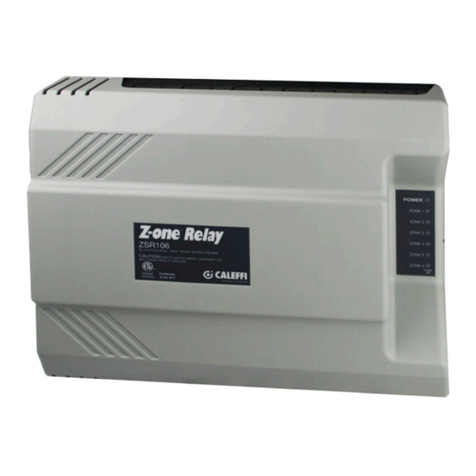
CALEFFI Z-one ZVR103 User manual

CALEFFI

CALEFFI Z-one ZVR103 User manual

CALEFFI 676 Series User manual

CALEFFI

CALEFFI 676 Series User manual

CALEFFI QuickSetter+ 132 Series User manual

CALEFFI

CALEFFI QuickSetter+ 132 Series User manual

CALEFFI 535H Series User guide

CALEFFI

CALEFFI 535H Series User guide

CALEFFI 146 Series Guide

CALEFFI

CALEFFI 146 Series Guide

CALEFFI TankMixer 520 Series User manual

CALEFFI

CALEFFI TankMixer 520 Series User manual

CALEFFI Z-one ZVR10 Series User manual

CALEFFI

CALEFFI Z-one ZVR10 Series User manual

CALEFFI 145 Series Guide

CALEFFI

CALEFFI 145 Series Guide

CALEFFI 528 Series User manual

CALEFFI

CALEFFI 528 Series User manual

CALEFFI 5335 Series User guide

CALEFFI

CALEFFI 5335 Series User guide

CALEFFI 642 Series User manual

CALEFFI

CALEFFI 642 Series User manual

CALEFFI 523160A Guide

CALEFFI

CALEFFI 523160A Guide

CALEFFI SATK Series User manual

CALEFFI

CALEFFI SATK Series User manual

CALEFFI FlowCal 121 Series User manual

CALEFFI

CALEFFI FlowCal 121 Series User manual

CALEFFI 5213TM series User guide

CALEFFI

CALEFFI 5213TM series User guide

CALEFFI Altecnic SATK40103 Guide

CALEFFI

CALEFFI Altecnic SATK40103 Guide

CALEFFI 513 Series User manual

CALEFFI

CALEFFI 513 Series User manual

CALEFFI LEGIOMIX 6000 series Guide

CALEFFI

CALEFFI LEGIOMIX 6000 series Guide

CALEFFI ThermoSetter 116 Series User manual

CALEFFI

CALEFFI ThermoSetter 116 Series User manual

CALEFFI QuickSetter+ 132 Series User manual

CALEFFI

CALEFFI QuickSetter+ 132 Series User manual

CALEFFI SinkMixer 521201A Guide

CALEFFI

CALEFFI SinkMixer 521201A Guide

CALEFFI 573 Series User manual

CALEFFI

CALEFFI 573 Series User manual

CALEFFI 311 Series User manual

CALEFFI

CALEFFI 311 Series User manual

Popular Control Unit manuals by other brands

Murata LBEE5PK2AE user manual

Murata

Murata LBEE5PK2AE user manual

Advantech USB-4711A user manual

Advantech

Advantech USB-4711A user manual

M-system R3-SV8B instruction manual

M-system

M-system R3-SV8B instruction manual

Panasonic KX-T7603X Service manual

Panasonic

Panasonic KX-T7603X Service manual

Singer Valve 206-RPS Installation, operating and maintenance instructions

Singer Valve

Singer Valve 206-RPS Installation, operating and maintenance instructions

Duco DucoBox Focus quick start

Duco

Duco DucoBox Focus quick start

Valcom V-2001A brochure

Valcom

Valcom V-2001A brochure

BERMAD 720 manual

BERMAD

BERMAD 720 manual

Cooper Notification SP4-RMX installation instructions

Cooper Notification

Cooper Notification SP4-RMX installation instructions

Red Valve 75 Series Installation, operation and maintenance manual

Red Valve

Red Valve 75 Series Installation, operation and maintenance manual

MG R3Y-YS4 instruction manual

MG

MG R3Y-YS4 instruction manual

Evoqua Wallace & Tiernan W3T170339 installation manual

Evoqua

Evoqua Wallace & Tiernan W3T170339 installation manual

GEM 687 operating instructions

GEM

GEM 687 operating instructions

Warner Electric CBC-200 Series Installation & operating instructions

Warner Electric

Warner Electric CBC-200 Series Installation & operating instructions

Panduit TX6A installation instructions

Panduit

Panduit TX6A installation instructions

Salus SPMV22 instruction manual

Salus

Salus SPMV22 instruction manual

Siemens LOGO! Series manual

Siemens

Siemens LOGO! Series manual

Harrington Signal HS-3200 Operator's manual

Harrington Signal

Harrington Signal HS-3200 Operator's manual

manuals.online logo
manuals.online logoBrands
  • About & Mission
  • Contact us
  • Privacy Policy
  • Terms and Conditions

Copyright 2025 Manuals.Online. All Rights Reserved.