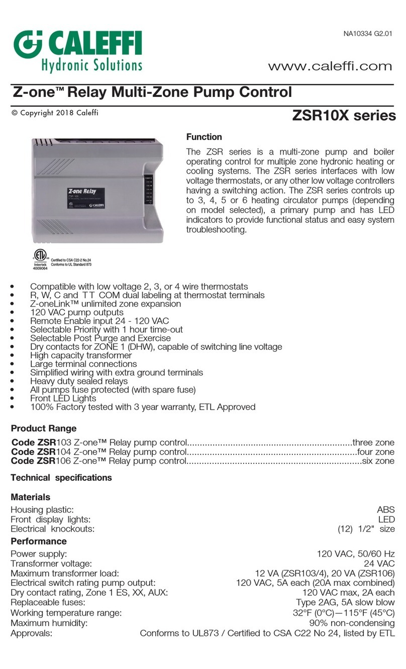
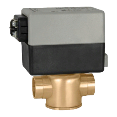
CALEFFI 152 Series User manual

Temperature regulating unit
for heating and cooling
series 152
Product range
Code 152650 Temperature regulating unit for heating and cooling with pump UPS 25-60
Code 152651 Temperature regulating unit for heating and cooling with pump UPS 25-80
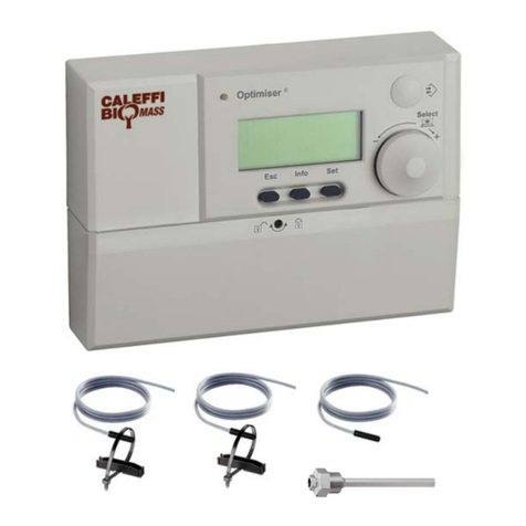
Code 151000 Room thermostat and indoor sensor
Technical specification
- Materials: - body: grey cast iron GG19
- hydraulic seals: EPDM
- insulation shell: PPM
- Mixing valve: 4-way
- Medium: water, glycol solutions
- Max percentage of glycol: 30%
- Working temperature range: 5÷60°C
- Max working pressure: 6 bar
- By-pass regulating range: 0,05÷0,5 bar
- Thermometer scale: 0÷60°C
- Primary and secondary circuit connections: 1” F with union
- Servomotor: electric supply: 230V 50 Hz
rating: 10 VA
cycle time: 240 s
torque: 10 N·m
- Grundfos pump: cod. 152650 model UPS 25-60
cod. 152651 model UPS 25-80
- Max ambient relative humidity: 95%
- Ambient temperature: 0÷40°C
- Protection class: IP 42
Head available at regulating unit connections
Power consumption
CALEFFI
01088/03 GB
Function
The temperature regulating unit is designed to guarantee the
correct contribution of heating energy required by the user, by
measuring the outside and room temperature values to regulate the
correct system flow temperature for either heating or cooling.
It is supplied complete with:
4-way mixing valve, servomotor, pump, flow temperature sensor,
outside temperature sensor, system temperature return sensor,
cooling surface humidity control sensor, temperature controller, flow
and return thermometers, unions for connecting to the primary and
secondary circuits, with preformed shell insulation.
The unit is designed for connection for remote data transmission.
This unit solves the problems of installation of regulating
components in modern small and medium-sized systems, due to its
compact size and ease of use.
The unit is factory set for use with underfloor heating systems.
6
5
4
3
2
1
0
H (m w.g.)
Q (m3/h)
6
5
4
3
2
1
06543210
H (m w.g.)
Q (m3/h)
1
2
3
1
2
3
UPS 25-60
code 152650
UPS 25-80
code 152651
6543210
3
2
1
0,45
0,30
0,17
100
65
35
1800
1100
700
I
(A) (W)
(rpm)
Pn
1,13
1,04
0,69
250
220
140
2450
1500
1000
Speed
I
(A) (W)
(rpm)
Pn
Speed
3
2
1

A
1"
B
142
C
78
A A
B
E
DC*
D
90
E
40
F
G
F
234
G
267
H
I
L
H
205
I
320
Code
152650/651
L
120
12
3
6
9
18
17
16
15
14
13
12
11
10
9
8
7
6
5
4
3
2
1
24
23
22
21
20
19
WATCH
CALEFFI
30
4050 60 7080
90 -25% +25%
-50% 0
22
2426 28 3032
34
Dimensions
Characteristic components
SYSTEM
FLOW
7
1
4
2
6
7
3
5
SYSTEM
RETURN
FLOW FROM
BOILER
BOILER
RETURN
16
18
20
22
24
CALEFFI
8
10
30
10
0
11
12
3
6
9
18
17
16
15
14
13
12
11
10
9
8
7
6
5
4
3
2
1
24
23
22
21
20
19
WATCH
CALEFFI
30
4050 60 7080
90 -25% +25%
-50% 0
22
2426 28 3032
34
20 20 10
60
30
10
0
20 20 10
60
9
12
➩
➩
➩
➩
01 4-way mixing valve.
02 Digital temperature controller for heating and cooling.
03Circulating pump:
code 152650 GRUNDFOS UPS 25-60
code 152651 GRUNDFOS UPS 25-80.
04Differential by-pass valve with graduated scale.
05 Flow temperature sensor.
06 Outside temperature sensor - connected via terminal.*
07Circuit flow and return thermometers in pockets.
08Connection point for remote transmission.
09 Limit control sensor for max relative humidity RH%.*
10 Room thermostat and indoor sensor (option for 152).*
11 Servomotor.
12 Return temperature sensor.
*Max length of sensor cable: 150 m.
12
3
6
9
18
17
16
15
14
13
12
11
10
9
8
7
6
5
4
3
2
1
24
23
22
21
20
19
WATC H
CALEFFI
30
4050 60 7080
90 -25% +25%
-50% 0
125 6 7
10
8
11
9
12
3 4
22
2426 28 3032
34
4-way mixing valve
Servomotor
Pump
Automatic by-pass
Differential by-pass
Thermometer
M
M
SR SF
BR BF
Hydraulic diagram
Temperature controller
The controller, which is normally installed on the unit, can also be
positioned remotely, following the electrical wiring scheme.

The front panel of the controller shows the following functions:
1) The LED is lit when there is a risk of condensation forming
in the cooling function (the mixing valve is closed).
In the heating function, this lights up intermittently during the
screed drying phase.
2) The LED is lit in the cooling function.
3) The LED is lit in the heating function.
4) Pump operating (ON): LED lit continuously.
5) Mixing valve closing: LED lit. The LED is lit continuously
when the controller is in the non-operative phase of
regulation, for example with TOutside between 18°C and 24°C
(see characteristic curve).
6) Mixing valve opening: LED lit.
7) Sensor malfunction: LED lit.
8) Function selector, 6 different functions possible:
a) Main controller off. In models where clock fitted, clock
remains on. The frost protection function remains active.
b) Controller operating in set-back mode.
Has no effect on the cooling function.
c) Controller operating in comfort mode.
Has no effect on the cooling function.
d) Controller in operation according to the cycles of the
comfort or set-back modes, determined by the two-channel
analogue clock, red indicator for heating times, blue indicator
for cooling times (item 13).
e)
Controller de-activated (pump ON - mixing valve ON).
This function guarantees heating to the maximum
temperature
value set on the printed circuit board (PCB).
Has no effect on the cooling function.
f) Summer function. Cooling is activated if required by the
ambient conditions (TOutside greater than the value set at
point 10) and dependant on the clock settings.This activation
takes place after ten minute if the outside temperature is more
than 1°C above the set value. With the exclusion of heating, the
frost protection function remains active.
Note:
Normally, with the clock programme, the changeover from
heating to cooling takes place after the outside temperature has
been higher than the set value for at least half an hour. This
selector position can therefore be used to effect a changeover
to cooling.
9) Temperature and characteristic curve selector. This
selector enables the user to input the maximum required
flow temperature, corresponding to the minimum
outside design temperature. Also enables optimisation of the
standard configuration set at the factory, allowing personal
control of the operation of the system.
If this value matches the setting on the main printed circuit
board (item 6 PCB), the regulation complies with the calculation
criteria given by the characteristic curve.
If this value is different from the setting on the main printed
circuit board (item 6 PCB) the controller will recalculate the new
characteristic curve. The maximum set temperature, however,
remains active. This selector also determines the characteristic
cooling curve, as it uses the inclination of the first line of the
curve, constructed for the heating (see characteristic curve graph).
10) Start or stop cooling selector. If the outside temperature
is higher than the set value, the cooling function is activated.
Factory setting: 24°C.
Characteristic curve
The characteristic curve is determined taking into account the
following parameters:
a) Max flow temperature set on controller (item 9 PCB).
Factory setting: 45°C.
b) Min flow temperature set on printed circuit board (item 5
PCB). Factory setting: 20°C.
c) Min outside temperature set on printed circuit board (item
1 PCB). Factory setting: -10°C.
d) Outside temperature limit for heating start in summer,
set on printed circuit board (item 3 PCB).
Factory setting: 18°C.
The characteristic curve has a straight line format.
In the example shown below, it has been calculated using the
factory set values.
Example of calculation of characteristic curve
X Axis - Outside temperature - TX
Y Axis - Flow temperature - TY
Calculation of minimum and maximum points
Point A: given by the intersection of Tmax X (18°C) and Tmin Y (20°C).
Point B: given by the intersection of Tmin X (-10°C) and Tmax Y (45°C).
Calculation of slope change points
Calculate the difference ∆X between Tmax X and Tmin X.
Thus: ∆X = 18 - (-10) = 28°C.
Calculate the difference ∆Y between Tmax Y and Tmin Y.
Thus: ∆Y = 45 - 20 = 25°C.
Points of change C and D of the curve are identified as follows:
Point C given by the intersection between:
X = Tmax X - 25% ∆X = 18 - 0,25 · 28 = 11°C
Y = Tmin Y + 55% ∆Y = 20 + 0,55 · 25 = 33,75°C
Point D given by the intersection between:
X = Tmax X - 50% ∆X = 18 - 0,5 · 28 = 4°C
Y = Tmin Y + 80% ∆Y = 20 + 0,8 · 25 = 40°C
Point E is the cooling starting point, whose characteristic curve has
the same slope as section A-C.
Point E given by the intersection between: TX = value set in item 10
(24°C) and TY = Tmin Y (20°C).
Characteristic curve
5
20
25
30
35
40
45
50
55
60
35 20 15 10 5 0 -5 -10 -15
TFLOW (°C)
TOUTSIDE (°C)
A (18;20)
C (11;33,75)
D (4;40)
B (-10;45)
80%
55%
50%
25%
15
10
2530
E (24;20)
Passive band

ON
12
DIP
34
11) Correction selector for comfort mode.
Range of adjustment from -25% to +25%.
Factory setting: correction = 0%.
The selector determines a parallel displacement of the
characteristic curve according to the new percentage value
selected in the comfort range (red indicator).
Example: if the selector is set to +25%, its effect on the flow
temperature will be as follows:
+25% ∆Y = 0,25 · 25 = 6,25°C.
The characteristic curve is then moved upwards by 6,25°C.
This has no effect on the cooling function.
Curve with comfort correction
12) Correction selector for set-back mode.
Range of adjustment from 0% to -50%.
Factory setting: correction = -25%.
The selector determines a parallel displacement of the
characteristic curve according to the new percentage value
selected in the set-back range (blue indicator).
Example: if the selector is set to -25%, its effect on the flow
temperature will be as follows:
-25% ∆Y = -0,25 · 25 = -6,25°C.
The characteristic curve is thus moved downwards by 6,25°C.
In addition, if, following this move, the flow temperature has to
be lower than the minimum heating start temperature (Tmin Y),
the following state will be obtained:
circulator OFF and mixing valve closed.
This has no effect on the cooling function.
Curve with set-back correction
13)
Daily or weekly analogue clock, used to select the heating and
cooling phases required with:
the red indicators for heating comfort and set-back and the blue
indicators to start and stop cooling.
Factory configuration: daily mode, minimum selection interval 15 min..
The changeover from daily to weekly mode, with a 60 min. minimum
selection interval, is carried out as follows:
raise the outer ring and move the
drive ring to the required position;
to do this, turn the pointer clockwise
until the innermost notch coincides
with one of the outer notches.
Reposition the outer ring, making
sure that the reference day shown
on it falls in the operating sector
of the switching point.
11) Printed circuit board
The surface of the printed circuit board (PCB) identifies the following
functions:
1) Minimum outside temperature (Tmin X), adjustable from -5°C
to -20°C, to which the set maximum flow temperature
corresponds (Tmax Y). Factory setting: -10°C.
2) Set-back mode exclusion selector, adjustable from
0°C to -20°C. Factory setting: -15°C.
If the outside temperature falls below the set value, the heating
is reactivated according to the characteristic curve of the
comfort mode.
3) Maximum outside temperature to start heating, or summer
limit, (Tmax X), adjustable from 14°C to 22°C.
Factory setting: 18°C.
An outside temperature higher than the set value will cause the
following state: circulator OFF and mixing valve closed. An outside
temperature 4°C higher than the set value will cause activation of
the cooling, if this outside temperature is greater than the value set
on the front panel, item 10. - e.g.: T
o
set on front panel=24°C, T
o
set
on PCB=22°C.
Activation will take place at To=26°C (22+4).
4) Selection microswitch for screed setting drying program.
Factory setting: OFF (1234).
This program is used for carrying out correct drying of the
screed, above which the final flooring will be laid (its activation
excludes all other functions).
The program has a duration of seven days: during the first three
days, the flow temperature is maintained at 25°C, whilst for the
remaining four days, the flow temperature is raised and maintained
at the maximum temperature value set at point 9 on the front panel.
The activation of this program is displyed by the flashing LED
on the front panel, point 1.
The frequency of flashing indicates the number of drying days
which have passed: one pulse every 8 seconds indicates
day 1, two pulses every 8 seconds indicates day 2, etc. If the
electricity has to be switched off in this phase, the controller will
start its drying cycle again from the beginning. The front panel
LED, point 1, continuously lit, indicates the end of the drying
program. At this point the microswitch should be turned to OFF.
Note: In manual mode the screed drying procedure cannot
be
activated.
When cooling, this series of microswitches has the function of
limiting the minimum temperature transmitted to the panel. This
minimum temperature depends on the characteristics of the
system and the type of air conditioning adopted. The different
activation configurations are shown below.
Factory configuration: 16°C.
15
20
25
30
35
40
45
50
55
60
25 20 15 10 5 0 -5 -10 -15
TFLOW (°C)
TOUTSIDE (°C)
6,25°C
15
20
25
30
35
40
45
50
55
60
25 20 15 10 5 0 -5 -10 -15
TFLOW (°C)
TOUTSIDE (°C)
6,25°C
12
6
93
1
13
2
14
3
15
4
16
5
17
6
18
7
19
8
20
9
21
10
22
11
23
12
24
-7 d
5 7
3
1
13
2 6 8
12
11
4
10
14
9 18
4(2)A
4(2)A
4(2)A
KA
KA
MA
PS
A
B
N
L
LP
MC
C
F
DIGITAL
REGULATOR
4(2)A
4(2)A
OPEN
CLOSED
T 40
tTyp 2125
N
L230V AC
4VA
INLET PUMP
MIXINGVALVE 230V AC
10A max
PUMP
N
ROOM
THERMOSTAT
2501
TA1
TA
X
SE
SM
UR
0 100
RF(%)
50
20 40
30
35 65
65
55
max
1,5 6
3 4,5
NZ
-5 -20
-10 -15
-20 0
-10
14 22
18
OPEN
CLOSED SR
ON
12
DIP
34
15
16
17
ON
12
DIP
34
ON
12
DIP
34
ON
12
DIP
34
Screed
drying
Free flow
temperature
Flow temperature
limited 16°C
ON
12
DIP
34
ON
12
DIP
34
ON
12
DIP
34
Flow temperature
limited 14°C
Flow temperature
limited 12°C
Flow temperature
limited 10°C

5) Selector for minimum flow temperature at heating start-up
(Tmin Y).
Adjustable from 20°C to 40°C.
Factory setting: 20°C.
6) Maximum limit temperature selector.
Adjustable from 35°C to 65°C.
Factory setting: 50°C
In case a higher value has been set at point 7 of the front panel,
this will be restricted to the limit value.
7) NZ Neutral zone regulation selector.
Adjustable from 1,5°C to 6°C.
Factory setting: 2°C (equivalent to ±1°C).
If the flow temperature variation remains within the temperature
value selected in the neutral zone, the mixing valve remains
inactive.
When cooling, the neutral zone automatically takes the value 1,5°C.
8) RF(%) Return sensor regulation selector.
Adjustable from 0% to 100%.
Factory setting: 80%.
This selector is used to optimise the system output according to
the difference in temperature between flow and return (∆T).
∆T is calculated as a percentage of the flow temperature
calculated on the characteristic curve.
∆TY = (Tflow set Y-Tmin Y)
∆T = ∆TY · %set · 0,3.
Treturn set Y = Tflow set Y - ∆T.
Example with factory setting values:
flow temperature calculated on the characteristic curve,
Tflow set Y = 40°C (project conditions).
Thus:
∆TY = (40 - 20) = 20°C
∆T = 20 · 0,8 · 0,3 = 4,8°C
Treturn set Y = 40 - 4,8 = 35,2°C.
If the return temperature measured (Treturn Y) is ≠Treturn
set Y, the controller will modify the characteristic curve, moving
it upwards or downwards, to move the return temperature to the
set value.
This continuous comparison prevents room overheating caused
by gratuitous heat sources modifying the heating load.
There is no effect on the cooling function.
Curve with return temperature regulation
9) Auxiliary contact. This contact opens when the mixing valve is
completely closed to the secondary and open to the primary.
It can be used to shut down the pump of the primary circuit or
the boiler.
10) UR Relative humidity sensor wiring. This sensor is used to
detect the limiting value of relative humidity to prevent
condensation on the cooling surface.
This is calibrated for RH= 80÷85%. When the calibrated value
is reached, this will cause the following state: mixing valve
closed, pump ON.
If various zones at risk of condensation are to be controlled, the
humidity sensor must be connected to a suitable interface kit
(transformer, converter and humidity sensor). Up to 12 converters
plus sensor can be connected to a single transformer.
Humidity sensor control
At the start of each cooling season, the operating condition of the
sensor should be checked by placing a damp pad on its surface;
this operation should cause the mixing valve to close and the yellow
LED, point 1 on the front panel, to light.
Positioning humidity sensor
The umidity sensor must be positioned at the point where there is
most risk of the formation of condensation, depending on the
characteristics of the system. It must be positioned with the printed
part upward, according to the diagrams shown below.
Fix ends E, taking care that the central part adheres perfectly to the
manifold or to the piping.
Layouts for the correct positioning of the max RH% limit sensor.
The sensor should be
fixed to the manifold
installed in the position
where the RH% relative
humidity value has not
to exceed the safety
limits. Fixing in ensured
by inserting the two
straps contained in the
package through the
suitable holes on the
sensor.
15
20
25
30
35
40
45
50
55
60
25 20 15 10 5 0 -5 -10 -15
TFLOW (°C)
TOUTSIDE (°C)
Treturn 35,2°C
LH side
terminal strip
01
N
L
UR
SENSOR RH%
code 150050
SENSOR RH%
code 150050
123456
CONVERTER
code 150051
TRANSFORMER
code 150052
24 V220 V
SR
Upper side: printed circuit
Lower side: sited on the cooling surface
E E

N.B.: When installing the RH% limit sensor according to the
diagrams, as indicated, possible formation of condensation on the
surface. In areas where the max RH% limit sensor is installed,
adequate ventilation must always be present.
11) SE Outside sensor wiring. Connect the outside sensor using
2-core cable (2x0,75) to the connector provided on the unit.
12) SR Return sensor wiring. Factory fitted.
13) TA1 Room thermostat wiring. Optional.
14) Pump shut-down variant. Sometimes the temperature
regulating unit is installed in a system where there may be
one or more users with different usage requirements. In this case,
for users requiring ON/OFF operation, it may be necessary to
shut down the unit circulator.
The electrical diagram shown below illustrates this possibility;
the user auxiliary contact must be inserted in series with the
normal wiring.
15) SM Flow sensor wiring. Factory fitted.
16) CSummer - winter circuit changeover valve wiring.
FThis connection enables the 3-way valve to be activated
automatically for hydraulic deviation between the boiler circuit
and the chiller circuit. This takes place after the outside
temperature has risen above the value set at point 10 for at least
half an hour.
Ten minutes later, the regulating unit pump is activated.
17) KA Chiller activation wiring. This activation takes place in the
same way as in point 16.
18) Remote data transmission connector.
Table of sensor resistance values*
*excluding max RH% limit sensor
Safety
If the flow or outside sensor shows an ohm resistance value outside
its working range (damaged or disconnected sensor), the following
operating state is automatically activated:
Pump OFF, Mixing valve OFF, LED 7 continuously lit.
Safety thermostat code 622001
Additional for use with underfloor heating systems.
- Range of adjustment: 5 ÷ 55°C
- Factory setting: 50°C
- Protection class: IP 40
- Contacts load: (C-1) 10(2,5)A / 250V
- Contacts load: (C-2) 1(1)A / 250V
PS
MA
MC
Brown
RH side
terminal strip
Pump shut-down wiring
Unit 152 pump
User auxiliary contact
6
7
8Pump shut-down variant
°C Ohm
-15 11.382
-12 9.912
-10 8.933
-6 7.439
-3 6.492
-2 6.206
05.632
°C Ohm
05.632
25.187
44.742
64.347
84.000
10 3.553
15 2.971
°C Ohm
20 2.431
25 2.000
30 1.655
35 1.376
40 1.150
45 966
50 815
°C Ohm
55 690
60 587
65 501
70 430
75 370
80 319
85 276
°C Ohm
90 240
95 209
100 183
SE
SE
LH side
terminal strip
Outside sensor
Connecting
wiring Connector
C1
2
+°C
KA
RH side
terminal strip
KA
C
FMN
Boiler circuit open
Chiller circuit open
12
3
6
9
18
17
16
15
14
13
12
11
10
9
8
7
6
5
4
3
2
1
24
23
22
21
20
19
WATCH
CALEFFI
30
405060 7080
90-25% +25%
-50% 0
22
242628 3032
34
The maximum heat energy that the panel can produce in relation
with the climate values recorded, can be reached by controlling the
below outlined parameters.
-Minimum flow temperature on the characteristic curve, which can
be selected through the microswitch (point 4 on the back panel).
-Sensor (code 150050) controlled maximum RH% limit.
-
Room temperature controlled through room thermostat (code 151000).
-Room temperature and relative humidity controlled through a
dedicated fan-coil).

Example of safety thermostat application on system low
temperature branch circuit
Frost protection function
When the selector, point 6 on the front panel, is positioned
to or ,
there are two types of intervention:
a) If the flow temperature is below 7°C, the controller activates the
operation of the unit until a flow temperature of 20°C is reached.
When this value is reached, it will return to the inactive status.
b) If the outside temperature is below 5°C (+2 -0), the controller
keeps the pump running.
Anti-seize function
If the pump remains inactive for twenty four hours, the following
program automatically comes into operation, with:
mixing valve open for 30 seconds,
mixing valve closed for 30 seconds,
pump ON for 60 seconds.
When this function is operating, it cannot be interrupted.
Manual control
To carry out adjustment:
-Remove the servomotor fixing screws.
-Lift the servomotor. This gives access
to the control knob.
Refer to the information given on
the knob itself.
Options
Room thermostat, code 151000.
The regulating unit can be
supplemented with a room
thermostat, able to adjust the
value of the flow temperature
according to the actual room
temperature. This configuration
makes it possible to take account
of gratuitous heat gains, by
refining the value of the flow
temperature, with optimum results
in terms of comfort and energy
saving. In cooling conditions, the
setting on the thermostat should
be increased by 2°C.
Operation of the room thermostat
The room thermostat makes it possible to optimise the operation of
the system, as it modifies the regulating curve automatically.
Depending on the time periods for comfort and set-back selected
on the clock and the room temperature setting, it will read the actual
room temperature. On the basis of this parameter, it will make any
necessary modification to the characteristic curve (A) for the
purpose of accelerating operation and preventing excessive
heating or cooling of the room.
The difference between the actual room temperature measured by
the thermostat and the set temperature produces an amplified
effect in relation to that produced by a similar variation in the
outside temperature.
A difference of 1°C in the room temperature causes a move of the
characterisitc curve equal to 7°C of the outside temperature, with
the corresponding variation in flow temperature.
For example, if Troom set = 20°C and Troom measured = 19°C, than the
difference of 1°C will cause a movement of the characteristic curve
of 7°C towards the left (B). The flow temperature will consequently
be raised. In the case of a negative difference, the movement will
take place on the curve C.
This behaviour is applicable for a maximum difference of 3°C in the
room temperature.
In addition, the maximum temperature limit set at item 6 on the PCB
remains active.
In the set-back band, the set room temperature is automatically
reduced by 2°C, thus defining Tset set-back.
This reduction will cause a move to the right of the characteristic
curve, equating to 14°C of the outside temperature (D), with a
corresponding variation in flow temperature.
Whenever the measured room temperature falls below
Tset set-back,
the initial characteristic curve (A) will be restored with the set-back
correction set at point 12 on the front panel.
Curve with room thermostat regulation
Room thermostat electrical connection
Install the room thermostat and connect by sheathed 2-core cable
(2x0,75) to the terminal strip of the regulator PCB, as shown in the
diagram below.
WARNING - if the connecting cable between the thermostat
and the control unit is not sheathed, it must be run in its own
ducting.
The maximum length is 150 m.
A
uf
O
p
e
n
O
uv
ri
r
V
o
r
l
au
f
t
e
m
p
e
r
a
t
u
r
f
ü
r
F
u
ß
b
o
d
e
n
h
ei
zu
n
g
b
ea
c
ht
e
n
B
ei
p
a
ss
ni
c
h
t
v
o
n
H
a
n
d
sc
h
li
e
ß
e
n
M
i
s
c
h
e
r
Z
u
C
lo
s
e
F
e
r
m
é
16
18
20
22
24
CALEFFI
10
20
25
30
35
40
45
50
55
60
25 20 15 10 5 0 -5 -10 -15
TFLOW (°C)
TOUTSIDE (°C)
15
BA C D
TA 1
LH side
terminal strip
Room thermostat
TA1
TA TA
12
3
6
9
18
17
16
15
14
13
12
11
10
9
8
7
6
5
4
3
2
1
24
23
22
21
20
19
WATCH
CALEFFI
30
4050 60 7080
90-25% +25%
-50% 0
22
2426 28 3032
34

Temperature regulating unit for heating and cooling. Connections 1" F with unions. Body in grey cast iron GG19.
Hydraulic seals in EPDM. Maximum working pressure 6 bar. Ambient temperature from 0 to 40°C. Regulating
temperature from 5 to 60°C (factory settings: heating 45°C, cooling 16°C). Maximum ambient relative humidity 95%.
Consisting of: 4-way mixing valve; mixing valve servomotor with the following characteristics: power supply 230 V
50 Hz, rating 10 VA, cycle time 240 s, torque 10 N·m. Pump UPS 25-60. By-pass valve with regulating scale
from 0,05 to 0,5 bar. Temperature controller with two channel clock, for daily/weekly programming. Flow
temperature sensor. Return temperature sensor. Outside temperature sensor, connectable to terminal.
Maximum RH% limit control sensor. Flow and return pocket thermometers, scale 0÷60°C. Automatic
summer/winter cycle changeover. Provided with connection for remote data transmission. Protection
class IP 42. Complete with PPM insulation.
SPECIFICATION SUMMARIES
Code 152650
Temperature regulating unit for heating and cooling. Connections 1" F with unions. Body in grey cast iron GG19.
Hydraulic seals in EPDM. Maximum working pressure 6 bar. Ambient temperature from 0 to 40°C. Regulating
temperature from 5 to 60°C (factory settings: heating 45°C, cooling 16°C). Maximum ambient relative humidity 95%.
Consisting of: 4-way mixing valve; mixing valve servomotor with the following characteristics: power supply 230 V
50 Hz, rating 10 VA, cycle time 240 s, torque 10 N·m. Pump UPS 25-80. By-pass valve with regulating scale from 0,05
channel clock, for daily/weekly programming. Flow temperature sensor. Return temperature sensor. Outside
temperature sensor, connectable to terminal. Maximum RH% limit control sensor. Flow and return pocket
thermometers, scale 0÷60°C. Automatic summer/winter cycle changeover. Provided with connection for remote
data transmission. Protection class IP 42. Complete with PPM insulation.
Code 152651
Room thermostat and indoor sensor for temperature regulating unit.
Code 151000
Application diagram
CALEFFI CALEFFI
CALEFFI CALEFFI
PN10
CALEFFI
CALEFFI
10
0
8
6
4
2
10
0
8
6
4
2
10
0
8
6
4
2
10
0
8
6
4
2
10
0
8
6
4
2
10
0
8
6
4
2
10
0
8
6
4
2
10
0
8
6
4
2
10
0
8
6
4
2
10
0
8
6
4
2
PN10
CALEFFI
CALEFFI
10
0
8
6
4
2
10
0
8
6
4
2
10
0
8
6
4
2
10
0
8
6
4
2
10
0
8
6
4
2
10
0
8
6
4
2
10
0
8
6
4
2
10
0
8
6
4
2
10
0
8
6
4
2
10
0
8
6
4
2
12
3
6
9
18
17
16
15
14
13
12
11
10
9
8
7
6
5
4
3
2
1
24
23
22
21
20
19
WATCH
CALEFFI
30
405060 7080
90-25% +25%
-50% 0
22
242628 3032
34
10
0
8
6
4
2
10
0
8
6
4
2
10
0
8
6
4
2
10
0
8
6
4
2
10
0
8
6
4
2
10
0
8
6
4
2
10
0
8
6
4
2
10
0
8
6
4
2
10
0
8
6
4
2
10
0
8
6
4
2
10
0
8
6
4
2
10
0
8
6
4
2
10
0
8
6
4
2
10
0
8
6
4
2
10
0
8
6
4
2
10
0
8
6
4
2
We reserve the right to change our products and their relevant technical data, contained in this publication, at any time and without prior notice.
CALEFFI S.P.A. · I· 28010 FONTANETO D’AGOGNA (NO) · S.R. 229, N.25 ·TEL.INT. +39 0322 8491 R.A. ·FAX +39 0322 863723
· Http://www.caleffi.com ·E-mail: info@caleffi.it ·
CALEFFI
This manual suits for next models
2
Other CALEFFI Controllers manuals
Popular Controllers manuals by other brands

Taco
Taco iWorx UCP-1 Application guide

MicroImage Video Systems
MicroImage Video Systems PX101EX Operation manual

Simplex
Simplex TrueCom 5140-9243 quick start guide

Evco
Evco RICS 4.30 user manual

Rotork Fairchild
Rotork Fairchild PAX1 user manual

Greenheck
Greenheck MP-210 Installation, operation and maintenance manual

OJ
OJ ETO2 user manual

United Technologies
United Technologies Carrier OPN-VAVB1 Installation and startup guide

Edwards
Edwards ASG2-1000-1/8 NPT instruction manual

Charles
Charles E1 installation guide

PIETRO FIORENTINI
PIETRO FIORENTINI REVAL 182 Technical manual

DROPSA
DROPSA ADVANCED LUBRICATION CONTROLLER INSTRUCTION AND PRODUCT DATA SHEET