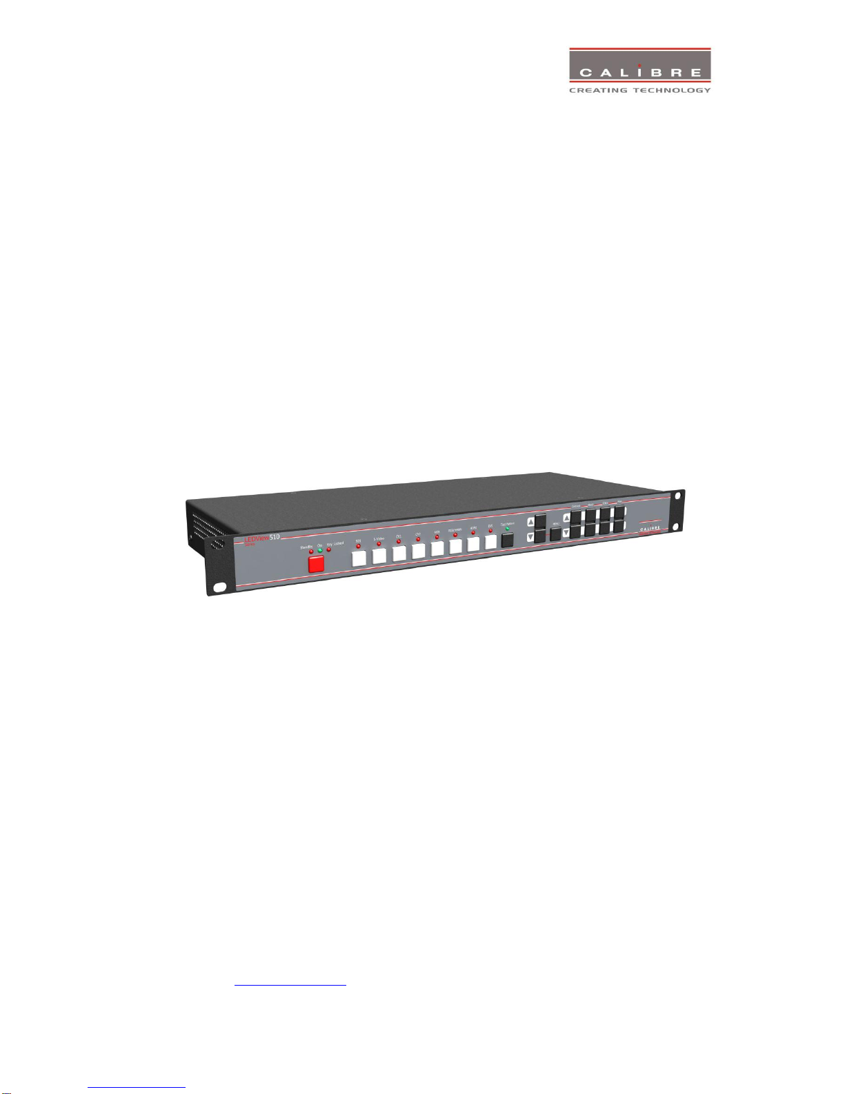
General Introduction
LEDView-510/530 is a very flexible image scaler developed specifically for driving large screen
displays such as LED walls and multiple screen applications from video or graphics sources.
LEDView-510/530 features state of the art digital image processor which provides market leading HD&
SD per-pixel multiple Iow-angle motion-adaptive de-interlacing and automatic film pull-down correction
for 3:2 and 2:2, significantly outperforming the capabilities of benchmark competitor products.
LEDView-510/530 features excellent image processing algorithms for the very best scaling, film and
video noise reduction and MPEG artefact reduction.
LEDView-510/530 uses a very flexible high performance video input front end including true
component video support in analog YPbPr and RGBS formats and 3GSDI/HDSDI/SDI digital formats
as well as composite (CVBS) and YC/S-Video inputs. A very high performance video decoder is
utilised with 4x oversampling and 3D Y/C separation for outstanding video image clarity. HDMI and
DVI video with HDCP encryption is also supported, as are computer graphics inputs in SVGA analogue
and HDMI/DVI digital formats.
The output format can be set to I/O Lock mode where it locks the output frame rate to the input frame
rate dynamically without frame rate conversion so as to reduce system latency, or it can be set to a
fixed output frame rate for driving basic screens which are not 50Hz-compatible. A Low latency mode
with non-motion adaptive reduced processing is available to further reduce latency. The output format
can also be set to lock to an externally provided synchronization signal.
Outputs are available in VGA analog and DVI digital formats as well as 3GSDI serial digital formats
which are useable simultaneously so that one output can drive the screen while the other runs a local
monitor. Note that not all PC output formats are supported by 3GSDI standards in which case the
3GSDI output is disabled. Also note that if an HDCP encrypted signal is connected to the HDMI or DVI
input, the DVI output signal will be similarly HDCP encrypted and the VGA analog output as well as the
3GSDI output will be disabled.
Interlaced outputs are supported and can be run through a vertical temporal filter greatly reducing
interlace flicker.
LEDView-510/530 supports Zoom, Pan and Tilt to select a part of the input image, fill the screen and
pan within it.
LEDView-510/530 is targeted to drive LED screens and provides output window size control down to fit
a single LED module at 128x96 pixels. The output window can be positioned anywhere within the
chosen output resolution.
LEDView-510/530 can also be operated in a mode to drive a projector, in which case warp features
become available allowing to adjust the image to match a rotated, tilted or curved screen.
LEDView-510/530 is designed for multi screen or multi projector installations. Auto Zoom and Edge
Blend with elaborate Black Level Uplift is provided to stitch multiple projector images together. The
same stitching is available to support LED walls which exceed the maximum output resolution of
1920x1200 pixels of a single LEDView-510/530. Edge Blend allows to electronically reduce the
brightness level of certain image regions to match the brightness of overlapping areas. Auto Zoom
automatically crops and zooms the input video image to display the section of the total image on the
corresponding projector or screen.
System control is via an OSD controlled by keys on the front panel or through the inbuilt TCP/IP web
server. The OSD is scaled to fit the chosen window. At extreme shrink it is hardly readable and control
from a web browser is recommended. In fact, in most LED screen applications control through a web
browser is the primary method of changing the unit set up. LEDView-530 also features a front panel
LCD menu and a jog wheel instead of keys for easier and faster set-up.