Calix E5-121/MNLC RT-410 User manual

Calix E5-121 / MNLC RT-410
Retrofit Kit Installation Guide
January 2009
#220-00260, Rev. 10


Proprietary Information: Not for use or disclosure except by written agreement with Calix.
© 2001-2009 Calix. All Rights Reserved.
Contents
About This Guide.......................................................................... 5
Chapter 1: Installation Overview................................................. 7
About E5-121/MNLC RT-410 Retrofits........................................................................... 8
Installation Process Overview..................................................................................... 10
Retrofit Kit ..................................................................................................................... 11
User-Supplied Items..................................................................................................... 12
Chapter 2: Preparing the Cabinet for the Retrofit ................... 13
Removing a USAM Shelf.............................................................................................. 14
Installing Subscriber Interface Adapter Cables ......................................................... 17
Chapter 3: Installing the E5-121 Retrofit Kit ............................ 19
Installing the DC Power System.................................................................................. 20
Installing the Fan Tray ................................................................................................. 22
Installing Converter Modules ...................................................................................... 23
Installing the E5-121 Service Unit(s) ........................................................................... 24
Connecting Interface Cables to the E5-121 Unit(s).................................................... 26
Turning Up the System ................................................................................................ 28

4
Proprietary Information: Not for use or disclosure except by written agreement with Calix.
© 2001-2009 Calix. All Rights Reserved.

5
Proprietary Information: Not for use or disclosure except by written agreement with Calix.
© 2001-2009 Calix. All Rights Reserved.
About This Guide
This document provides a general practice for installing a Calix E5-121 retrofit kit into a
Motorola/Next Level Communications (MNLC) RT-410 outdoor cabinet.
Installing the E5-121/MNLC RT-410 retrofit kit may require removal of some native
equipment from the cabinet, depending on the configuration.
Intended audience
This document is intended for use by network and outside plant engineers, CO technicians,
field support personnel, and other craft personnel responsible for equipment installation and
cabling. Familiarity with standard telecom and datacom terminology and practices, as well as
standards-based DSL and Ethernet technologies and conventions, is recommended.
Related documentation
You can access the complete set of Calix E5-121 user documentation from the Calix
Customer Center, accessible online at www.calix.com.
Safety Notices
DANGER! RISK OF ELECTRIC SHOCK. All OSP cabinets contain
HAZARDOUS VOLTAGES. Carefully follow national and local codes when
working with power.
WARNING! This installation practice requires substantial knowledge of
Outside Plant (OSP) cabinet elements and equipment. Only qualified
technicians should perform the tasks described in this document. Read and
understand all procedures before performing.
DANGER! CLASS 1 LASER PRODUCT. INVISIBLE LASER RADIATION
MAY BE PRESENT. Fiber optic radiation can cause severe eye damage or
blindness. Do not look into the open end of an optical fiber.
ALERT! Before starting installation activities, notify the local carrier Central
Office (CO) to report entry into the cabinet.
ESD ALERT! Beware of Electrostatic Discharge (ESD). Some equipment
covered in this document may be subject to damage from ESD. Follow
standard ESD precautions to protect yourself and avoid damaging the
electronic equipment.

6
Proprietary Information: Not for use or disclosure except by written agreement with Calix.
© 2001-2009 Calix. All Rights Reserved.

Proprietary Information: Not for use or disclosure except by written agreement with Calix.
© 2001-2009 Calix. All Rights Reserved.
Chapter 1
Installation Overview
This chapter describes the Calix E5-121/MNLC RT-410 retrofit kit and provides an
overview of the installation process.
Topics Covered
This chapter covers the following topics:
A description of the E5-121/MNLC RT-410 retrofit solution
An overview of the installation process (flow chart)
A list of components and parts supplied with the retrofit kit
A list of required, user-supplied items

8
Proprietary Information: Not for use or disclosure except by written agreement with Calix.
© 2001-2009 Calix. All Rights Reserved.
About E5-121/MNLC RT-410 Retrofits
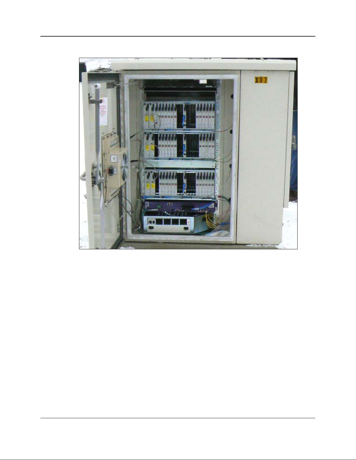
This document describes how to install a custom Calix E5-121 retrofit kit into a Motorola/
Next Level Communications (MNLC) RT-410 outdoor cabinet.
Overview
MNLC RT-410 cabinets are equipped with up to four native USAM shelves and are supplied
by remote power (line power). The Calix retrofit kit re-uses the existing USAM line power
input pairs, aggregating them to a new DC power system, which in turn supplies standard
-48 VDC power to the Calix E5-121 service unit(s).
The retrofit kit supports up to four E5-121 units, generally in a 1:1 relationship to the USAM
shelves, where you must remove a USAM shelf for each E5-121 unit you install. In cabinets
equipped with three or fewer USAM shelves, you can install the retrofit kit and one E5-121
unit without removing any native equipment. For cabinets equipped with the maximum four
USAM shelves, installing the retrofit kit requires removal of at least one USAM shelf.
The retrofit kit consists primarily of the DC power system and related cabling. The retrofit
kit does not include other components required for installation. These items are ordered and
packaged separately, but installed together with the kit:
Converter modules (±190 to -48 VDC)
Fan tray for DC converter shelf
Subscriber interface adapter cables, MS2to RJ-21 (CAT5, CAT3 options)
Calix E5-121 service unit(s)
Installing the retrofit kit will affect subscriber services (if present) on any removed USAM
equipment. Therefore, Calix recommends performing the installation during a standard
maintenance window.
Guidelines
Follow these general guidelines for retrofit kit installation:
The MNLC RT-410 retrofit kit supports up to (4) E5-121 service units (not included).
Expect to remove (1) USAM shelf for each Calix E5-121 unit to install.
Use the remote power calculator tool (available on the Calix Resource Center) to
determine your line powering requirements, including the number of required power
pairs and converter modules.
Use extreme caution when working with remote power. Never assume that power on the
input lines is off.
Installing the retrofit kit may be a service-affecting procedure. Perform installation during
a standard maintenance window.

9
Proprietary Information: Not for use or disclosure except by written agreement with Calix.
© 2001-2009 Calix. All Rights Reserved.
RT-410 Cabinet with Retrofit Kit Installed

10
Proprietary Information: Not for use or disclosure except by written agreement with Calix.
© 2001-2009 Calix. All Rights Reserved.
Installation Process Overview
The retrofit kit installation process involves the following high-level steps:

11
Proprietary Information: Not for use or disclosure except by written agreement with Calix.
© 2001-2009 Calix. All Rights Reserved.
Retrofit Kit
Before you begin the installation, check to verify that your retrofit kit contains all of the
items listed below.
Qty Item Description
1 DC power & distribution assembly:
19" mounting panel
Integrated LP 2500D downstream power converter shelf
Integrated DC distribution with 12 GMT fuse-protected positions
Integrated fan tray housing
Note: The power assembly is pre-terminated with cables that interface
with cabinet systems and other equipment not included in the kit:
Ground cable (connect to cabinet main ground bar)
Power input cable (connect to USAM line power supply cables)
E5-121 power cable (connect to Calix E5-121 units)
4 Hex head mounting screws, self-tapping (#12-24 x 5/8")
11 5A GMT fuse (distribution to E5-121 units)
1 1A GMT fuse (distribution to fan tray)
The following items are not included in the kit, but are required to complete the retrofit
installation.
Qty Item Description
1 Fan tray for DC converter shelf
up to
10
LP ±190 to -48 VDC converter modules
up to
4
Subscriber interface cables, MS2to RJ-21 (CAT5 or CAT3 options)
up to
4
Calix E5-121 service units

12
Proprietary Information: Not for use or disclosure except by written agreement with Calix.
© 2001-2009 Calix. All Rights Reserved.
User-Supplied Items
The following user-supplied items are required for installation.
Tools and equipment
Bring the following tools and equipment to the installation site:
Power drill with universal drill, socket, and screwdriver bits
Socket wrench/nut driver set (standard)
Screwdriver set (standard)
Wire stripper
Tie-wrap cutter
Compression crimping tool
Comb tool MS2connectors
MS2connector mating tool
Digital multi-meter
Materials
Bring the following materials to the installation site:
Electrical tape
Cleaning towels, icky-pick wipes
Cable ties (tie-wraps)
Fiber jumpers (SC-to-LC)
Fiber bulkhead adapters (SC)

Proprietary Information: Not for use or disclosure except by written agreement with Calix.
© 2001-2009 Calix. All Rights Reserved.
Chapter 2
Preparing the Cabinet for the Retrofit
Before installing the Calix E5-121 retrofit kit, you must prepare the MNLC RT-410 cabinet
for an equipment retrofit. Preparatory tasks include removing one or more native USAM
shelves (if required) and installing subscriber interface adapter cables. This chapter describes
how to perform the preparatory tasks.
Topics Covered
This chapter covers the following topics:
Removing native USAM shelves from the cabinet
Installing subscriber interface adapter cables

14
Proprietary Information: Not for use or disclosure except by written agreement with Calix.
© 2001-2009 Calix. All Rights Reserved.
Removing a USAM Shelf
If the MNLC RT-410 cabinet is equipped with four USAM shelves, you must remove at least
one USAM shelf to provide room for the retrofit kit. Remove USAM #4 first (bottom
position on the rack). For cabinets equipped with fewer than four USAM shelves, you can
install the kit and one E5-121 unit without removing any native equipment.
If you are installing more than one E5-121 unit with the retrofit, you must remove additional
USAM shelves on a 1:1 basis (that is, remove one USAM shelf for each additional E5-121
unit you are installing, up to a total of 4 units).
ALERT! Service-Affecting Procedure. Removing a USAM shelf will affect
services present on that shelf. Relocate services to another shelf as
required, or perform this task during a maintenance window.
To remove a USAM shelf
1. Open the cabinet's front door. Pull the plunger on the door alarm switch to disable alarm
reporting while you are working on the cabinet.
2. Locate the USAM shelf to remove. For example, locate USAM shelf #4 (if present),
mounted in the bottom position on the rack.
3. At the identified USAM shelf, disconnect fiber(s) from the control card(s), if present.
Note: Keep the disconnected fibers in place near the rack, to connect to the E5-121
once installed. Re-using the fibers requires SC-to-LC fiber jumpers with SC bulkhead
adapters.

15
Proprietary Information: Not for use or disclosure except by written agreement with Calix.
© 2001-2009 Calix. All Rights Reserved.
4. At the identified USAM shelf, disconnect the power input cables from the PSA and PSB
power cards.
Note: Keep the disconnected power input cables in place near the rack, to connect to the
new DC power system once installed.
5. Remove all plug-in cards from the USAM shelf. Pack the cards into clamshells (if
available) and into a box for transport or storage.
6. Remove the identified USAM shelf from the rack as follows:
a. Unscrew its (4) mounting screws and pull the USAM shelf forward, away from the
rack. Set the USAM shelf on the ground (face down), or allow the shelf temporarily
hang from the attached subscriber cabling.
b. Behind the removed USAM shelf, trace its subscriber cabling back to the MS2
connectors (interfacing to the protection panels).

16
Proprietary Information: Not for use or disclosure except by written agreement with Calix.
© 2001-2009 Calix. All Rights Reserved.
c. Disconnect the mated MS2connections for each 25-pair subscriber cable (4x).
d. Disconnect the chassis ground (lug) from the left rear corner of the USAM shelf.
Note: Leave the ground cable in place near the rack, to connect to the E5-121 once
installed.
e. Disconnect any additional cabling from the rear of the USAM shelf, including the
Ethernet management and Test Out cables, if present.
f. Completely remove the USAM shelf from the cabinet and pack it into a box for
transport or storage.
7. Repeat the steps above to remove additional USAM shelves, as required. Remove shelves
from lowest to highest on the rack.
Note: Set aside boxes containing the removed equipment (USAM shelves, cards) for return
to the office.

17
Proprietary Information: Not for use or disclosure except by written agreement with Calix.
© 2001-2009 Calix. All Rights Reserved.
Installing Subscriber Interface Adapter Cables
USAM shelves each interface with the cabinet's line protection system using (4) 25-pair
subscriber cables with MS2connectors. After USAM shelf #4 is removed, you can re-use its
protector panel cabling to provide the subscriber interface for the new E5-121 equipment.
You must install adapter cables (MS2to RJ-21) to connect the existing protection panel
cabling to the E5-121. Install one 25-pair adapter cable per each E5-121 unit to install.
To install the subscriber interface adapter cable(s)
1. Get the MS2to RJ-21 subscriber interface adapter cable(s) from the kit.
2. In the area behind the removed USAM shelf, locate the 25-pair protection interface cable
for shelf #4, lines 1-25 (as identified by the labels near the MS2connector, as shown).

18
Proprietary Information: Not for use or disclosure except by written agreement with Calix.
© 2001-2009 Calix. All Rights Reserved.
3. Connect the adapter cable to the protection interface cable (MS2connectors).
a. Mate the MS2connectors together using mating clamps.
b. Install a protective cover over the mated MS2connectors. (Make sure the line ID
label remains visible.)
4. Dress the RJ-21 cable end out to the front of the rack and loosely secure it with cable ties.
5. To support multiple E5-121 units, repeat the steps above to install additional adapter
cables. Calix recommends connecting the adapter cables to the remaining (available)
protection interface cables for USAM shelf #4 (lines 26-50, 51-75, and 76-100).
Note: When installing additional adapter cables, continue the sequential line mapping,
where the second adapter cable (E5 lines 25-48) connects to the protection cable for
USAM lines 26-50; the third adapter cable (E5 lines 49-72) connects to the protection
cable for USAM lines 51-75; the fourth adapter cable (E5 lines 73-96) connects to the
protection cable for USAM lines 76-100.

Proprietary Information: Not for use or disclosure except by written agreement with Calix.
© 2001-2009 Calix. All Rights Reserved.
Chapter 3
Installing the E5-121 Retrofit Kit
This chapter describes how to install the E5-121 retrofit kit into the MNLC RT-410 cabinet.
Topics Covered
This chapter covers the following topics:
Installing the new DC power & distribution system
Installing the fan tray for the converter shelf
Installing the DC converter modules into the converter shelf
Installing the Calix E5-121 service unit(s)
Connecting interface cables to the E5-121 service unit(s)
Finishing the installation and turning up the system

20
Proprietary Information: Not for use or disclosure except by written agreement with Calix.
© 2001-2009 Calix. All Rights Reserved.
Installing the DC Power System
The retrofit kit includes a new DC power system that re-uses the USAM line power input
pairs, converting it to supply -48 VDC power to the E5-121 service unit(s). Install the new
DC power system in the position vacated by USAM shelf #4 (bottom of the rack).
To install the DC power system
1. Unpack the DC power assembly and carefully set it down in front of the rack.
2. Connect the new assembly's ground cable to the cabinet's main ground bar:
a. Cut off the existing 2-hole lug and crimp on the Panduit-style lug from the kit.
b. Route the ground cable into the protection compartment and connect it to the main
ground bar, per PANI guidelines. (Consider the ground cable as 'IGZ equipment.')
3. Connect the USAM power input pairs to the new assembly's power cable.
WARNING! Risk of electric shock. Only a qualified technician should
perform this task.
a. Locate the (2) line power input leads for USAM shelf #4 (labeled "4," A and B).
b. Connect one of the identified USAM #4 leads (A or B, but not both) to the "P2"
Molex connector on the power cable for the new power assembly.
Note: Each input lead is comprised of two power pairs, representing one converter
module position in the new power assembly.
Note: If line power is ON at the upstream location, then power will immediately be
applied to the assembly when you connect the input pairs. Handle power leads with care.
c. If additional USAM shelves were removed, repeat Steps 3a and 3b to connect the
additional USAM input leads to the new power cable, as required. (Connect USAM
#3 lead to the "P3" connector; connect USAM #2 lead to the "P4" connector; etc.)
Table of contents