1142 Radio Portable Manual - O&M Manual V6
Z:\AA MANUALS & INSTRUCTIONS 2017\1142 Radio System\1142 Radio Portable Manual - O&M Manual V6.docx Page
7of 20
alert button and then triggering & cancelling the alert. This function will not work while the
system is in ‘Silent Test’ mode.
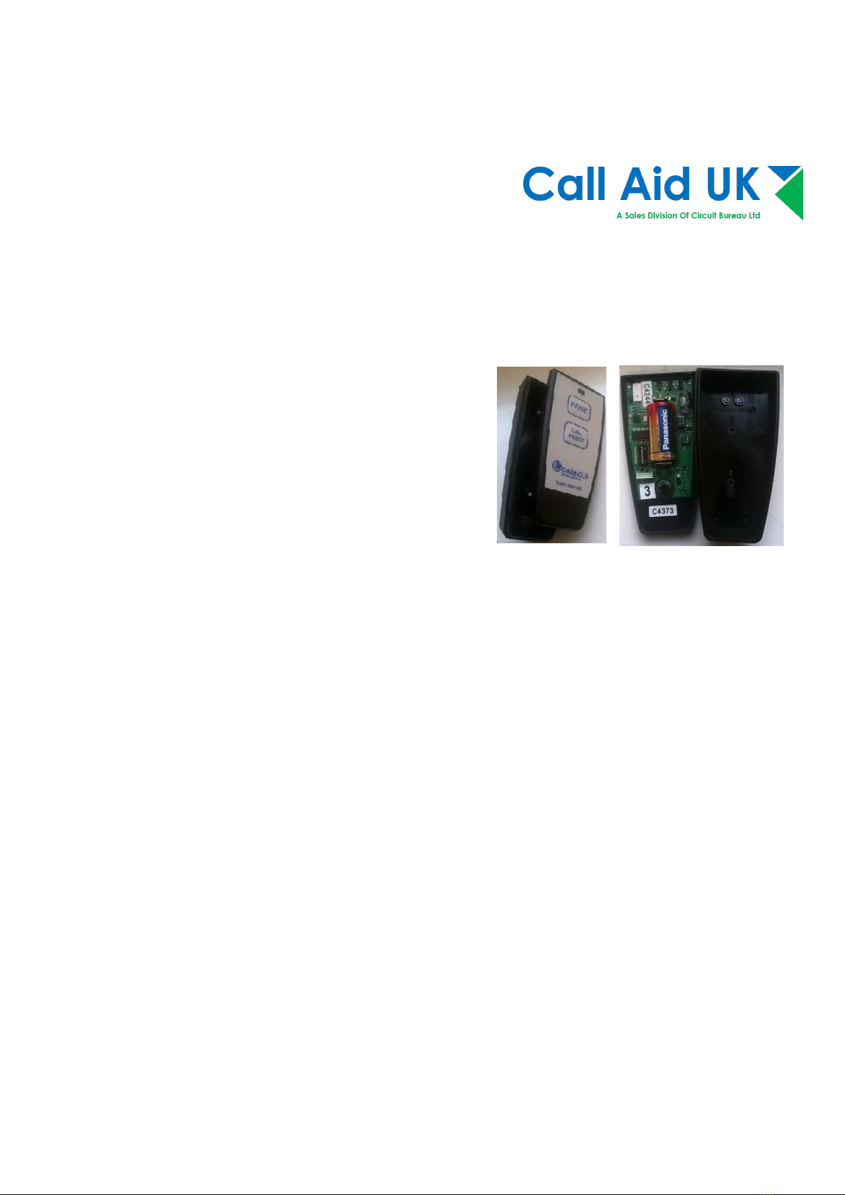
The battery type is: CR2032
Changing the battery
The CR2032 button cell will power this call button for many months (depending on usage). To
change the battery, remove the screw on the rear of the housing. Pull the rubber holder away
from the housing to allow purchase on the edge of the housing to separate the two halves.
The battery can be lifted out of its holder. Replace with a new battery.
To reassemble, ensure that the rubber strap holder is correctly fitted to the back half of the
housing before placing the other half in position. A gentle squeeze should bring the two halves
together. Refit the screw (Do not over tighten as damage may result), refit the strap or lanyard.
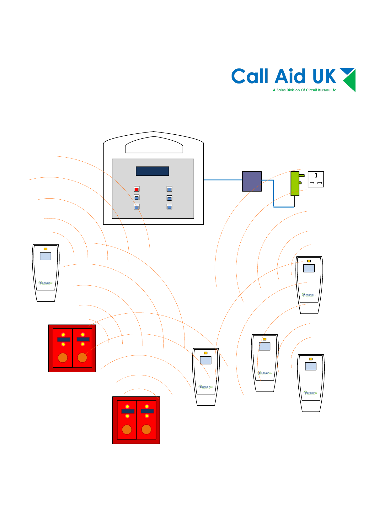
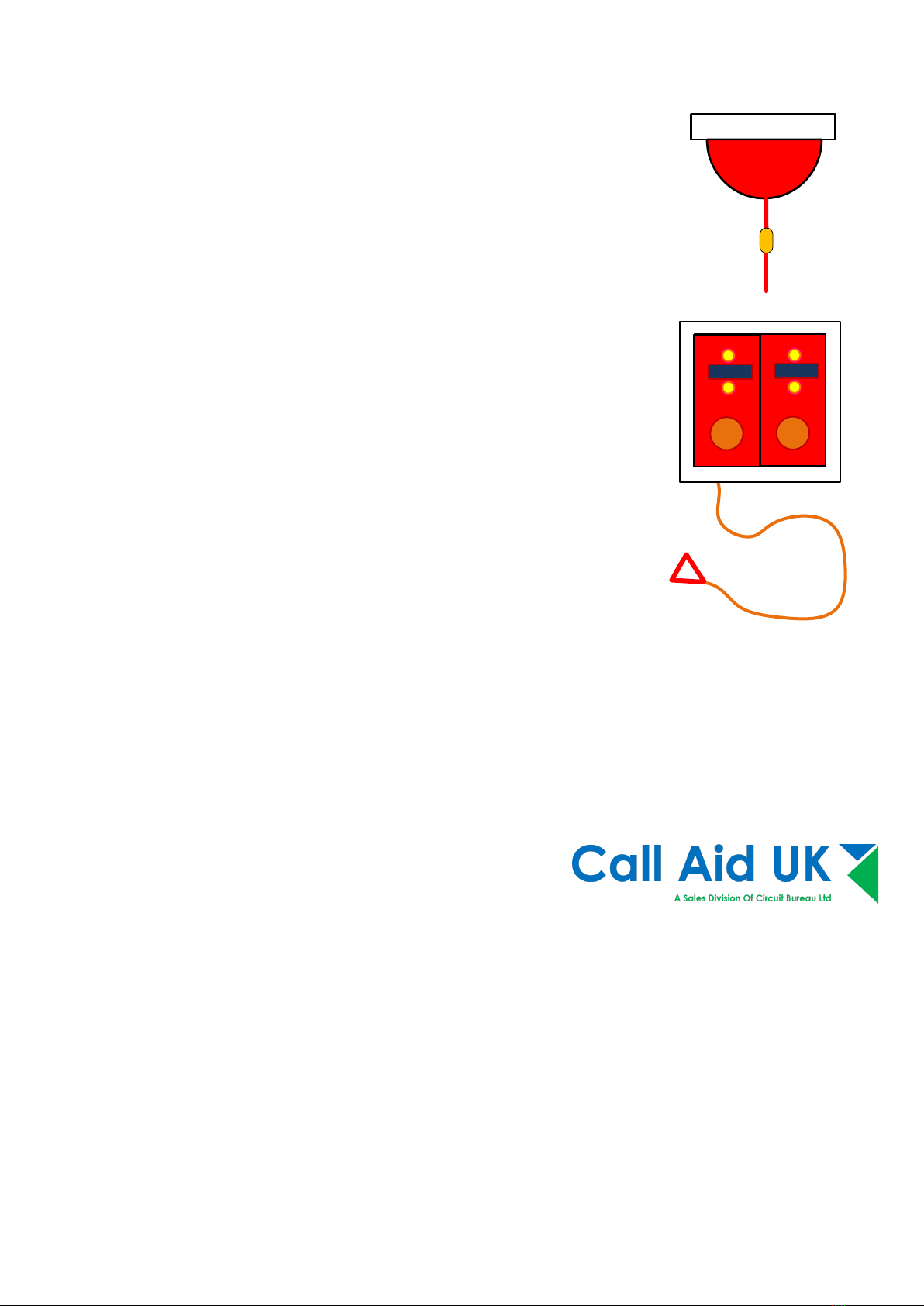
Wall mounted Call alert button
These wall units have two buttons. Pressing the GREEN button will send an
assist call signal to the 1142 master which will display the identity of the call
alert button and a low level audio alert. Pressing the RED button on the
wall unit will send a high level alert to the 1142 master.
The labels in the buttons will vary depending on the application or usage.
Cancelling at source
To cancel an alert at the call unit press and hold both buttons. The reassurance lights will stop
flashing and the alert will have cleared from the 1142 master panel.
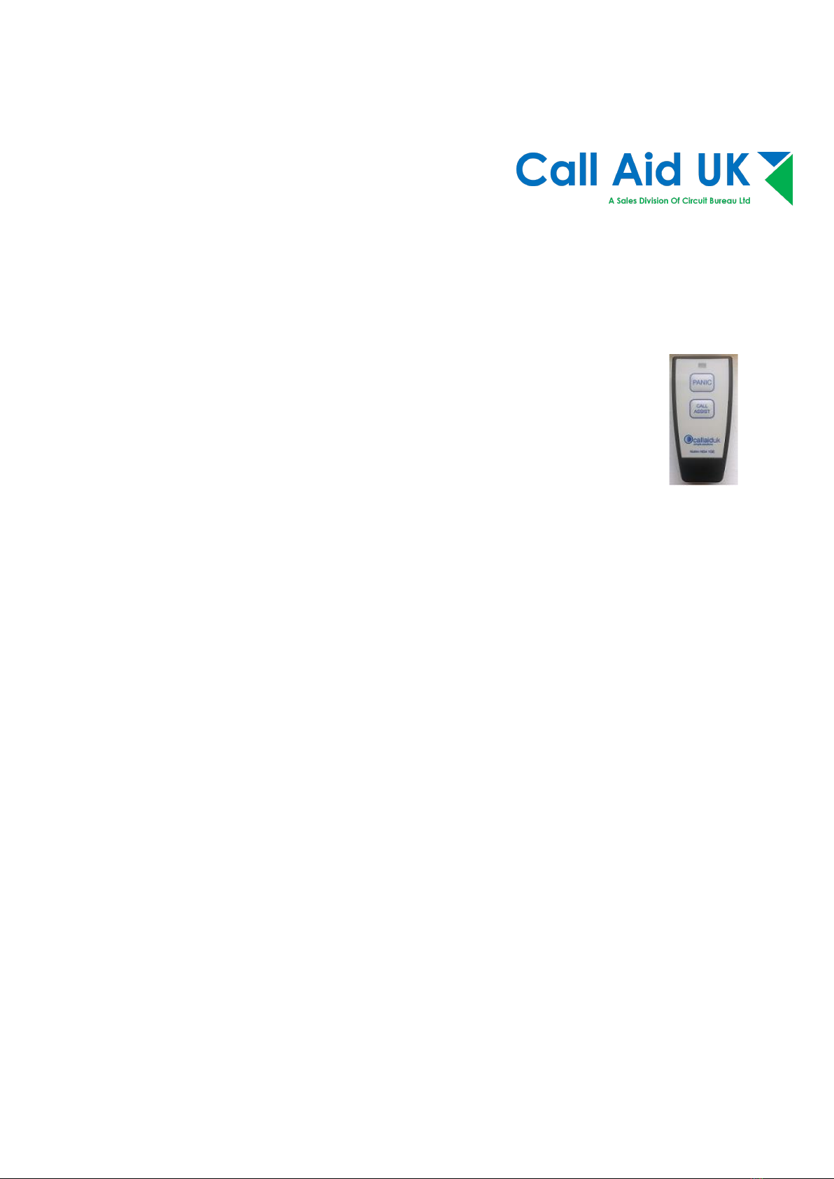
Call & Panic Buttons for this System…continued
Radio Under desk Call alert button
The under desk Call alert button has two red buttons; these buttons have
a large dimple to assist the operator to find the correct part of the button
to press. When either buttons is pressed a Call alert is sent to the 1142RX
master. There is a red lamp mounted on the side facing out as a
reassurance lamp to be seen by the operator. When installing this unit
ensure that the dimples are nearest to the operator.
Cancelling at source
To cancel an alert at the call unit press and hold both buttons. The reassurance lights will stop
flashing and the alert will have cleared from the 1142RX master panel.