THIS SYMBOL MEANS: ATTENTION!
BECOME ALERT! YOUR SAFETY IS INVOLVED!
Note the use of the signal words DANGER, WARNING and CAUTION with the safety messages. The
appropriate signal word for each has been selected using the following guidelines:
DANGER: Indicates an imminently hazardous situation that, if not avoided, will result in
death or serious injury. This signal word is to be limited to the most extreme situations
typically for machine components which, for functional purposes, cannot be guarded.
WARNING: Indicates a potentially hazardous situation that, if not avoided, could result
in death or serious injury, and includes hazards that are exposed when guards are removed.
CAUTION: Indicates a potentially hazardous situation that, if not avoided, may result in
minor or moderate injury.
NOTICE is used to address safety practices not related to personal safety.
This equipment is dangerous to children and persons unfamiliar with its operation. The operator
should be a responsible adult familiar with farm machinery and trained in this equipment’s
operations. Do not allow persons to operate or assemble this unit until they have
read this manual and have developed a thorough understanding of the safety
precautions of how it works.
SAFETY SIGNS
Sharp Objects signs are placed on the exterior of all stalk roll boxes. See
the sign, right, for reference and understand the associated cutting dangers
with the enclosed product.
BEFORE OPERATION
• Carefully study and understand this manual.
• Do not wear loose-fitting clothing which may catch on moving parts.
• Always wear protective clothing and substantial shoes.
• Always wear provided cut-resistant gloves when installing stalk rolls
3 www.CalmerCornHeads.com
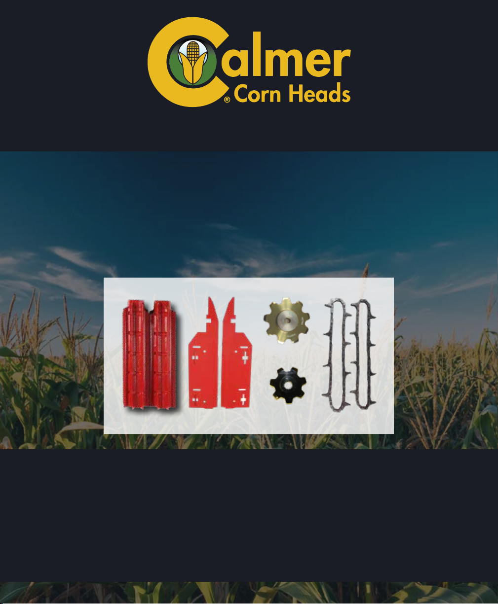
(2) STALK ROLL
COUPLERS