Aperture D
Aperture E
415mm
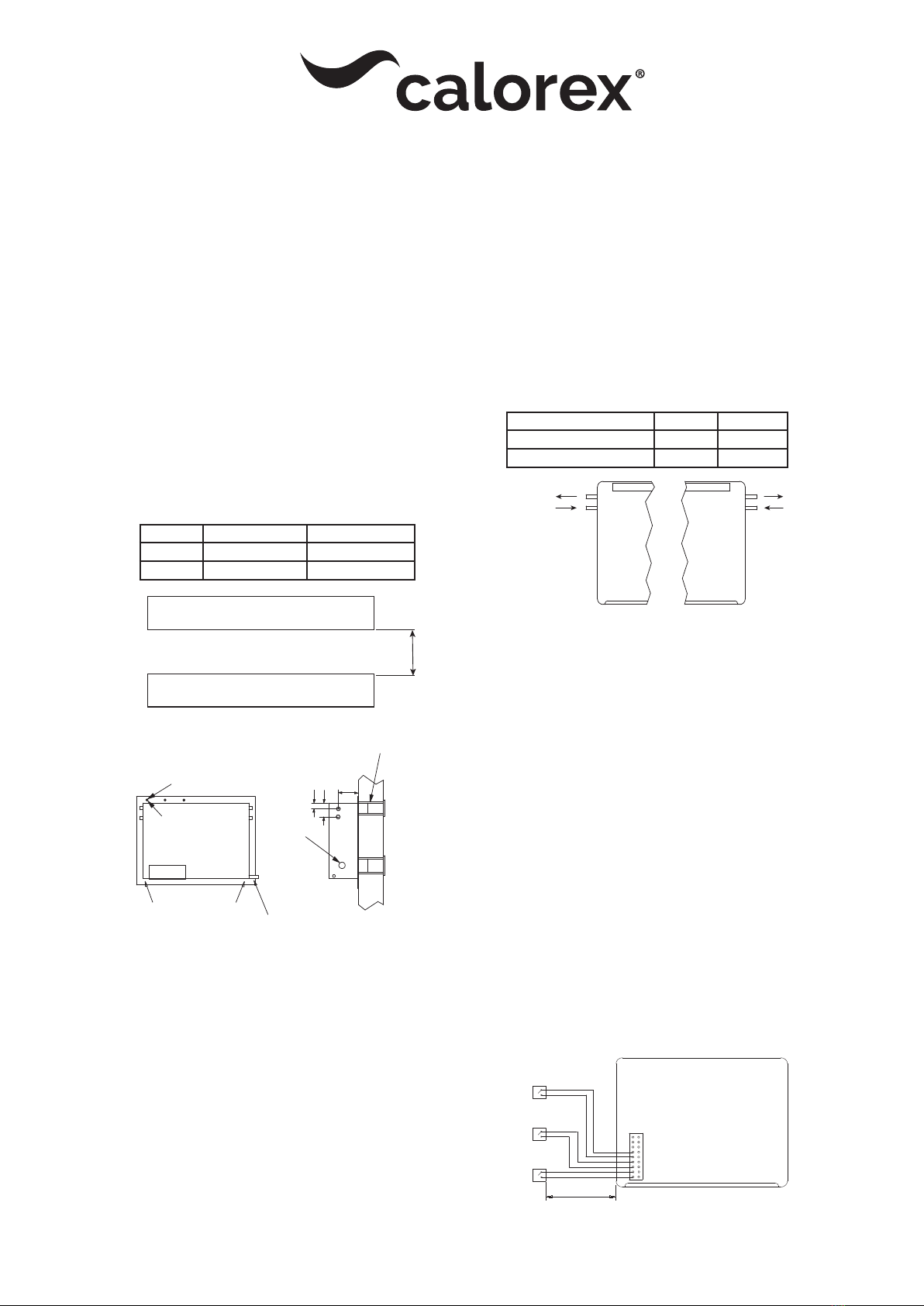
100M MAX
1mm SQ CABLE
Remote Air Stat
(Not supplied)
Remote Humidistat
(Not supplied)
Remote On/Off
Switch (Not supplied)
REMOTE THERMOSTAT
REMOTE HUMIDISTAT
REMOTE ON/OFF
FIG 2 WIRING DIAGRAM
‘D’ Aperture ‘E’ Aperture
TTW30/33 85 high X 520 long 110 high X 520 long
TTW55/60 85 high X 980 long 110 high X 520 long
PLANT ROOM VIEW OF MACHINE
Humidistat control knob &
mains terminal block TTW33
(Opposite side on TTW55).
Fit cavity bridging pieces & grilles
supplied & ensure all joints are sealed
wi silicon caulking.
Condensate drain tube
10mm bore
TTW33
Mains in
TTW55
Spot rough wall plate fixing
holes (12 off) and drill
6mm x 60mm deep holes in wall.
Fix wall plate wi 2” x No 10
screws supplied.
‘C’ holes 218mm
143mm
108mm
Mains in
TTW33 TTW55
Water flow as shown
in table.
15mm stubs
PLANT VIEW OF MACHINE
Water flow as shown
in table.
15mm stubs
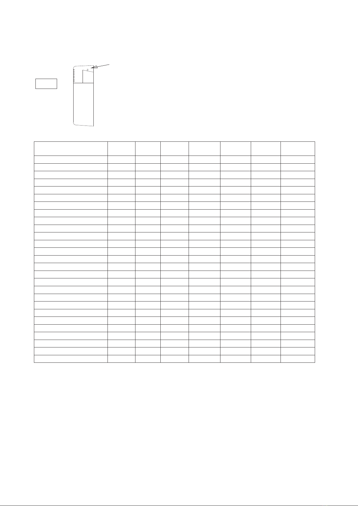
TTW30/33 TTW55/60
Unit flow rate L/min 5.0 5.0
Unit pressure drop m head 1.1 1.8
HEALTH & SAFETY WARNING
As e Heat Pump contains electrical and rotational equipment, it is recommended at ONLY competent persons carry out any work on is type of machine
(see guarantee). Isolate electrically before entering machine or removing panels.
This appliance is not intended for use by persons (including children) wi reduced physical,sensory or mental capabilities, or lack of
experience and knowledge, unless ey have been given supervision or instruction concerning use of e appliance by a person responsible
for eir safety. Children should be supervised to ensure at ey do not play wi e appliance.
The Calorex TTW units are designed for installation in a heated room, adjacent to e poolroom.
INSTALLATION MODELS TTW30/33/55/60.
1. Remove machine from packaging.
2. Check bo sides of wall, mark out apertures ‘D’ and ‘E’ in required location
and ensure ey are level.
3. Cut out apertures ‘D’ and ‘E’ wi due consideration to structure and safety
using a suitable lintel to bridge e gap.
4. Remove e four bolts holding e dehumidifier to e wall plate and also
e ear lead.
5. Locate e wall plate in apertures and ensure it is level. Drill and fix using
12 ‘C’ holes and wall plugs /screws provided. Hole size 6mm (No 10) x
60mm.
6. Li e dehumidifier on to wall and replace six M6 bolts ald wall plate ear
lead.
7. Fix supplied cavity bridging pieces and air inlet/outlet grilles, ensure all joints
are sealed wi silicon caulking.
8. Electrical supply to e unit must be sized according to data on serial
number label paying special attention to I.E.E. regulations latest edition
regarding e special conditions governing electrical supply to machines in
potentially damp areas. The machine should be installed in accordance wi
EMC2004/108/EC.
9. The electrical supply should be connected to e terminal block mounted
on e side of e bracket supporting e compressor. Brown/red to 'live',
blue/black to neutral and ear to e stud provided.
10. Fan mode switch can be set to cycle fan when humidistat senses demand
but should be set to continuous to promote good air circulation and reduce
condensation. Note at on models fitted wi LPHW e fan(s) will start
automatically whenever ere is an air heating demand. On 'X' models
fan(s) will stop during defrost cycle.
11. Locate pipe from drip tray and run away to waste, a short leng of 10mm
pipe is provided which should be led into a fixed waste pipe (ensure an air
gap, tun dish).
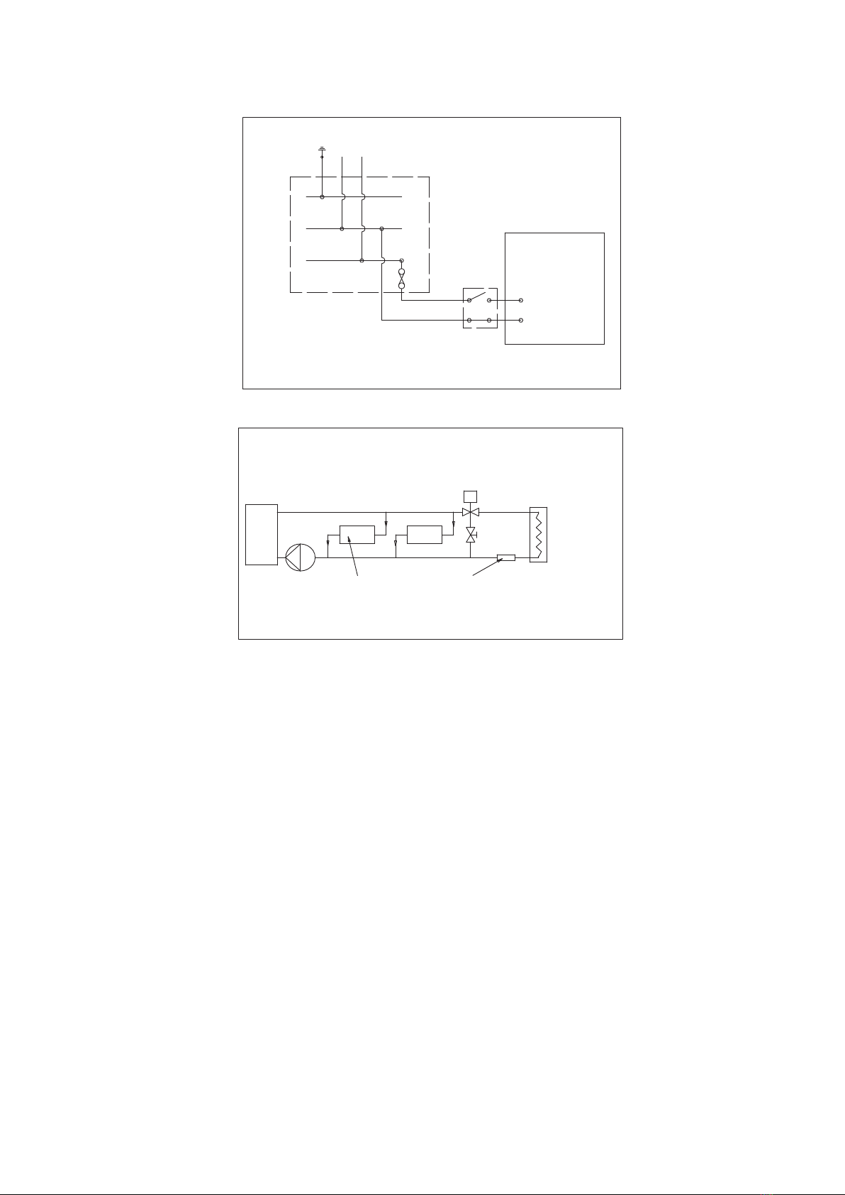
MODELS WITH L.P.H.W FITTED
12. Connect water circuit piping to 15mm stubs projecting from side of
machine as per diagram below:
13. It is recommended at isolating valves are fitted to enable isolation of e
machine in e event of service.
Complete water circuit as per diagrams overleaf.
(a) Circulating pump must be sized to take into account e design flow
rate of e machine plus e water system resistance. For Pressure drops
see data section.
12V REMOTE HUMIDISTAT, THERMOSTAT, & REMOTE ON/OFF
CONNECTIONS
(These options need to be specified when ordering e
dehumidifier)
REMOTE HUMIDISTAT
14. Remove link wire from mains in terminal block marked ‘Remote Humidistat
and connect remote humidistat as shown below, ensure dial on internal
humidistat is set fully anti-clockwise (ie maximum dehumidifcation).
REMOTE ON/OFF
15. Remove e link from e mains in terminal block marked Remote On/Off.
and connect to a switch as shown below.
'P' MODELS WITH RESISTANCE HEATER
16. Connect remote air ermostat as shown above to mains in terminal block
marked Remote Thermostat
17. Ensure safety ermostat(s) below are set, ie push red button(s).
18. Replace front cover, turn on electrical supply and turn humidistat towards
20%. (Unless remote humidistat fitted, see note 14 above) unit fan will
start, followed 6 minutes later by e compressor.
19. It is recommended at e fan mode switch is set to continuous, as in
cycle mode e fan and heaters only run togeer if ere is a demand for
dehumidification.
SD373351 ISSUE 12