Calpeda SPA User manual

Pompe autodrenanti per idromassaggio
Self-draining whirlpool pumps
Selbstentleerende Whirlpoolpumpen
Ä‚ÚÓχÚ˘ÂÒÍË „ˉÓχÒÒ‡ÊÌ˚ ̇ÒÓÒ˚ ÒÂËË
SPA
ISTRUZIONI ORIGINALI PER L’USO Pagina 2 Italiano
OPERATING INSTRUCTIONS Page 8 English
BETRIEBSANLEITUNG Seite 14 Deutsch
IàÌÒÚÛ͈ËË ÔÓ ˝ÍÒÔÎÛ‡Ú‡ˆËË ëÚ. 20 êÛÒÒÍËÈ
SPA Rev7.indd 1 08/02/19 17:46

IT
Pagina 2 / 28 SPA Rev7 - Istruzioni originali
ILPRESENTE MANUALE ISTRUZIONI È PROPRIETÀ
DI CALPEDA S.p.A. OGNI RIPRODUZIONE, ANCHE
PARZIALE, È VIETATA.
1. INFORMAZIONI GENERALI
Prima di utilizzare il prodotto leggere attentamente
le avvertenze e le istruzioni riportate in questo
manuale, che deve essere conservato per una futura
consultazione.
La lingua originale di redazione è l’italiano, che farà
fede in caso di difformità nelle traduzioni.
Il manuale è parte integrante dell’apparecchio come
residuo essenziale di sicurezza e deve essere
conservato no allo smantellamento nale del prodotto.
L’acquirente può richiedere copia del manuale in
caso di smarrimento contattando Calpeda S.p.A. e
specicando il tipo di prodotto riportato sull’etichetta
della macchina (Rif. 2.3 Marcatura).
In caso di modiche, manomissioni o alterazioni
dell’apparecchio o parti di esso non autorizzate dal
fabbricante, la “dichiarazione CE” perde di validità e
con essa anche la garanzia.
L'apparecchio può essere utilizzato
da bambini di età non inferiore a
8 anni e da persone con ridotte
capacità siche, sensoriali o mentali,
o prive di esperienza o della
necessaria conoscenza, purchè
sotto sorveglianza oppure dopo che
le stesse abbiano ricevuto istruzioni
relative all'uso sicuro dell'apparecchio
e alla comprensione dei pericoli ad
esso inerenti. I bambini non devono
giocare con l'apparecchio. La pulizia e
la manutenzione destinata ad essere
effettuata dall'utilizzatore non deve
essere effettuata da bambini senza
sorveglianza.
Leggere attentamente la sezione
installazione dove è riportata:
-
la massima prevalenza strutturale
ammessa nel corpo pompa (capitolo 3.1).
- il tipo e la sezione del cavo di
alimentazione (capitolo 6.5).
-
il tipo di protezione elettrica da
installare (capitolo 6.5).
1.1. Simbologia utilizzata
Per migliorare la comprensione si utilizzano i simboli/
pittogrammi sotto riportati con i relativi signicati.
Informazioni ed avvertenze che devono
essere rispettate, altrimenti sono causa
di danneggiamenti all’apparecchio o
compromettono la sicurezza del personale.
Informazioni ed avvertenze di carattere elettrico
il cui mancato rispetto può danneggiare
l’apparecchio o compromettere la sicurezza
del personale.
i
Indicazioni di note e avvertimenti per la
corretta gestione dell’apparecchio e dei suoi
componenti.
Interventi che possono essere svolti
dall’utilizzatore nale dell’apparecchio. Previa
lettura delle istruzioni, e il responsabile per
il suo mantenimento in condizioni di utilizzo
normali. È autorizzato a fare operazioni di
manutenzione ordinaria.
Interventi che devono essere svolti da un
elettricista qualicato abilitato a tutti gli
interventi di natura elettrica di manutenzione
e di riparazione, e in grado di operare in
presenza di tensione elettrica.
Interventi che devono essere svolti da un
tecnico qualicato in grado di utilizzare
correttamente l’apparecchio in condizioni
normali, abilitato a tutti gli interventi di natura
meccanica di manutenzione, di regolazione e
di riparazione.
Indica l’obbligo di uso di dispositivi di protezione
individuale - protezione delle mani.
OFF
Interventi che devono essere svolti con
l’apparecchio spento e scollegato dalle fonti di
energia.
ON
Interventi che devono essere svolti con
l’apparecchio acceso.
1.2. Ragione sociale e indirizzo del Fabbricante
Ragione sociale: Calpeda S.p.A.
Indirizzo: Via Roggia di Mezzo, 39
36050 Montorso Vicentino - Vicenza / Italia
www.calpeda.it
1.3. Operatori autorizzati
Il prodotto è rivolto a operatori esperti divisi tra
utilizzatori nali del prodotto e tecnici specializzati
(vedi simboli sopra).
i
E’ vietato per l’utilizzatore nale eseguire
operazioni riservate ai tecnici specializzati. Il
fabbricante non risponde di danni derivati dalla
mancata osservanza di questo divieto.
1.4. Garanzia
Per la garanzia sui prodotti fare riferimento alle
condizioni generali di vendita.
i
La garanzia include sostituzione o riparazione
GRATUITA delle parti difettose (riconosciute
dal fabbricante).
INDICE
1. INFORMAZIONI GENERALI .......................... 2
2. DESCRIZIONE TECNICA............................... 3
3. CARATTERISTICHE TECNICHE ...................3
4. SICUREZZA....................................................3
5. TRASPORTO E MOVIMENTAZIONE.............4
6. INSTALLAZIONE ............................................4
7. AVVIO E IMPIEGO .........................................5
8. MANUTENZIONE ...........................................5
9. SMALTIMENTO ..............................................6
10. RICAMBI......................................................... 6
11. DENOMINAZIONE DELLE PARTI.................. 6
12. RICERCA GUASTI..........................................7
Disegno per lo smontaggio ed il rimontaggio ........26
Dichiarazione di conformità ...................................28
SPA Rev7.indd 2 08/02/19 17:46

IT
SPA Rev7 - Istruzioni originali Pagina 3 / 28
La garanzia dell’apparecchio decade:
- Qualora l’uso dello stesso non sia conforme alle
istruzioni e norme descritte nel presente manuale.
- Nel caso di modiche o variazioni apportate
arbitrariamente senza autorizzazione del Fabbricante
(vedi par. 1.5).
- Nel caso di interventi di assistenza tecnica eseguiti
da personale non autorizzato dal Fabbricante.
- Nel caso di mancata manutenzione prevista nel
presente manuale.
1.5. Servizio di supporto tecnico
Qualsiasi ulteriore informazione sulla documentazione,
sui servizi di assistenza e sulle parti dell’apparecchio,
può essere richiesta a Calpeda S.p.A. (vedi paragrafo
1.2)
2. DESCRIZIONE TECNICA
Pompe monogiranti, autodrenanti, con motore isolato
dall’acqua, costruite con materiali plastici di altissima
qualità resistenti alla corrosione, con diffusore in
acciaio inossidabile.
Collegamento tubi in PVC:
Bocche per collegamento ad incollaggio, con lettatura
esterna per bocchettone di raccordo.
2.1. Uso previsto
Per la circolazione dell'acqua in vasche e minipiscine
per idromassaggio.
Per acqua pulita con la temperatura massima di 60 °C.
Limitare la temperatura massima dell'acqua
all'ingresso nella vasca da idromassaggio a 50
°C.
Massimo livello di acqua consentito nella vasca: 2.000
mm sopra la pompa.
2.2. Uso scorretto ragionevolmente prevedibile
L’apparecchio è stato progettato e costruito
esclusivamente per l’uso descritto nel par. 2.1.
È assolutamente vietato l’impiego
dell’apparecchio per usi impropri, e modalità di
uso non previste dal presente manuale.
L’utilizzo improprio del prodotto deteriora le
caratteristiche di sicurezza e di efcienza
dell’apparecchio, Calpeda non può essere
ritenuta responsabile per guasti o infortuni dovuti
all’inosservanza dei divieti sopracitati.
Non usare l’apparecchio in stagni, vasche e
piscine quando nell’acqua si trovano persone.
2.3. Marcatura
Di seguito una copia della targhetta di identicazione
presente sull’involucro esterno della pompa.
1 Tipo
2 Portata
3 Prevalenza
4 Potenza nominale
5 Tensione di alim.
6 Corrente
7 Eventuali note
8 Frequenza
9 Tipo di servizio
10 Classe isol.
11 Peso
12 cosø
13 Velocità nominale
14 Protezione
15 Matricola
16 Certicazioni
Esempio targhetta pompa
XXXXXXX
Q min/max X/X m3/h
XXXXXXX
H max/min X/X mIP XX
n XXXX/min
220∆/380Y V3~50Hz cosø X
X/X A
XXXXXXXX
S1 l.cl. XXkg
XkW (XHp) S.F.
1
2
3
4
5
6
7
8910
16
15
14
13
12
11
Montorso (VI) Italy IT 00142630243
Made in Italy
3. CARATTERISTICHE TECNICHE
3.1. Dati tecnici
Dimensioni di ingombro e pesi (vedi catalogo).
Velocità nominale 2900/3450 rpm
Protezione IP X5
Tensione di alimentazione/ Frequenza:
- no a 240V 1~ 50/60 Hz
- no a 480V 3~ 50/60 Hz
Vericare che la frequenza e la tensione di rete sia idonea
alle caratteristiche elettriche indicate in targhetta.
I dati elettrici riportati in targhetta si riferiscono alla
potenza nominale del motore.
Pressione sonora: < 70 dB (A).
Avviamenti/ora max.: n. 30 ad intervalli regolari .
Pressione nale massima ammessa nel corpo pompa:
25 m (2,5 bar).
Pressione massima in aspirazione: PN (Pa) - Hmax (Pa).
3.2. Ambiente in cui viene posizionata la pompa
Elettropompe previste per luoghi aerati e protetti dalle
intemperie con temperatura massima ambiente di
40°C.
4. SICUREZZA
4.1. Norme comportamentali generiche
Prima di utilizzare il prodotto è necessario
conoscere tutte le indicazioni riguardanti la
sicurezza.
Si deve leggere attentamente e seguire tutte le
istruzioni tecniche, di funzionamento e le indicazioni
qui contenute per i differenti passaggi: dal trasporto
allo smaltimento nale.
I tecnici specializzati sono tenuti al rispetto dei
regolamenti, regolamentazioni, norme e leggi del
paese in cui la pompa è venduta.
L’apparecchio è conforme alle vigenti norme di sicurezza.
L’uso improprio può comunque provocare danni a
persone, cose o animali.
Il fabbricante declina ogni responsabilità in caso di tali
danni o da uso in condizioni diverse da quelle indicate
in targa e nelle presenti istruzioni.
i
Rispettare la cadenza degli interventi di
manutenzione e la tempestiva sostituzione
dei pezzi danneggiati o usurati, permette
all’apparecchio di lavorare sempre nelle migliori
condizioni. Usare solo ed esclusivamente
pezzi di ricambio originali forniti da CALPEDA
S.p.A.o da un distributore autorizzato.
Non rimuovere o alterare le targhe apposte dal
fabbricante sull’apparecchio.
L’apparecchio non deve essere messo in funzione in
caso di difetti o parti danneggiate.
Le operazioni di manutenzione ordinaria e
straordinaria, che prevedono uno smontaggio
anche parziale dell’apparecchio, devono
essere effettuate solo dopo aver interrotto
l’alimentazione dell’apparecchio stesso.
4.2. Dispositivi di sicurezza
L’apparecchio è costituito da una scocca esterna che
impedisce contatti con gli organi interni e gli elementi
in tensione.
4.3. Rischi residui
L’apparecchio, per progettazione e destinazione d’uso
(rispetto uso previsto e norme di sicurezza), non
presenta rischi residui.
4.4. Segnaletica di sicurezza e informazione
Per questo tipo di prodotto non è prevista segnaletica
sul prodotto.
SPA Rev7.indd 3 08/02/19 17:46

IT
Pagina 4 / 28 SPA Rev7 - Istruzioni originali
4.5. Dispositivi di protezione individuale (DPI)
Nelle fasi di installazione avviamento e manutenzione si
consiglia agli operatori autorizzati di valutare, quali siano
i dispositivi idonei al lavori descritti.
Nelle operazioni di manutenzione ordinaria e
straordinaria, è previsto l’uso dei guanti per la protezione
delle mani.
Segnale DPI obbligatori
PROTEZIONE DELLE MANI
(guanti per la protezione da rischio chimico,
termico e meccanico)
5. TRASPORTO E MOVIMENTAZIONE
Il prodotto è imballato per mantenere integro il
contenuto.
Durante il trasporto evitare di sovrapporre pesi
eccessivi. Assicurarsi che durante il trasporto la
scatola non sia libera di muoversi.
Non sono necessari particolari mezzi per trasportare
l’apparecchio imballato.
I mezzi per trasportare l’apparecchio imballato, devono
essere adeguati alle dimensioni e ai pesi del prodotto
scelto (vedi dimensioni di ingombro a catalogo).
5.1. Movimentazione
Movimentare con cura l’imballo, che non deve subire
urti.
Si deve evitare di sovrapporre agli imballi altro
materiale che potrebbe deteriorare la pompa.
6. INSTALLAZIONE
6.1. Dimensioni di ingombro
Per le dimensioni di ingombro dell’apparecchio (vedi
catalogo).
6.2. Requisiti ambientali e dimensioni del luogo
di installazione
Il cliente deve predisporre il luogo di installazione in
modo adeguato alla corretta installazione e in coerenza
alle esigenze costruttive della stessa (allacciamenti
elettrico, ecc...).
L’ambiente in cui installare l’apparecchio deve avere i
requisiti del paragrafo 3.2.
È assolutamente vietata l’installazione e la messa in
servizio della macchina in ambienti con atmosfera
potenzialmente esplosiva.
6.3. Disimballaggio
i
Vericare che l’apparecchio non sia stato
danneggiato durante il trasporto.
Il materiale d’imballo, una volta disimballata la
macchina, dovrà essere eliminato e/o riutilizzato
secondo le norme vigenti nel Paese di destinazione
dell’apparecchio.
6.4. Installazione
Le pompe Compact SPA sono previste per
l’installazione con l’asse del rotore orizzontale e piedi di
appoggio in basso, in impianti in cui il riempimento e lo
svuotamento della pompa avviene attraverso i tubi,
con il riempimento e lo svuotamento della vasca.
Le vasche per idromassaggio devono essere
costruite in modo tale che l’acqua non possa restare
nel sistema dopo che la vasca è stata vuotata.
Per consentire l’autodrenaggio (lo svuotamento),
montare la pompa su una base disposta su un livello pari
o superiore alla bocchetta di aspirazione sulla vasca e,
per consentire il riempimento, con la bocca di mandata
disposta su un livello inferiore a quello del normale
riempimento (sotto lo scarico con troppo pieno).
L’installazione sotto il bordo della vasca chiusa
esternamente con pannelli di protezione deve
prevedere almeno una fessura con 5-10 mm di apertura
(preferibilmente tra pannello e pavimento), adatta al
ricircolo d’aria per la ventilazione del motore.
Montare la pompa su una base situata almeno 40
mm sopra la supercie d’installazione. Per vasche
o minipiscine installate all’esterno prevedere la
protezione della pompa e delle parti elettriche dal
sole, dalle intemperie e da allagamenti ed installare la
pompa su una base situata almeno 100 mm sopra la
supercie d’installazione.
Prevedere che l’installazione consenta l’accesso per
ispezioni, lo smontaggio o l’eventuale sostituzione
della pompa.
Applicare le prescrizioni delle norme di sicurezza
(alcune norme di riferimento sono indicate nel capitolo 6.5).
6.4.1. Tubazioni
Collegamento dei tubi alle bocche della pompa.
Impiegare tubi di materiale plastico, tipo PVC.
Le bocche della pompa sono previste per il
collegamento diretto ad incollaggio (g. 1).
La lettatura esterna consente il collegamento con
bocchettone di raccordo opzionale smontabile (g. 2).
3.93.033/1
3.93.033/2
Fig. 1 Connessione ad incollaggio.
3.93.033/1
3.93.033/2
Fig. 2 Connessione con bocchettone lettato.
Per l’incollaggio del tubo alla pompa o al bocchettone
usare un collante adatto al materiale ABS. Seguire
attentamente le istruzioni del prodotto da usare.
Serrare i bocchettoni solo quanto basta per
assicurare la tenuta.
Un serraggio eccessivo può danneggiare la pompa
o i bocchettoni stessi. Vericare che tutte le giunzioni
siano a perfetta tenuta.
Il diametro delle tubazioni non deve essere inferiore al
diametro delle bocche della pompa.
Montare nella bocca di aspirazione della vasca un ltro
estraibile.
Il tubo aspirante deve avere una lunghezza minima
di 500 mm e deve avere un andamento ascendente
dalla bocca di aspirazione sulla vasca no alla bocca
aspirante della pompa. Anche il tubo di mandata deve
essere disposto in modo da svuotarsi completamente
con lo svuotamento della vasca.
6.5. Collegamento elettrico
OFF
Il collegamento elettrico deve essere eseguito
da un elettricista qualicato nel rispetto delle
prescrizioni locali.
Seguire le norme di sicurezza EN 60335-2-41, EN
60335-2-60 ed adottare tutte le misure di protezione
delle norme di installazione.
SPA Rev7.indd 4 08/02/19 17:46

IT
SPA Rev7 - Istruzioni originali Pagina 5 / 28
Eseguire il collegamento a terra. Collegare il
conduttore di protezione al morsetto contrassegnato
con il simbolo .
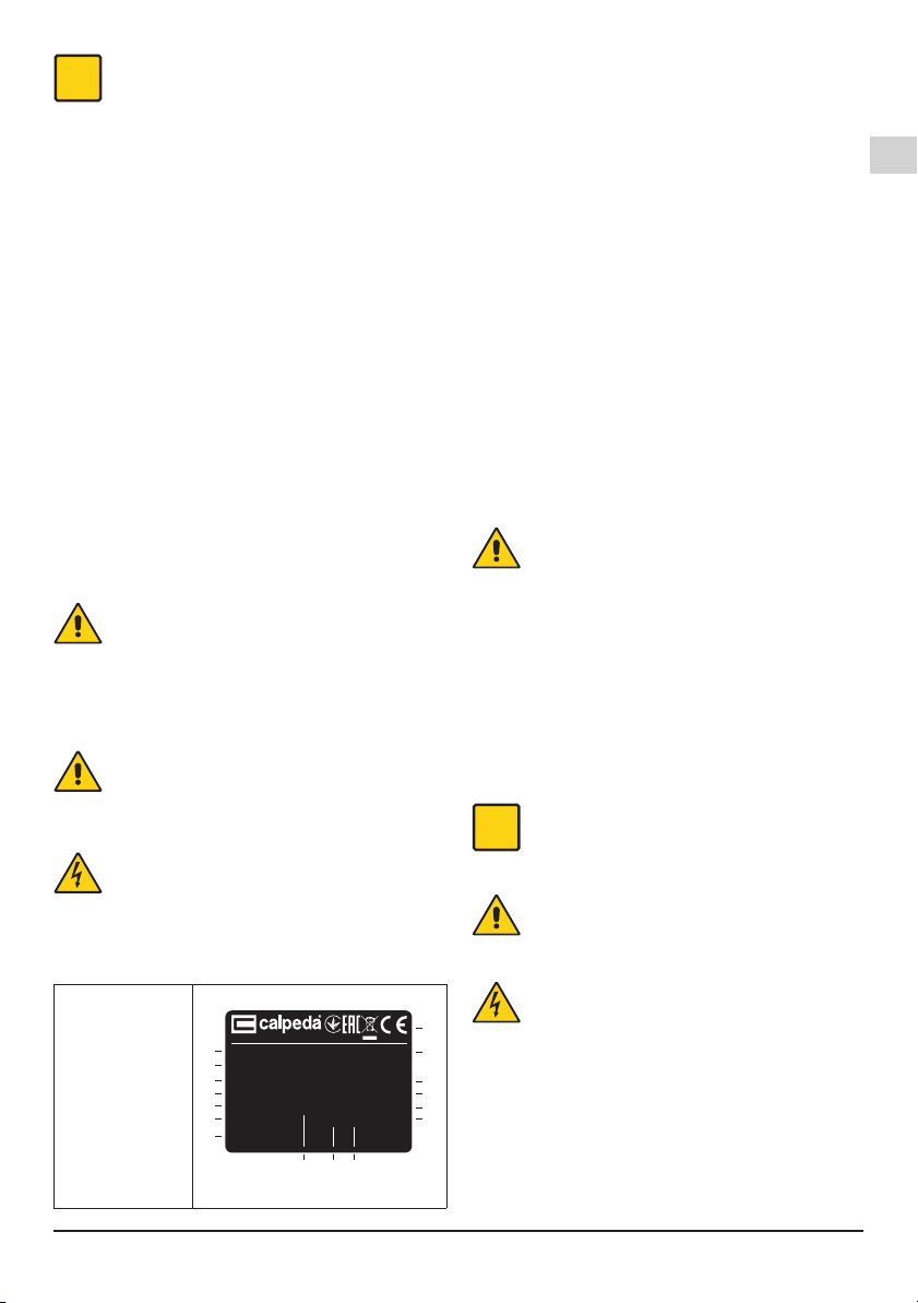
Confrontare la frequenza e la tensione di rete con i
dati di targa e collegare i conduttori di alimentazione
ai morsetti secondo il corrispondente schema riportato
all’interno del coperchio della scatola morsetti.
ATTENZIONE: non fare mai cadere una
rondella o altre parti metalliche nel
passaggio cavi interno tra scatola morsetti
e statore. Se accade, smontare il motore e
recuperare la parte caduta.
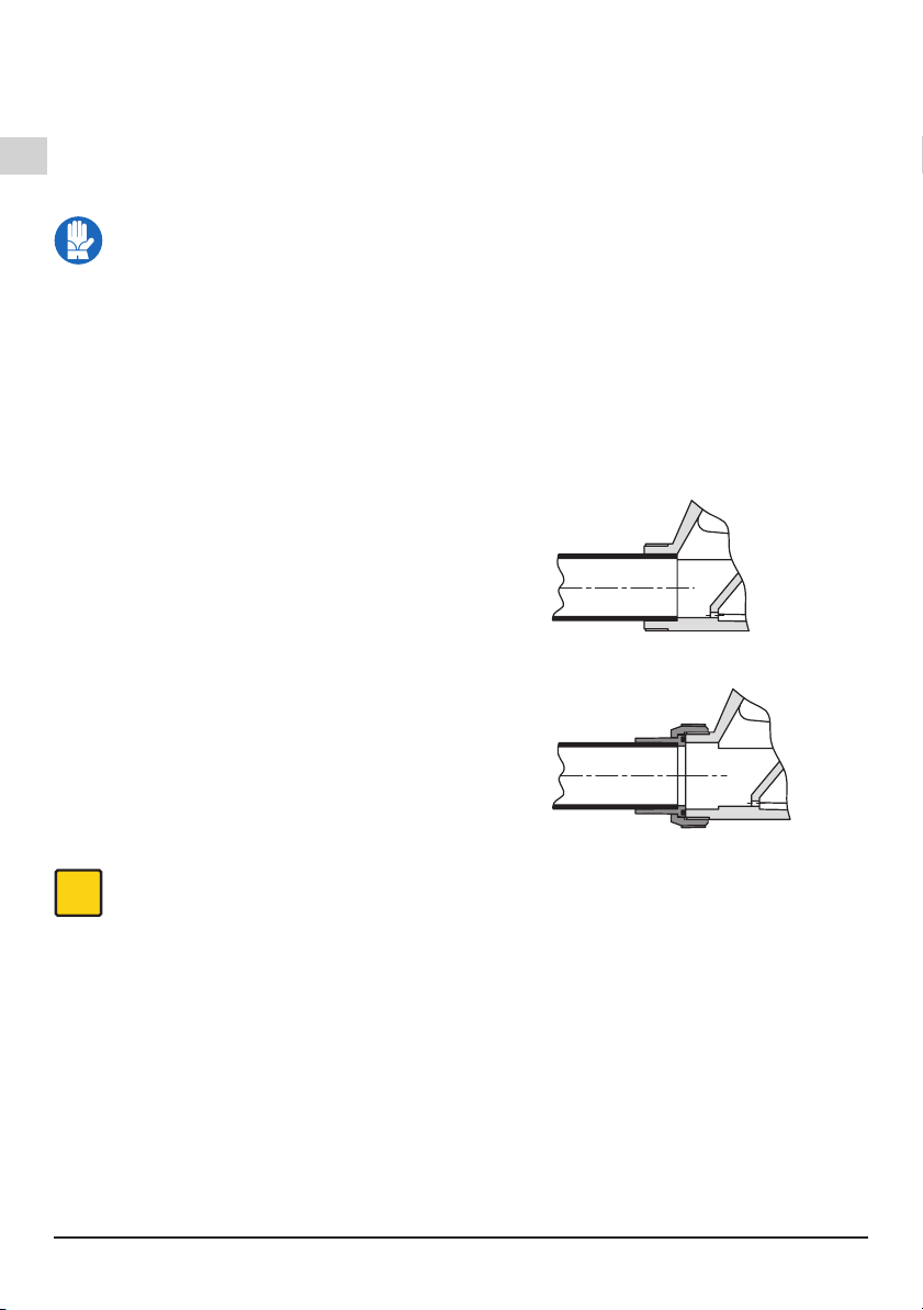
Il cavo di alimentazione essibile deve essere
almeno del tipo H05 RN-F oppure H05 VV-F. Per le
vasche o minipiscine installate all’esterno il cavo di
alimentazione deve essere almeno del tipo H07 RN-F
con sezione del cavo pari o superiore (cap. 12.5 TAB 1)
..
Tutti i componenti elettrici devono essere collocati
fuori della portata di mano delle persone che usano la
vasca e devono essere collocati o ssati in modo tale
che non possano cadere nella vasca.
Eseguire i collegamenti equipotenziali.
Collegare ad un circuito protetto da interruttore
differenziale con I∆N ≤ 30 mA.
Installare un dispositivo per la onnipolare
disinserzione dalla rete (interruttore per scollegare
la pompa dall’alimentazione) con una distanza di
apertura dei contatti di almeno 3 mm.
Con alimentazione trifase installare un adeguato
salvamotore con curva D come da corrente di targa.
Le elettropompe monofasi SPAM, sono fornite con
condensatore collegato ai morsetti e (per 220-240 V -
50 Hz) con termoprotettore inserito.
7. AVVIO E IMPIEGO
7.1. Controlli prima dell’accensione
L’apparecchio non deve essere messo infunzione in
presenza di parti danneggiate.
7.2. Primo avviamento
OFF
ATTENZIONE: evitare assolutamente il
funzionamento a secco, neanche per prova.
Avviare la pompa dopo il riempimento della vasca.
Arrestare la pompa prima dello svuotamento della
vasca.
Per evitare danni alla pompa a causa di funzionamento
prolungato a secco, prevedere/assicurarsi che
l’impianto sia dotato di sonde o sensore di livello per
impedire l’avviamento e per l’arresto automatico nel
caso di mancanza d’acqua nella vasca o timer contro il
funzionamento accidentale prolungato.
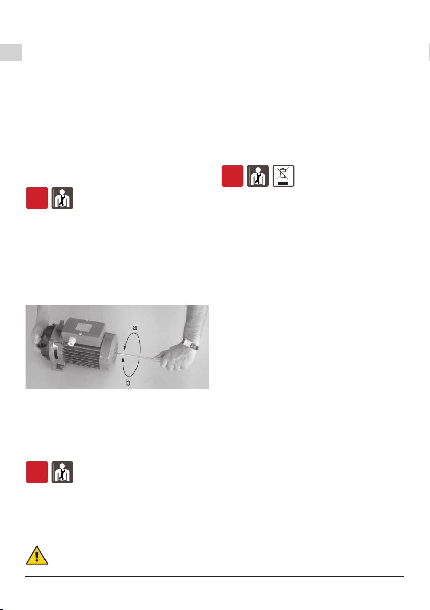
Al primo avviamento o dopo una lunga inattività,
controllare che l’albero giri a mano. Per questo scopo
le elettropompe hanno un intaglio per cacciavite
sull’estremità albero lato ventilazione.
Ruotare solo nel senso indicato dalle frecce sul corpo
pompa. Deve risultare una normale leggera resistenza
alla rotazione dovuta all’attrito della tenuta meccanica.
La pompa potrebbe essere bloccata da ostruzioni,
impurità, incollatura delle facce della tenuta meccanica
o per altre cause.
Se l’albero non si sblocca a mano occorre smontare la
pompa e pulirla.
Con alimentazione trifase vericare il senso di rotazione.
Non avviare il motore se l’albero risulta bloccato. La
girante potrebbe svitarsi se bloccata e se in questa
condizione il motore si avvia con senso di rotazione
inverso. La rotazione inversa è dannosa anche per la
tenuta meccanica.
Avviare per pochi giri il motore e controllare che il
senso di rotazione corrisponda a quello indicato dalle
frecce sul corpo pompa: orario guardando il motore dal
lato ventola.
In caso contrario togliere l’alimentazione elettrica e
invertire fra loro i collegamenti di due fasi.
Non lasciare mai cadere o introdurre oggetti su
qualsiasi apertura.
Non fare mai funzionare la pompa senza ltro di
protezione sull’apertura di aspirazione.
7.3. SPEGNIMENTO
ON
L’apparecchio deve essere spento in ogni caso
in cui vi fossero anomalie di funzionamento.
(vedi ricerca guasti).
Il prodotto è progettato per un funzionamento continuo,
lo spegnimento avviene solamente scollegando
l’alimentazione mediante i previsti sistemi di sgancio
(vedi par. “6.5 Collegamento elettrico”).
8. MANUTENZIONE
Prima di ogni intervento è obbligatorio mettere
l’apparecchio fuori servizio scollegando ogni fonte di
energia.
Se necessario rivolgersi ad elettricista o tecnico
esperto.
Ogni operazione di manutenzione, pulizia o
riparazione effettuata con l’impianto elettrico
sotto tensione, può causare gravi incidenti,
anche mortali, alle persone.
Se il cavo di alimentazione è danneggiato, esso
deve essere sostituito dal costruttore o dal suo
servizio assistenza tecnica o comunque da
una persona con qualica similare, in modo da
prevenire ogni rischio.
Nel caso di manutenzioni straordinarie, o di interventi
di manutenzione che necessitano lo smontaggio di
parti dell’apparecchio, il manutentore deve essere un
tecnico qualicato in grado di leggere e comprendere
schemi e disegni.
È opportuno tenere un registro di tutti gli interventi
effettuati.
i
Durante la manutenzione deve essere
posta particolare attenzione al ne di evitare
l’introduzione o l’immissione in circuito di
corpi estranei, anche di piccole dimensioni,
che possano causare un malfunzionamento e
compromettere la sicurezza dell’apparecchio.
Evitare di eseguire qualsiasi operazione a mani
nude. Utilizzare i guanti anti taglio, e resistenti
all’acqua, per lo smontaggio e la pulizia del
ltro o in altri particolari dove si rendessero
necessari.
i
Durante le operazioni di manutenzione non
deve essere presente personale estraneo.
Le operazioni di manutenzione non descritte in questo
manuale devono essere eseguite solamente da
personale specializzato inviato dalla CALPEDA S.p.A..
Per ulteriore informazioni tecniche riguardanti l’utilizzo
o la manutenzione dell’apparecchio, contattare
CALPEDA S.p.A..
8.1. Manutenzione ordinaria
OFF
Prima di ogni intervento di manutenzione
togliere l’alimentazione elettrica e assicurarsi
che la pompa non rischi di essere messa sotto
tensione per inavvertenza.
SPA Rev7.indd 5 08/02/19 17:46

IT
Pagina 6 / 28 SPA Rev7 - Istruzioni originali
Pulire regolarmente il ltro sulla bocca di aspirazione
nella vasca.
La pompa non richiede manutenzione salvo lo
smontaggio per la pulizia e rimozione di ostruzioni
dalle parti interne e del foro di drenaggio quando, col
tempo e con l’uso, si notasse una diminuzione delle
prestazioni o della capacità di autodrenaggio.
Evitare pulizie con getti d’acqua direttamente sulla pompa
installata senza i pannelli di protezione sulla vasca.
Dopo una lunga inattività, controllare che l’albero giri a
mano. Per questo scopo le elettropompe hanno un intaglio
per cacciavite sull’estremità albero lato ventilazione.
Ruotare solo nel senso indicato dalle frecce sul corpo
pompa. Deve risultare una normale leggera resistenza
alla rotazione dovuta all’attrito della tenuta meccanica.
La pompa potrebbe essere bloccata da ostruzioni,
impurità, incollatura delle facce della tenuta meccanica
o per altre cause.
Se l’albero non si sblocca a mano occorre smontare la
pompa e pulirla.
8.2. Smontaggio della pompa
OFF
Per lo smontaggio e il rimontaggio osservare la
costruzione sul disegno in sezione (pag. 14).
Per rimuovere il motore con il raccordo (32.00) dal
corpo pompa (14.00), togliere le viti (14.24), i dadi
(14.28) e le rosette (14.29) e fare leva con due
cacciaviti tra borchie diametralmente opposte.
Per smontare la girante (28.00) inserire un cacciavite
a lama larga nell’apposito intaglio sulla estremità
opposta dell’albero (78.00). Bloccare la girante con
una mano e svitarla ruotando l’albero con il cacciavite
in senso antiorario con azione torsionale di entrambe
le mani. (g. 3a).
Fig. 3 Smontaggio (a) e rimontaggio (b) girante
Se non è possibile bloccare o girare l’albero con
cacciavite, togliere la calotta (90.00) e la ventola
(88.00) e svitare la girante tenendo bloccato l’albero
con una chiave adatta.
Assieme alla girante si smonta la parte rotante della
tenuta meccanica (36.00).
8.3. Rimontaggio
OFF
Nel caso di sostituzione della tenuta meccanica
(36.00) montare la parte rotante della tenuta sul
mozzo della girante (28.00) spingendo la molla
no allo spallamento frontale in modo che risulti poi
correttamente compressa.
Per facilitare il montaggio della tenuta meccanica
lubricare il mozzo della girante, la sede della parte
ssa e gli anelli di tenuta con acqua pulita.
ATTENZIONE: con i tipi trifasi, per evitare
lo svitamento (e la rottura) della girante nel
caso di avviamento con senso di rotazione
invertito, pulire l’estremità lettata dell’albero
e applicare sulla metà anteriore del tratto
lettato Loctite 638 (per evitare lo svitamento
causato dalla forza resistente dell’acqua nel
caso di rotazione inversa).
Montare la girante sull’albero tenendola ferma con
una mano e avvitando l’albero in senso orario con
cacciavite no a bloccare la girante sullo spallamento
di arresto. Con questa operazione si mettono a
contatto le superci frontali della tenuta meccanica
senza farle strisciare fra loro (g. 3b).
Pulire con acqua la guarnizione O-ring (14.20) e le
superci di tenuta con le quali viene a contatto.
Al rimontaggio del gruppo motore con girante fare
attenzione che il riferimento sporgente all’interno del
corpo pompa (14.00) si inserisca nell’apposita feritoia
sul coperchio diffusore (27.00).
9. SMALTIMENTO
OFF
Direttiva europea
2012/19/EU (WEEE)
La demolizione dell’apparecchio deve essere afdata
ad aziende specializzate nella rottamazione di prodotti
metallici, per denire attentamente come procedere.
Per lo smaltimento devono essere seguite le
disposizioni di legge in vigore nel Paese in cui avviene
lo smantellamento, oltre che quanto previsto dalle
leggi internazionali per la protezione ambientale.
10. RICAMBI
10.1. Modalità di richiesta dei ricambi
Nelle eventuali richieste di parti di ricambio precisare
il numero di posizione nel disegno in sezione ed i dati
di targa.
L’ordine può essere inviato a CALPEDA S.p.A. tramite
telefono, fax, e-mail.
11. DENOMINAZIONE DELLE PARTI
Nr. Denominazione
14.00 Corpo pompa
14.20 O-ring
14.24 Vite
14.28 Dado
14.29 Rosetta
27.00 Coperchio diffusore
27.04 Parete diffusore
27.08 O-ring
28.00 Girante
36.00 Tenuta meccanica
70.00 Lanterna di raccordo
73.00 Cuscinetto
73.08 V-ring
76.00 Carcassa con avvolg.
76.04 Pressacavo
76.16 Appoggio
76.54 Morsettiera
78.00 Albero-rotore
81.00 Cuscinetto
81.04 V-ring
82.00 Coperchio motore
82.04 Molla di compensaz.
88.00 Ventola
90.00 Calotta
90.04 Vite
92.00 Tirante
94.00 Condensatore
94.02 Anello ferma cond.
98.00 Coperchio scat. mors
98.04 Vite
98.08 Guarnizione
Con riserva di modiche.
SPA Rev7.indd 6 08/02/19 17:46

IT
SPA Rev7 - Istruzioni originali Pagina 7 / 28
12. RICERCA GUASTI
OFF
ATTENZIONE: togliere la tensione di alimentazione prima di effettuare qualsiasi manovra.
Non far girare pompa e motore a secco nemmeno per un breve periodo.
Attenersi scrupolosamente alle nostre istruzioni per l’uso, se necessario rivolgersi ad un centro
assistenza autorizzato.
INCONVENIENTI
PROBABILI CAUSE POSSIBILI RIMEDI
1)
Il motore non si
avvia
a) Alimentazione elettrica non idonea
b) Collegamenti elettrici non corretti
c) Intervento del dispositivo di protezione
da sovraccarico del motore
d) Fusibili bruciati o difettosi
e) Albero bloccato
f) Se le cause di cui sopra sono già state
vericate, il motore potrebbe essere in
avaria
a) Vericare che la frequenza e la tensione di rete sia idonea alle
caratteristiche elettriche indicate in targhetta
b) Collegare correttamente il cavo di alimentazione alla morsettiera.
Vericare che la protezione termica sia impostata correttamente (vedi
dati sulla targhetta motore) e accertarsi che il collegamento del quadro
elettrico a monte del motore sia stato eseguito in modo corretto
c) Controllare l’alimentazione elettrica e accertarsi che l’albero della
pompa giri liberamente. Vericare che la taratura della protezione
termica sia stata eseguita correttamente (vedi targhetta motore)
d) Sostituire i fusibili, vericare l’alimentazione elettrica e quanto riportato
in a) e c)
e) Rimuovere le cause di bloccaggio come indicato in “Pompa bloccata”
f)
Riparare o sostituire il motore rivolgendosi ad un centro assistenza autorizzato
2)
Pompa
bloccata
a) Prolungati periodi di inattività con
formazione di ossido all’interno della
pompa
b) Ingresso di corpi solidi nella girante
della pompa
c) Cuscinetti bloccati
a) Lo sbloccaggio delle elettropompe monoblocco di piccola taglia si può
effettuare con un cacciavite agendo sull’apposito intaglio ricavato nella
parte posteriore dell’albero. Per gruppi di dimensioni maggiori si può
imprimere la rotazione direttamente dall’albero pompa o dal giunto (si
ricorda ancora di togliere prima l’alimentazione elettrica) o rivolgersi ad
un centro assistenza autorizzato
b) Se si è in grado, smontare il corpo pompa e rimuovere i corpi solidi
estranei all’interno della girante, se necessario rivolgersi a ad un centro
assistenza autorizzato
c) Nel caso si siano danneggiati i cuscinetti, sostituirli o se necessario
rivolgersi ad un centro assistenza autorizzato
3)
La pompa
funziona ma
non fornisce
acqua
a)
Possibile ingresso di aria da connessioni
del tubo di aspirazione, dai tappi di scarico
o riempimento della pompa oppure dalle
guarnizioni del tubo in aspirazione
b) Valvola di fondo otturata o tubo di
aspirazione non completamente
immerso nel liquido
c) Filtro in aspirazione otturato
a) Vericare quale particolare non è a tenuta e sigillare in modo più
efcace la connessione
b) Pulire o sostituire la valvola di fondo e impiegare un tubo di aspirazione
idoneo all’applicazione
c) Pulire il ltro, se necessario sostituirlo. Vedere anche punto 2a)
4)
Portata
insufciente
a) Tubazioni ed accessori con diametro
troppo piccolo che causano eccessive
perdite di carico
b) Presenza di depositi o corpi solidi nei
passaggi interni della girante
c) Girante deteriorata
d)
Rasamenti di girante e corpo pompa usurati
e) Viscosità eccessiva del liquido pompato
(se di natura diversa dall’acqua)
f) Senso di rotazione errato
g) Altezza di aspirazione eccessiva rispetto
alla capacità aspirante della pompa
h)
Eccessiva lunghezza del tubo di aspirazione
a) Usare tubi e accessori idonei all’impiego
b) Pulire la girante ed installare un ltro in aspirazione per evitare l’ingresso
di altri corpi solidi
c) Sostituire la girante, se necessario rivolgersi ad un centro assistenza
autorizzato
d) Sostituire la girante e il corpo pompa
e) La pompa non è idonea
f) Invertire i collegamenti elettrici nella morsettiera o nel quadro elettrico
g) Provare a chiudere parzialmente la saracinesca in mandata e/o
diminuire il dislivello tra pompa e liquido in aspirazione
h) Avvicinare la pompa al bacino di aspirazione in modo da usare
una tubazione più corta. Se necessario, adottare una tubazione di
aspirazione di diametro maggiore
5)
Rumore e
vibrazioni
della pompa
a) Parte rotante sbilanciata
b) Cuscinetti usurati
c) Pompa e tubazioni non ssate
saldamente
d) Portata troppo elevata per il diametro
della tubazione di mandata
e) Funzionamento in cavitazione
f) Alimentazione elettrica squilibrata
a) Vericare che corpi solidi non ostruiscano la girante
b) Sostituire i cuscinetti
c) Ancorare adeguatamente le tubazioni di aspirazione e mandata
d) Usare diametri superiori o ridurre la portata della pompa
e) Ridurre la portata agendo sulla saracinesca in mandata e/o impiegare
tubi con diametro interno maggiore. Vedere anche il punto 4h)
f) Vericare che la tensione di rete sia idonea
6)
Perdita dalla
tenuta
meccanica
a) La tenuta meccanica ha funzionato a
secco o si è incollata
b) Tenuta meccanica rigata per la presenza
di parti abrasive nel liquido pompato
c) Tenuta meccanica non idonea al tipo di
applicazione
d) Leggero gocciolamento iniziale durante
il riempimento o al primo avviamento
Nei casi a), b) e c), sostituire la tenuta, se necessario rivolgersi ad un
centro assistenza autorizzato
a) Accertarsi che il corpo pompa (e il tubo di aspirazione se la pompa
non è autoadescante) siano riempiti di liquido e che tutta l’aria sia stata
evacuata. Vedere anche il punto 5e)
b) Installare un ltro in aspirazione e impiegare una tenuta adatta alle
caratteristiche del liquido da pompare
c) Scegliere una tenuta con caratteristiche idonee al tipo di impiego
d) Aspettare che la tenuta si assesti con la rotazione dell’albero. Se il
problema persiste, vedere i punti 6a), 6b) o 6c) oppure rivolgersi ad un
centro assistenza autorizzato
SPA Rev7.indd 7 08/02/19 17:46

GB
Page 8 / 28 SPA Rev7 - Operating Instructions
THIS INSTRUCTION MANUAL IS THE PROPERTY
OF CALPEDA S.P.A. ANY REPRODUCTION, EVEN
IF PARTIAL, IS FORBIDDEN
1. GENERAL INFORMATION
Before using the product carefully read the information
contained in this instruction manual, the manual should
be kept for future reference.
Italian is the original language of this instruction
manual, this language is the reference language in
case of discrepancies in the translations.
This manual is part of the essential safety requirement
and must be retained until the product is nally de-
commissioned.
The customer, in case of loss, can request a copy
of the manual by contacting Calpeda S.p.A. or their
agent, specifying the type of product data shown on
the label of the machine (see 2.3 Marking)
Any changes, alterations or modications made to the
product or part of it, not authorized by the manufacturer,
will revoke the “CE declaration” and warranty.
This appliance should not be operated
by children younger than 8 years,
people with reduced physical, sensory
or mental capacities, or inexperienced
people who are not familiar with the
product, unless they are given close
supervision or instructions on how to
use it safely and are made aware by
a responsible person of the dangers
its use might entail. Children must not
play with the appliance.
It is the user's responsibility to clean
and maintain the appliance. Children
should never clean or maintain it
unless they are given supervision.
Read carefully the installation
section which sets forth:
-
Themaximum permissiblestructural
working pressure (chapter 3.1).
- The type and section of the
power cable (chapter 6.5).
- The type of electrical protection
to be installed (chapter 6.5).
1.1. Symbols
To improve the understanding of the manual, below are
indicated the symbols used with the related meaning.
Information and warnings that must be
observed, otherwise there is a risk that the
machine could damage or compromise
personnel safety.
The failure to observe electrical information
and warnings, could damage the machine or
compromise personnel safety.
i
Notes and warnings for the correct management
of the machine and its parts.
Operations that could be performed by the nal
user. After carefully reading of the instructions,
is responsible for maintenance under normal
conditions. They are authorized to affect
standard maintenance operations.
Operations that must be performed by a
qualied electrician. Specialized technician
authorised to affect all electrical operations
including maintenance. They are able to
operate with in the presence of high voltages.
Operations that must be done performed by
a qualied technician. Specialized technician
able to install the device, under normal
conditions, working during “maintenance”,
and allowed to do electrical and mechanical
interventions for maintenance. They must
be capable of executing simple electrical
and mechanical operations related to the
maintenance of the device.
Indicates that it is mandatory to use individual
protection devices.
OFF
Operations that must be done with the device
switched off and disconnected from the power
supply.
ON
Operations that must be done with the device
switched on.
1.2. Manufacturer name and address
Manufacturer name: Calpeda S.p.A.
Address: Via Roggia di Mezzo, 39
36050 Montorso Vicentino - Vicenza / Italia
www.calpeda.it
1.3. Authorized operators
The product is intended for use by expert operators
divided into end users and specialized technicians.
(see the symbols above).
i
It’s forbidden, for the end user, carry out
operations which must be done only by
specialized technicians. The manufacturer
declines any liability for damage related to the
non-compliance of this warning.
1.4. Warranty
For the product warranty refer to the general terms and
conditions of sale.
SUMMARY
1. GENERAL INFORMATION............................. 8
2. TECHNICAL DESCRIPTION.......................... 9
3. TECHNICAL FEATURES................................9
4. SAFETY.......................................................... 9
5. TRANSPORTATION AND HANDLING ......... 10
6. INSTALLATION.............................................10
7. STARTUP AND OPERATION ....................... 11
8. MAINTENANCE............................................ 11
9. DISPOSAL.................................................... 12
10. SPARE PARTS .............................................12
11. ESIGNATION OF PARTS ............................. 12
12. TROUBLESHOOTING..................................13
Drawing for dismantling and assembly.................. 26
Declaration of conformity....................................... 28
SPA Rev7.indd 8 08/02/19 17:46

GB
SPA Rev7 - Operating Instructions Page 9 / 28
i
The warranty covers only the replacement and
the repair of the defective parts of the goods
(recognized by the manufacturer).
The Warranty will not be considered in the following
cases:
-
Whenever the use of the device does not conform
to the instructions and information described in this
manual.
-
In case of changes or variations made without
authorization of the manufacturer.
- In case of technical interventions executed by a non-
authorized personnel.
- In case of failing to carry out adequate maintenance.
1.5. Technical assistance
Any further information about the documentation,
technical assistance and spare parts, shall be
requested from: Calpeda S.p.A. (paragraph 1.2).
2. TECHNICAL DESCRIPTION
Self-draining, single-impeller pumps, with motor
insulated from pumped water, constructed with high
quality, corrosion-proof plastic materials, with stainless
steel diffuser.
PVC pipe connections:
Ports for cementing joint, with external thread for union
coupling.
2.1. Intended use
For water circulation in spas, hydromassage bathtubs
and whirlpools.
For clean water with a maximum temperature of 60 °C
(140 °F).
Limit the water at the inlet to the bathtub to a
maximum temperature of 50 °C (122 °F).
Maximum water level in the bathtub or spa: 2,000 mm
above the pump.
2.2. Improper use
The device is designed and built only for the purpose
described in paragraph 2.1.
Improper use of the device is forbidden, as is
use under conditions other than those indicated
in these instructions.
Improper use of the product reduces the safety and
the efciency of the device, Calpeda shall not be
responsible for failure or accident due to improper use.
Do not use in ponds, tanks or swimming pools
or where people may enter or come into contact
with the water.
2.3. Marking
The following picture is a copy of the name-plate that is
on the external case of the pump.
1 Pump type
2 Delivery
3 Head
4 Rated power
5 Tension nominale
6
Nom. motor current
7 Notes
8 Fréquence
9 Operation Duty
10 Insulation class
11 Weight
12 Power factor
13
Rotation speed rpm
14 Protection
15 Serial number
16 Certications
Example plate pump
XXXXXXX
Q min/max X/X m3/h
XXXXXXX
H max/min X/X mIP XX
n XXXX/min
220∆/380Y V3~50Hz cosø X
X/X A
XXXXXXXX
S1 l.cl. XXkg
XkW (XHp) S.F.
1
2
3
4
5
6
7
8910
16
15
14
13
12
11
Montorso (VI) Italy IT 00142630243
Made in Italy
3. TECHNICAL FEATURES
3.1. Technical data
Dimensions and weight (see technical catalogue).
Nominal speed 2900/3450 rpm
Protection IP X5
Supply voltage / Frequency:
- up to 240V 1~ 50/60 Hz
- up to 480V 3~ 50/60 Hz
Check that the mains frequency and voltage
correspond to the electrical characteristics shown on
the indicator plate.
The electric data marked on the label are referred to
the nominal power of the motor.
Sound pressure: < 70 dB (A).
Max. starts per hour: 30 at regular intervals.
Maximum permissible pressure in the pump casing: 25
m (2,5 bar).
Maximum suction pressure: PN (Pa) - Hmax (Pa).
3.2. Operating conditions
Installation in well ventilated location protected from
the weather, with a maximum ambient temperature of
40 °C.
4. SAFETY
4.1. General provisions
Before using the product it is necessary to
know all the safety indications.
Carefully read all operating instructions and the
indications dened for the different steps: from
transportation to disposal.
The specialized technicians must carefully comply
with all applicable standards and laws, including local
regulations of the country where the pump is sold.
The device has been built in conformity with the current
safety laws. The improper use could damage people,
animals and objects.
The manufacturer declines any liability in the event of
damage due to improper use or use under conditions
other than those indicated on the name-plate and in
these instructions.
i
Follow the routine maintenance schedules and
the promptly replace damaged parts, this will
allows the device to work in the best conditions.
Use only original spare parts provided from Calpeda
S.p.A or from an authorized distributor.
Don’t remove or change the labels placed on
the device.
Do not start the device in case of defects or damaged
parts. Maintenance operations, requiring full or partial
disassembly of the device, must be done only
after disconnection from the supply.
4.2. Safety devices
The device has an external case that prevents any
contact with internal parts.
4.3. Residual risks
The appliance, designed for use, when used in-line with
the design and safety rules, doesn’t have residual risks.
4.4. Information and Safety signals
For this kind of product there will not be any signals
on the product.
SPA Rev7.indd 9 08/02/19 17:46

GB
Page 10 / 28 SPA Rev7 - Operating Instructions
4.5. Individual protection devices
During installation, starting and maintenance it is
suggested to the authorized operators to consider
the use of individual protection devices suitable for
described activities.
During ordinary and extraordinary maintenance
interventions, safety gloves are required.
Signal individual protection device
HAND PROTECTION
(gloves for protection against chemical,
thermal and mechanical risks).
5. TRANSPORTATION AND HANDLING
The product is packed to maintain the content intact.
During transportation avoid to stack excessive weights.
Ensure that during the transportation the box cannot
move.
It is not necessary to use any special vehicle to
transport the packaged device.
The transport vehicles must comply, for the weight and
dimensions, with the chosen product (see technical
catalogue dimensions and weights).
5.1. Handling
Handle with care, the packages must not receive
impacts.
Avoid to impact onto the package materials that could
damage the pump.
6. INSTALLATION
6.1. Dimensions
For the dimensions of the device (see technical
catalogue).
6.2. Ambient requirements and installation site
dimensions
The customer has to prepare the installation site in
order to guarantee the right installation and in order to
fulll the device requirements (electrical supply, etc...).
The place where the device will be installed must fulll
the requirements in the paragraph 3.2.
It's Absolutely forbidden to install the machine in an
environment with potentially explosive atmosphere.
6.3. Unpacking
i
Inspect the device in order to check any
damages which may have occurred during
transportation.
Package material, once removed, must be discarded/
recycled according to local laws of the destination
country.
6.4. Installation
The SPA pumps must be installed with the rotor
axis horizontal and feet downwards in piping layouts
in which the lling and draining of the pump
is obtained through the pipes, with lling and
draining of the bathtub or spa.
Whirlpool tubs must be constructed so that the
water cannot remain in the system after the tub
has been drained.
To allow for self-draining, mount the pump on a base
positioned at a level equal to or higher than the bathtub
or spa suction port and, to allow for lling, with the
delivery port positioned at a level lower than that for
normal lling (under the overow discharge).
Installation beneath the skirt of a bathtub or spa
which is closed externally with protection panels must
provide at least one slot with a 5-10 mm aperture
(preferably between the panel and the oor) suitable
for air recirculation for ventilation of the motor.
Mount the pump on a base located at least 40 mm
(11/2 inches) above the intended mounting surface.
For outdoor spas or whirlpools, the pump and electric
parts must be installed within an enclosure for
protection from the weather and ooding and installed
on a base located at least 100 mm (4 inches) above
the mounting surface.
Make sure installation allows access for servicing and
inspection, disassembly or replacement of the pump.
Follow standards for safety (some safety standards
are indicated in the section 6.5.).
6.4.1. Pipes
Connections of pipes to the pump ports.
Use pipes made of PVC type, plastic material.
The pump ports are designed to allow for direct
cemented joints (g. 1). The external thread allows for
connection with an optional, removable union coupling
(g. 2).
3.93.033/1
3.93.033/2
Fig. 1 Cemented joint.
3.93.033/1
3.93.033/2
Fig. 2 Threaded union coupling.
To join the pipe to the pump or to the union coupling,
use an adhesive or cement suitable for the ABS
material. Follow carefully the instructions of the
product chosen .
Tighten union couplings to the extent sufcient to
ensure a tight seal.
Avoid tightening too much as excessive torque may
damage the pump or the union couplings themselves.
Make sure all joints are properly sealed.
The diameter of the pipes must not be smaller than the
diameter of the pump ports.
Place a removable lter inside the bathtub or whirlpool
suction port.
The suction pipe must have a minimum length of
500 mm and must lead upwards from the bathtub or
whirlpool suction port to the pump suction port.The
delivery pipe must also be positioned to allow for
complete draining when the bathtub is drained .
SPA Rev7.indd 10 08/02/19 17:46

GB
SPA Rev7 - Operating Instructions Page 11 / 28
6.5. Electrical connection
OFF
Electrical connection must be carried out only
by a qualied electrician in accordance with
local regulations.
Follow safety standards EN 60335-2-41, EN 60335-
2-60 or UL 1795 and UL 1081and adopt all safety
measures indicated in installation standards.
The unit must be properly earthed (grounded).
Connect the earthing (grounding) conductor to the
terminal with the marking.
Compare the frequency and mains voltage with
the
name-plate data and connect the supply conductors
to the terminals in accordance with the appropriate
diagram inside the terminal box cover.
ATTENTION: never allow washers or other
metal parts to fall into the internal cable
opening between the terminal box and
stator. If this occurs, dismantle the motor to
recover the object which has fallen inside.
The exible power supply cord must be at least of the H05
RN-F or H05 VV-F type. For outdoor whirlpool or spas the
mains cable must be at least of the H07 RN-F type
with
section of cable not less than (par. 12.5 TAB 1).
All the electrical components must be located outside
the reach of individuals who use the pool and must be
positioned or attached without any risk of their falling
into the bathtub.
Make electric bonding connections.
Connect only to a circuit protected by a ground-fault
circuit-interrupter with a rated residual operating
current I∆N not exceeding 30 mA.
Install a device for disconnection from the mains
(switch) with a contact separation of at least 3 mm in
all poles.
With a three-phase motor install an overload protection
device with curve D appropriate for the rated current
of the pump.
Single-phase SPAM, are supplied with a capacitor
connected to the terminals and (for 220-240 V - 50 Hz)
with an incorporated thermal protector.
7. STARTUP AND OPERATION
7.1. Preliminary checks before start-up of the
pump
Do not start-up the device in case of damaged parts.
7.2. First starting
OFF
ATTENTION: never run the pump dry, not even for
a short trial run.
Start the pump when the bathtub has been lled.
Stop the pump before the bathtub is drained.
To avoid damage to the pump due to prolonged
operation in a no-water situation make sure the
installed unit has level detectors or sensors to impede
starting and to provide automatic stopping if there is no
water in the bathtub or install a timer to protect against
the risk of prolonged accidental operation.
At rst start-up or following a long idle period,
check that the shaft turns by hand.
For this purpose use the screwdriver notch on the shaft
end ventilation side. Turn the shaft by hand only in the
direction indicated by the arrows on the pump casing.
Note that a slight degree of resistence to rotation is
normal; this is due to friction caused by the mechanical
seal.
The pump might be jammed by an obstruction, foreign
matter, sticking of mechanical seal surfaces or other
causes.
If the shaft cannot be freed by hand, the pump will
have to be dismantled and cleaned.
With three-phase motors check the direction of
rotation.
Do not start the motor if the shaft is jammed. If
jammed, the impeller may unscrew should the
motor start rotating backwards. Reverse rotation
can also damage the mechanical seal.
Momentarily start the motor to make sure pump
shaft rotation corresponds to the direction indicated by
the arrows on the pump casing: rotation is clockwise
when viewing the shaft from the fan end.
Otherwise, disconnect electrical power and reverse
the connections of two phases.
Never drop or insert any object into any opening.
Do not operate this unit without the guard over the
suction tting.
7.3. Switch off of the pump
ON
The appliance must be switch off every time
there are faults. (see troubleshooting).
The product is designed for a continuous duty, the
switch off is performed by disconnecting the power
supply by means the expected disconnecting devices.
(see paragraph “6.5 Electrical connection”).
8. MAINTENANCE
Before any operations it's necessary to disconnect the
power supply.
If required ask to an electrician or to an expert
technician.
Every maintenance operations, cleaning or
reparation executed with the electrical system
under voltage, it could cause serious injuries
to people.
If the supply cord is damaged, it must be
replaced by the manufacturer, its service agent
or similarly qualied persons in order to avoid
a hazard.
In case of extraordinary maintenance, or maintenance
operations that require part-removing, the operator
must be a qualied technician able to read schemes
and drawings.
It is suggest to register all maintenance operation
executed.
i
During maintenance keep particular attention in
order to avoid the introduction of small external
parts, that could compromise the device safety.
It is forbidden to execute any operations with
the direct use of hands. Use water-resistant,
anti-cut gloves to disassemble and clean the
lter or in other particular cases.
i
During maintenance operations external
personnel is not allowed.
Maintenance operations that are not described in
this manual must be made only by special personnel
authorized by Calpeda S.p.A.
For further technical information regarding the use or
the maintenance of the device, contact Calpeda S.p.A.
8.1. Routine maintenance
OFF
Before every maintenance operations
disconnect the power supply and make sure
that the device could not accidentally operate.
SPA Rev7.indd 11 08/02/19 17:46

GB
Page 12 / 28 SPA Rev7 - Operating Instructions
Clean the lter inserted in the bathtub suction opening
at regular intervals.
The pump does not require servicing except for
disassembly for cleaning and removal of any
obstruction from inner parts and the draining hole
when, with use and in the course of time, performance
or self-draining capacity are found to be reduced.
Avoid cleaning an installed pump by hosing down
directly with jets of water without protection panels on
the bathtub.
Following a long idle period, check that the shaft
turns by hand.
For this purpose use the screwdriver notch on the shaft
end ventilation side. Turn the shaft by hand only in the
direction indicated by the arrows on the pump casing.
Note that a slight degree of resistence to rotation is
normal; this is due to friction caused by the mechanical
seal.
The pump might be jammed by an obstruction, foreign
matter, sticking of mechanical seal surfaces or other
causes.
If the shaft cannot be freed by hand, the pump will
have to be dismantled and cleaned.
8.2. Dismantling the pump
OFF
For dismantling and re-assembly see construction in
the cross-section drawing (page 14).
Remove the motor assembly with the lantern bracket
(32.00) from the pump casing (14.00), after removing
the screws (14.24), the nuts (14.28) and the washers
(14.29), levering them out with two screwsdrivers in
diametrically opposed positions.
To remove the impeller (28.00) insert a large straight-
blade screwdriver in the slot on the shaft (78.00) at the
ventilation end. Grip the impeller with one hand and
unscrew it, turning the shaft counter-clockwise and
twisting with both hands (g. 3a).
Fig. 3 Dismantling (a) and remounting (b) the impeller
If it is not possible to hold or move the shaft with the
screwdriver, remove the fan cover (90.00) and motor
fan (88.00) and unscrew the impeller by gripping the
shaft with a suitable wrench.
With the impeller the rotating part of the mechanical
seal (36.00) will remove.
8.3. Re-assembly
To replace the mechanical seal (36.00) t the rotating
part over the impeller hub (28.00) and push the
spring right down as far as the front shoulder. In this
way, correct spring compression will be ensured in
subsequent assembly.
Lubricate the seal with water and align the impeller on
the motor shaft.
ATTENTION: with the three-phase models, to avoid
the unscrewing (and breaking) of the impeller should
the motor start rotating backwards, clean the threaded
shaft end and apply on the rst half of the threaded part
Loctite 638 (to avoid unscrewing due to the resistant-
force of the water in the case of a backward rotation).
Grip the impeller with one hand and turn the shaft with
a screwdriver in the clockwise direction until tight.
With this operation the front surfaces of the mechanical
seal come into contact without rubbing against each
other during tightening.
Clean the O-ring (14.20) and seal surfaces with water.
When replacing the motor assembly with the impeller,
be careful to insert the locating lug inside the pump
casing (14.00) into the locating slot on the diffuser
cover (27.00).
9. DISPOSAL
OFF
European Directive
2012/19/EU (WEEE)
The nal disposal of the device must be done by
specialized company.
Make sure the specialized company follows the
classication of the material parts for the separation.
Observe the local regulations and dispose the device
accordingly with the international rules for environment
protection.
10. SPARE PARTS
10.1. Spare-parts request
When ordering spare parts, please quote their
designation, position number in the cross section
drawing and rated data from the pump name plate
(type, date and serial number).
The spare parts request shall be sent to CALPEDA
S.p.A. by phone, fax, e-mail.
11. ESIGNATION OF PARTS
Nr. Designation
14.00 Pump casing
14.20 O-ring
14.24 Screw
14.28 Nut
14.29 Washer
27.00 Diffuser cover
27.04 Diffuser wall
27.08 O-ring
28.00 Impeller
36.00 Mechanical seal
70.00 Lantern bracket
73.00 Ball bearing
73.08 V-ring
76.00 Motor casing with winding
76.04 Cable gland
76.16 Support
76.54 Terminal board
78.00 Shaft with rotor packet
81.00 Ball bearing
81.04 V-ring
82.00 Motor end shield
82.04 Compensating spring
88.00 Motor fan
90.00 Fan cover
90.04 Screw
92.00 Tie-bolt
94.00 Capacitor
94.02 Capacitor gland
98.00 Terminal box cover
98.04 Screw
98.08 Gasket
Changes reserved.
SPA Rev7.indd 12 08/02/19 17:46

GB
SPA Rev7 - Operating Instructions Page 13 / 28
12. TROUBLESHOOTING
OFF
WARNING: Turn off the power supply before performing any operations.
Do not allow the pump or motor to run when dry even for a short period.
Strictly follow the user instructions and if necessary contact an authorised service centre.
PROBLEM
PROBABLE CAUSES POSSIBLE REMEDIES
1)
The motor does
not start
1a) Unsuitable power supply
1b) Incorrect electrical connections
1c) Engine overload protective device cuts
in.
1d) Blown or defective fuses
1e) Shaft blocked
1f) If the above causes have already
been checked, the engine may be
malfunctioning
1a) Check that the mains frequency and voltage correspond to the
electrical characteristics shown on the indicator plate
1b) Connect the power supply cable to the terminal board correctly. Check
that the thermal overload protection is set correctly (see data on the
engine indicator plate) and make sure that the fuseboard upline of the
engine has been properly connected
1c) Check the power supply and make sure that the pump shaft is turning
freely. Check that the thermal overload protection has been set
correctly (see engine indicator plate)
1d)
Replace the fuses, check the electric power supply and points a) and c)
1e) Remove the cause of blockage as indicated in the “Blocked pump”
instruction booklet
1f) Repair or replace the engine by applying to an authorised service
centre
2)
Pump blocked 2a) Prolonged periods of inactivity with
formation of rust inside the pump
2b) Presence of solid bodies in the pump
rotor
2c) Bearings siezed
2a) Rotation may be started directly from the pump shaft or from the
joint (remember to turn off the electricity supply rst ) or contact an
authorised service centre
2b) If possible, dismantle the pump casing and remove any solid foreign
bodies inside the rotor, if necessary contact an authorised service
centre
2c) If the bearings are damaged replace them or if necessary contact an
authorised service centre
3)
The pump
functions
but no water
comes out
3a) Possible inltration of air from suction
tube connections, drain plugs or lling
of pump or from the gaskets of the
suction pipe
3b) Foot valve blocked or suction pipe not
fully immersed in liquid
3c) Suction lter blocked
3a) Check which part is not tight and seal the connection adequately
3b) Clean or replace the bottom valve and use a suction pipe suitable for
the application
3c) Clean the lter, if necessary, replace it . See point 2a) also.
4)
Insufcient ow 4a) Pipes and accessories with diameter
too small causing excessive loss of
head
4b) Presence of deposits or solid bodies in
the internal passages of the rotor
4c) Rotor deteriorated
4d) Worn rotor and pump case
4e) Excessive viscosity of the liquid
pumped (if other than water)
4f) Incorrect direction of rotation
4g) Suction head excessive in relation to
the suction capacity of pump
4h) Suction pipe too long
4a) Use pipes and accessories suitable for the specic application
4b) Clean the rotor and install a suction lter to prevent other foreign
bodies from entering
4c) Replace the rotor, if necessary, contact an authorised service centre
4d) Replace the rotor and the pump casing
4e) The pump is unsuitable
4f) Invert the electrical connections on the terminal board or control panel
4g) Try to close the feeder gate partially and/or reduce the difference in
level of the pump and the liquid being aspirated
4h) Bring the pump closer to the suction tank so as to use a shorter pipe.
If necessary use a pipe of a wider diameter
5)
Noise and
vibrations
from the pump
5a) Rotating part unbalanced
5b) Worn bearings
5c) Pump and pipes not rmly attached
5d) Flow too strong for the diameter of the
delivery pipe
5e) Functioning in cavitation
5f) Unbalanced power supply
5g) Incorrect alignment of pump-motor unit
5a) Check that no solid bodies are obstructing the rotor
5b) Replace the bearings
5c) Anchor the delivery and suction piping as needed
5d) Use bigger diameters or reduce the pump ow
5e) Reduce the ow by adjusting the feeder gate and/or using pipes with
a bigger internal diameter. See point 4g) too
5f) Check that the mains voltage is right
5g) If necessary, the unit must be re-aligned
6)
Leakage from
the mechanical
seal
6a) The mechanical seal has functioned
when dry or has stuck
6b) Mechanical seal scored by presence
of abrasive parts in the liquid pumped
6c) Mechanical seal unsuitable for the
type of application
6d) Slight initial drip during lling or on rst
start-up
In cases 6a), 6b) and 6c), replace the seal, if necessary contact an
authorised service centre
6a) Make sure that the pump casing (and the suction pipe if the pump is
not self-priming) are full of liquid and that all the air has been expelled.
See point 5 e) too.
6b) Install a suction lter and use a seal suited to the characteristics of the
liquid being pumped.
6c) Choose a seal with characteristics suitable for the specic application
6d)
Wait for the seal to adjust to the rotation of the shaft. If the problem
persists, see points 6a), 6b) or 6c) or contact an authorised service centre.
SPA Rev7.indd 13 08/02/19 17:46

D
Seite 14 / 28 SPA Rev7 - Betriebsanleitung
VORLIEGENDE GEBRAUCHSANLEITUNG IST
EIGENTUM VON CALPEDA S.p.A. JEGLICHE AUCH
TEILWEISE VERVIELFÄLTIGUNG IST VERBOTEN.
1. ALLGEMEINE INFORMATIONEN
Vor Gebrauch des Produkts sind die Hinweise und
die Anweisungen sorgfältig durchzulesen, welche in
diesem Handbuch geschrieben sind. Das vorliegende
Handbuch ist zum künftigen Nachschlagen aufzubewahren.
Dieses Handbuch wurde original auf Italienisch erfasst.
Bei Abweichungen zwischen Original und Übersetzung
ist das Original auf Italienisch ausschlaggebend.
Das Handbuch ist Bestandteil des Gerätes, garantiert
dessen Sicherheit und ist bis zur endgültigen
Entsorgung des Produkts aufzubewahren.
AufAnfrage vom Käufer liefertCalpeda S.p.A. Kopie des
vorliegenden Handbuchs im Falle von dessen Verlust.
Geben Sie bitte dabei die Produktenbezeichnung an,
welche auf der Etikette der Maschine geschrieben ist
(Ref. 2.3 Kennzeichnung).
Bei Änderungen, missbräuchlichen Eingriffen oder
unzulässigen Arbeiten an dem Gerät oder an dessen
Teilen, welche nicht vom Hersteller autorisiert wurden,
verliert die “EG-Erklärung” ihre Gültigkeit und die
Garantie erlischt.
Dieses Gerät darf von Kindern unter
Jahren bedient werden. Auch nicht von
Personen mit eingeschränkten physischen,
sensorischen oder geistigen Fähigkeiten
oder unerfahrene Menschen, die nicht mit
dem Produkt vertraut sind.
Es sei denn sie benden sich unter
strenger Aufsicht durch eine qualizierte
Person welche genaue Anweisung zur
sichern Bedienung des Gerätes gibt und
auf mögliche Gefahren durch den Einsatz
des Gerätes hinweist.
Kinder dürfen nicht mit dem Gerät spielen.
Es liegt in der Verantwortung des Bedieners
das Gerät zu Reinigen und zu Warten.
Kinder dürfen niemals das Gerät
Reinigen oder Warten, es sei denn
sie benden sich unter strenger,
qualizierter Aufsicht und Anleitung.
Lesen Sie sorgfältig den
Installationsabschnitt, welcher darlegt:
- Den maximale zulässigen
Gehäuseenddruck (Kapitel 3.1).
- Typ und Querschnitt des
Anschlusskabels. (Kapitel 6.5).
- Den Typ der zu installierenden
elektrischen Absicherung. (Kapitel 6.5).
1.1. Verwendete Symbole
Zum besseren Verstehen dieses Handbuchs werden die
darin verwendeten Symbole bzw. Piktogramme mit den
entsprechenden Bedeutungen im Folgenden aufgelistet.
Informationen und Hinweise, welche zu
beachten sind, um Beschädigungen an dem
Gerät oder Mängel an der Sicherheit des
Personals zu vermeiden.
Informationen und Hinweise über
elektrische Teile, deren Nichtbeachtung zu
Beschädigungen an dem Gerät oder Mängeln
an der Sicherheit des Personals führen kann.
i
Bemerkungen und Warnungen für einen
korrekten Betrieb des Gerätes und dessen
Komponenten.
Maßnahmen, welche vom Endverbraucher
des Gerätes vorgenommen werden dürfen.
Nachdem er die Gebrauchsanleitung
durchgelesen hat. Er ist dafür
verantwortlich, dass das Gerät in normalen
Gebrauchsbedingungen gehalten wird. Er
ist berechtigt, Maßnahmen der ordentlichen
Wartung vorzunehmen.
Maßnahmen, welche von einem qualiziertem
Elektriker vorzunehmen sind, welche in der
Lage sind, das Gerät zu installieren, es unter
normalen Umständen zu betrieben, es unter
Wartungsumständen funktionieren zu lassen.
Diese Techniker ist dazu berechtigt, Einstellungs-,
Wartungs- und Reparaturmaßnahmen an
elektrischen und mechanischen Teilen vorzunehmen.
Maßnahmen, welche von einem qualiziertem
Techniker vorzunehmen sind, welcher das Gerät
unter normalen Umständen korrekt betreiben kann
und dazu berechtigt ist, sämtliche Wartungs-,
Einstellungs- und Reparaturmaßnahmen an
mechanischen Teilen vorzunehmen.
Es ist obligatorisch, persönliche
Schutzausrüstungen zu tragen: Handschutz.
OFF
Maßnahmen, welche beim ausgeschalteten
und vom Stromnetz getrennten Gerät
vorzunehmen sind.
ON
Maßnahmen, welche beim eingeschalteten
Gerät vorzunehmen sind.
1.2. Firmenbezeichnung und Adresse vom Her-
steller
irmenbezeichnung: Calpeda S.p.A.
Adresse: Via Roggia di Mezzo, 39
36050 Montorso Vicentino - Vicenza / Italien
www.calpeda.it
1.3. Autorisiertes Bedienungspersonal
Dieses Gerät richtet sich an erfahrene Bediener, welche
Endverbraucher und spezialisierte Techniker sein können
(siehe Auistung der Symbole hier oben).
i
Dem Endverbraucher ist es strengstens verboten,
Maßnahmen vorzunehmen, welche ausschließlich
von spezialisierten Techniker durchgeführt werden
dürfen. Der Hersteller haftet nicht für Schäden, welche
aus der Nichtbeachtung dieses Verbotes resultieren
.
INHALTSVERZEICHNIS
1. ALLGEMEINE INFORMATIONEN................14
2. TECHNISCHE BESCHREIBUNG.................15
3. TECHNISCHE MERKMALE .........................15
4. SICHERHEITSMASSNAHMEN.................... 15
5. TRANSPORT UND HANDHABUNG ............ 16
6. AUFSTELLUNG............................................16
7. ANLAUF UND BETRIEB...............................17
8. WARTUNG....................................................17
9. ENTSORGUNG ............................................18
10. ERSATZTEILE..............................................18
11. TEILE-BENENNUNG....................................18
12. FEHLERBEHEBUNG....................................19
Zeichnung für Demontage und Montage............... 26
Konformitätserklärung ...........................................28
SPA Rev7.indd 14 08/02/19 17:46

D
SPA Rev7 - Betriebsanleitung Seite 15 / 28
1.4. Garantie
Bzgl. der Garantie über die Produkte muss man sich auf
die allgemeinen Verkaufsbedingungen beziehen.
i
Die Garantie umfasst den KOSTENLOSEN Ersatz
oder die KOSTENLOSE Reparatur der defekten Teile
(welche als defekt vom Hersteller anerkannt werden).
Die Garantie erlischt:
- Wenn das Gerät nicht unter Beachtung der Anweisungen
und Normen verwendet wird, welche in diesem Handbuch
beschrieben sind.
-
Wenn Änderungen am Gerät ohne Genehmigung seitens
des Herstellers vorgenommen werden (siehe Abschnitt 1.5).
- Wenn technische Servicemaßnahmen vom Personal
durchgeführt werden, welches nicht vom Hersteller
autorisiert worden ist.
-
Wenn die in diesem Handbuch beschriebenen
Wartungsmaßnahmen nicht beachtet werden.
1.5. Technisches Service
Für weitere Informationen über Dokumentation,
Service-Dienstleistungen und Geräteteile wenden Sie
sich bitte an: Calpeda S.p.A. (Abschnitt 1.2).
2. TECHNISCHE BESCHREIBUNG
Selbstentleerende, einstuge Kreiselpumpen mit
vom Badewasser getrennten Motor. Pumpe aus
hochwertigen, korrosionsbeständigen Kunststoffen,
mit Diffusor aus Edelstahl.
Anschluß von PVC-Rohren:
Stutzen für Preßsitzverbindung, mit Außengewinde für
Überwurfmutter.
2.1. Zweckentsprechende Verwendung
Zur Wasserumwälzung in Sprudelbadewannen und
Whirlpools.
Für reines Wasser mit einer Höchsttemperatur von 60 °C.
Die Wasser-Höchsttemperatur ist bei Einlauf
in die Hydromassagewanne auf 50 °C zu
begrenzen.
Zulässiger Wasser-Höchststand in der Wanne: 2.000
mm über der Pumpe.
2.2. Vernünftigerweise vorhersehbare Fehlan-
wendung
Das Gerät wurde ausschließlich zu den im Abschnitt 2.1
beschriebenen Zwecken entworfen und hergestellt.
Die Verwendung vom Gerät zu anderen
unzulässigen Zwecken oder unter in diesem
Handbuch nicht vorgesehenen Bedingungen ist
strengstens verboten.
Die Fehlanwendung des Produktes verringert seine
Sicherheits- und Efzienzmerkmale. Calpeda haftet nicht
für Mängel oder Unfälle, welche aus der Nichtbeachtung
der oben beschriebenen Verbote resultieren.
Dieses Gerät darf nicht in Teichen, Becken und
Schwimmbädern angewandt werden, wenn
Menschen im Wasser sind.
2.3. Kennzeichnung
Im Folgenden nden Sie eine Kopie des Kennschildes ,
welches am Außengehäuse der Pumpe angebracht ist.
1 Pumpentyp
2 Fördermenge
3 Förderhöhe
4 Nennleistung
5 Nennspannung
6 Nennstrom
7 Bemerkungen
8 Frequenz
9 Betriebsart
10 Isolationsklasse
11 Gewicht
12 Leistungssfaktor
13 Nenndrehzahl
14 Schutzart
15 Seriennummer
16 Konformität
Beispiel Typenschild der Pumpe
XXXXXXX
Q min/max X/X m3/h
XXXXXXX
H max/min X/X mIP XX
n XXXX/min
220∆/380Y V3~50Hz cosø X
X/X A
XXXXXXXX
S1 l.cl. XXkg
XkW (XHp) S.F.
1
2
3
4
5
6
7
8910
16
15
14
13
12
11
Montorso (VI) Italy IT 00142630243
Made in Italy
3. TECHNISCHE MERKMALE
3.1. Technische Daten
Abmessungen und Gewicht (siehe Katalog).
Nenndrehzahl 2900/3450 rpm
Schutzklasse IP X5
Netzspannung / Frequenz
- bis 240V 1~ 50/60 Hz
- bis to 480V 3~ 50/60 Hz
Prüfen Sie die vorhandene Spannung und Frequenz
auf Übereinstimmung mit den Daten auf dem
Typenschild des Motors.
Die elektrischen Daten auf dem Typenschild beziehen
sich auf die Nennleistung des Motors.
Schalldruck: < 70 dB (A).
Max. Anlaufzahl pro Stunde: 30 Starts.
Höchstzulässiger Pumpenenddruck: 25 m (2,5 bar).
Maximaler Saugdruck: PN (Pa) - Hmax (Pa).
3.2. Aufstellungsort der Pumpe
Einsatz nur in gut belüfteten und gegen
Witterungseinüsse geschützten Räumen.
Raumtemperatur bis 40 °C.
4. SICHERHEITSMASSNAHMEN
4.1. Allgemeine Verhaltensregeln
Vor Gerätegebrauch ist es wesentlich, alle
Sicherheitshinweise sorgfältig durchzulesen.
Lesen und beachten Sie alle technische Anweisungen,
Betriebsanleitungen und Hinweise über sämtliche
Arbeitsphasen, vom Transport bis zur endgültigen
Entsorgung, welche in diesem Handbuch geschrieben sind.
Die
spezialisierten Techniker sind dazu verpichtet,
sämtliche Regelungen, Normen und Gesetze zu
beachten, welche in dem Aufstellungsland gelten, wo
die Pumpe verkauft worden ist. Das Gerät entspricht
den geltenden Sicherheitsnormen.
Eine unsachgemäße Verwendung kann jederzeit zu
Schäden an Menschen, Tiere oder Sachen führen.
Der Hersteller schließt jegliche Haftung aus, falls
solche Schäden aus Betriebsbedingungen resultieren,
welche von den in diesem Handbuch bzw. am
Kennschild angegebenen Bedingungen abweichen.
i
Beachten Sie dieangegebenenWartungsfristen
und ersetzen Sie sofort alle beschädigte
oder verschlissene Teile. Dadurch wird das
Gerät immer unter den besten Bedingungen
funktionieren.
Bestellen Sie ausschließlich originale Ersatzteile,
welche von CALPEDA S.p.A. oder von den
autorisierten Händlern geliefert werden.
Entfernen oder ändern Sie die Kennschilder
nicht, welche am Gerät vom Hersteller
angebracht werden.
Das Gerät darf nicht betrieben werden, falls Mängel
oder Beschädigungen festzulegen sind.
Alle Wartungs- und Instandhaltungsarbeiten,
bei denen das Gerät völlig oder teilweise
abzumontieren ist, sind nur dann auszuführen,
wenn das Gerät vom Netz getrennt worden ist.
4.2. Sicherheitsvorrichtungen
Das Gerät besteht aus einem Außengehäuse, welches
jeglichen Kontakt mit den internen Getrieben verhindert.
4.3. Restrisiken
In Anbetracht seiner Auslegung und seines
Verwendungszwecks (und unter Beachtung von der
sachgemäßen Verwendung und den Sicherheitsnormen)
weist das Gerät keine Restrisiken auf.
4.4.
Sicherheits- und Informationskennzeichnung
Für diese Art Geräte ist keine Kennzeichnung am
Gerät vorgesehen.
SPA Rev7.indd 15 08/02/19 17:46

D
Seite 16 / 28 SPA Rev7 - Betriebsanleitung
4.5. Persönliche Schutzausrüstungen (PSA)
Bei der Installation, dem Anlauf und der Wartung ist es
für das Bedienerpersonal empfehlenswert, geeignete
Schutzausrüstungen aufgrund der durchzuführenden
Arbeit zu tragen.
Bei Wartungs- und Instandhaltungsarbeiten, sind
Schutzhandschuhe unbedingt zu tragen.
Piktogramm Obligatorische PSA
HANDSCHUTZ
(Schutzhandschuhe zum Schutz vor chemischen,
thermischen und mechanischen Risiken)
5. TRANSPORT UND HANDHABUNG
Das Produkt ist verpackt, damit der Inhalt nicht
beschädigt wird.
Beim Transport ist die Stapelung von schweren
Verpackungen zu vermeiden. Vergewissern Sie sich,
dass sich die Verpackung beim Transport nicht frei
bewegen kann.
Keine besonderen Mittel sind notwendig, um das
verpackte Gerät zu transportieren.
Die Mittel zum Transport des verpackten Gerätes
müssen für die Abmessungen und das Gewicht des
gekauften Produktes geeignet sein (siehe Katalog
Gesamtabmessungen).
5.1. Handhabung
Heben Sie die Verpackung sorgfältig, damit dem darin
gelegenen Gerät keine Schläge zugefügt werden.
Legen Sie auf die Verpackung kein weiteres Material,
welches der Pumpe beschädigen könnte.
6. AUFSTELLUNG
6.1. Gesamtabmessungen
Die Gesamtabmessungen des Gerätes (siehe Katalog)
angegeben.
6.2. Umgebungsbedingungen und Raumbedarf
am Aufstellungsort
Der Aufstellungsort ist entsprechend und mit Bezug
auf dessen Besonderheiten vorzubereiten, damit die
Installation reibungslos erfolgen kann (elektrische
Anschlüsse, usw.).
Die Umgebung, in der das Gerät aufgestellt wird, muss
den im Abschnitt 3.2 beschriebenen Anforderungen
entsprechen.
Es ist strengstens verboten, die Maschine in
explosionsgefährdeten Bereichen aufzustellen und in
Betrieb zu nehmen.
6.3. Auspacken
i
Überprüfen Sie, ob das Gerät beim Transport
beschädigt worden ist.
Das Verpackungsmaterial ist nach Auspacken der
Maschine laut der Gesetze und Vorschriften zu
entsorgen bzw. wieder zu verwerten, welche in dem
Aufstellungsland der Maschine gelten.
6.4. Einbau
Die Pumpen SPA werden mit der Welle in waagerechter
Position und Montege-füßen unten aufgestellt. Sie
sind für Anlagen vorgesehen, wo die Pumpen-
Auffüllung und-Entleerung über die Leitungsrohre
bei anschließender Auffüllung und Entlee-rung der
Wanne erfolgt.
Sprudelbadegeräte müssen so gebaut sein, daß
nach Entleerung der Wanne kein Wasser im
System verbleiben kann.
Um die Selbstentleerung sicherzustellen, wird die
Pumpe auf eine Grundplatte montiert, die sich auf
gleichem Niveau bzw. über der Saugöffnung der
Wanne bendet; um die Auffüllung sicherzustellen,
mit der Druckleitung auf einem unter dem normalen
Auffüllpegel liegenden Niveau (unter dem Überlauf).
Der Einbau unter dem außen mit Schutztafeln
geschlossenem Wannenrand muß mindestens einen
Öffnungsspalt von 5-10 mm aufweisen (vorzugsweise
zwischen Tafel und Fußboden), damit die Luft zur
Motorventilation zirkulieren kann.
Die Pumpe wird auf eine mindestens 40 mm über der
Einbauoberäche bendliche Grundplatte montiert. Bei
im Freien installierten Wannen bzw. Whirlpools sind
Pumpe und elektrische Teile vor Sonneneinstrahlung,
Wetterunbilden und Überschwemmungen zu
schützen. Die Pumpe ist auf eine mindestens 100 mm
über der Einbauober-äche bendliche Grundplatte zu
installieren.
Die Pumpe ist so zu installieren, daß Inspektio-nen,
Ausbau und ein eventueller Austausch der Pumpe
möglich ist.
Die Sicherheitsvorschriften DIN VDE 0700 Teil 60
(EN 60335-2-60) sind zu beachten.
6.4.1. Rohrleitungen
Anschluß der Rohrleitungen an die Pumpenöffnungen.
Rohre aus PVC-Kunststoff sind zu verwenden.
Die Pumpenöffnungen sind für den Direktanschluß
durch Preßsitzverbindung vorgesehen (Abb. 1).
Durch das Außengewinde ist der Anschluß mit optionaler
Überwurfmutter (ausbaubar) möglich (Abb. 2).
3.93.033/1
3.93.033/2
Abb. 1 Preßsitzverbindung.
3.93.033/1
3.93.033/2
Abb. 2 Anschluß mit Überwurfmutter.
Zur Preßsitzverbindung des Rohrs an der Pumpe oder
an der Überwurfmutter ist ein Kleber zu verwenden,
der für ABS-Material geeignet ist. Die Hinweise zur
Produktverwendung sind sorgfältig zu beachten.
Die Überwurfmuttern sind nur soweit anzuziehen,
bis die Dichtigkeit sichergestellt ist.
Ein übermässiges Anziehen kann die Pumpe oder die
Überwurfmuttern beschädigen.
Überprüfen, daß alle Verbindungen vollständig dicht
sind.
Der Leitungsdurchmesser darf nicht kleiner sein als
der Durchmesser der Pumpenöffnungen.
In die Saugöffnung der Wanne ist ein ausziehbares
Sieb einzubauen.
Die Länge des Saugrohrs muß mindestens 500 mm
betragen und von der Saugöffnung der Wanne bis zur
Saugöffnung der Pumpe ansteigend verlaufen. Auch
die Druckleitung muß so installiert werden, daß sie
sich mit dem Entleeren der Wanne vollständig entleert.
SPA Rev7.indd 16 08/02/19 17:46

D
SPA Rev7 - Betriebsanleitung Seite 17 / 28
6.5. Elektrischer Anschluß
OFF
Der elektrischeAnschluß ist von Fach-personal
unter Beachtung der örtlichen Vorschriften
auszuführen.
Die Sicherheitsvorschriften DIN VDE 0700 Teil 1,
DIN VDE 0700 Teil 60, DIN VDE 0100 Teil 701 bzw.
Teil 702 sind zu befolgen und alle Schutzmaßnahmen
der Einbauvorschriften anzuwenden.
Schutzleiter an die Erdungsklemme anschließen.
Netzspannung und -frequenz mit den Angaben auf dem
Typenschild vergleichen und Speiseleiter gemäß dem
Schaltbild im Klemmenkastendeckel anschließen.
ACHTUNG! Keine Scheibe oder andere
metallische Gegenstände in den internen
Leitungsdurchgang zwischen Klemmenkasten
und Stator fallen lassen. Andernfalls Motor
demontieren und Gegenstand beseitigen.
Das biegsame Speisekabel muß mindestens dem Typ
H05 RN-F bzw. H05 VV-F entsprechen. Für Anlagen im
Freien muß das Speisekabel mindestens dem Typ H07
RN-F entsprechen (DIN VDE 0100 Teil 737 beachten)
mit
Kabelquerschnitt nicht unter (Kap. 12.5 TAB 1)
.
Alle elektrischen Komponenten müssen sicher vor den
Wannenbenutzern untergebracht und so befestigt sein,
daß sie nicht in die Wanne fallen können.
Die Potentialausgleich-Anschlüsse sind auszuführen.
An einem Schaltkreis anschließen, der durch eine
Fehlerstromschutzeinrichtung mit I∆N ≤ 30 mA
geschützt ist.
Es ist eine Vorrichtung zur Abschaltung jeder Phase
vom Netz (Schalter) mit einem Öffnungsabstand der
Kontakte von mindestens 3 mm zu installieren.
Bei Dreiphasen-Drehstrommotoren ist ein
Motorschutzschalter
mit Kurve D
gemäß der
Stromaufnahme laut Typenschild vorzusehen.
Die Einphasen-Wechselstrompumpen SPAM, werden
bei mit angeschlossenem Anlaufkondensator im
Klemmenkasten und (bei 220-240 V - 50 Hz) mit
eingebautem Thermoschalter geliefert.
7. ANLAUF UND BETRIEB
7.1. Kontrollen vor dem Einschalten
Das Gerät darf nicht betrieben werden, falls
Beschädigungen festzulegen sind.
7.2. Erstanlauf
OFF
ACHTUNG!Die Pumpe darf nicht ohne Flüssigkeitsfüllung,
auch nicht probeweise, betrieben werden
.
Die Pumpe wird nach dem Auffüllen der Wannegestartet
und vor dem Entleeren abgeschaltet.
Zur Vermeidung von Schäden an der Pumpe durch
Trockenbetrieb ist sicherzustellen, daß die Anlage
entweder Pegelsonden bzw. -sensoren hat, die den Start
verhindern und die bei Wassermangel in der Wanne einen
automatischen Stop auslösen oder daß sie mit einem
Timer gegen zufälligen Dauerbetrieb ausgestattet ist.
Bei der ersten Inbetriebnahme bzw. nach längerem
Stillstand ist zu kontrollieren, daß sich die Welle von Hand
drehen läßt. Zu diesem Zweck haben die Elektropumpen
einen Einschnitt für den Schraubenzieher auf dem
Wellenende, Ventilations-seite.
Nur in Pfeilrichtung laut Pumpengehäuse drehen.
Aufgrund des Abriebs der Gleitringdichtung ist ein leichter
Drehwiderstand normal.
Die Pumpe könnte durch Verstopfungen, Verunreini-
gungen, Verklebungen der Stirnseiten der Gleitring-
dichtung oder andere Ursachen blockiert sein.
Wenn die Welle sich nicht von Hand löst, muß die Pumpe
ausgebaut und gereinigt werden.
Bei Dreiphasen-Drehstromversorgung ist die
Drehrichtung zu überprüfen.
De Motor darf nicht geschaltet werden, wenn die Welle
blockiert ist. Das Laufrad könnte sich lösen, wenn
es blockiert ist und wenn der Motor unter diesen
Bedingungen in umgekehrter Drehrichtung startet.
Die umgekehrte Drehung ist auch für die Gleitringdichtung
schädlich.
Den Motor kurz für einige Umdrehungen starten und
kontrollieren, ob die Drehrichtung der Pfeilrichtung auf dem
Pumpengehäuse entspricht: im Uhrzeigersinn (Motor von
Lüfterrad aus gesehen).
Andernfalls die Netzversorgung unterbrechen und zwei
beliebige Phasen im Motorklemmenkasten vertauschen.
Keine Gegenstände in die Öffnungen fallen lassen bzw.
einführen.
Die Pumpe nie ohne Schutzsieb auf der Saugöffnung
betreiben.
7.3. AUSSCHALTEN
ON
Das Gerät wurden so ausgelegt, dass es
ohne Unterbrechungen weiter funktionieren
kann. Die Ausschaltung erfolgt nur, wenn
das Gerät anhand der entsprechenden
Entkopplungsvorrichtungen vom Netz getrennt
wird (siehe Abs. 6.5 Elektrischer Anschluss).
8. WARTUNG
Vor jeglicher Wartungsarbeit ist das Gerät außer Betrieb
zu setzen und
es von jeglicher Energiequelle zu trennen.
Wenden Sie sich beim Bedarf an einen erfahrenen
Elektriker oder Techniker.
Wartungs-, Reparatur- oder Reinigungsarbeiten,
welche bei elektrischer Anlage unter Spannung
erfolgen, können zu schwerwiegenden, auch
tödlichen Unfällen für die Menschen führen.
Wenn das Stromkabel beschädigt ist, darf es,
um jedwede Gefahr zu vermeiden, nur vom
Hersteller, dem Kundendienst oder ähnlich
qualizierten Personen ausgetauscht werden.
Bei Instandsetzungsarbeiten oder Wartungsarbeiten, bei
denen Teile der Maschine abmontiert werden müssen,
muss das Wartungspersonal entsprechend qualiziert und
in der Lage sein, Schaltpläne und -bilder auszulegen.
Es ist empfehlenswert, jegliche durchgeführten
Wartungsarbeiten aufzuzeichnen.
i
Bei der Wartung ist besondere Aufmerksamkeit zu
schenken, damit keine auch kleinen Fremdkörper
in die Maschine eindringen, welche zum
Fehlfunktionieren oder zu Sicherheitsmängeln
führen könnten.
Nehmen Sie keine Arbeit ohne Schutzhandschuhe
vor. Tragen Sie schnittfeste und wasserdichte
Handschuhe beim Abmontieren und Reinigen des
Siebs oder von anderen Komponenten.
i
Der Zugang zur Maschine ist unbefugtem Pers
onal
während der Ausführung von Wartungsarbeiten
strengstens verboten.
Alle Wartungsarbeiten, welche in diesem Handbuch
nicht beschrieben sind, sind ausschließlich vom
spezialisierten Personal vorzunehmen, welches direkt
von CALPEDA S.p.A. gesendet wird.
Wenden Sie sich an CALPEDA S.p.A. für weitere
technische Informationen über das Gebrauch oder die
Wartung des Gerätes.
8.1. Ordentliche Wartung
OFF
Vor jeglicher Wartungsarbeit ist das Gerät vom
Stromnetz zu trennen und sicherzustellen,
dass die Pumpe nicht unerwünscht wieder
unter Spannung gesetzt werden darf.
SPA Rev7.indd 17 08/02/19 17:46

D
Seite 18 / 28 SPA Rev7 - Betriebsanleitung
Das Sieb auf der Saugöffnung in der Wanne ist
regelmäßig zu reinigen.
Die Pumpe erfordert keine Wartungsarbeiten mit Aus-
nahme des Ausbaus zur Reinigung und zur Verstop-
fungsbeseitigung in den Innenteilen und vom Draina-
geloch, wenn man im Lauf der Zeit und des Gebrauchs
eine Verminderung der Leistungen bzw. der Selbsten-
tleerungsfähigkeit feststellt.
Eine Reinigung mit Wasserstrahl direkt auf die
ohne Wannen-Schutztafeln installierte Pumpe ist zu
vermeiden.
Nach längerem Stillstand ist zu kontrollieren, daß sich die
Welle von Hand drehen läßt. Zu diesem Zweck haben die
Elektropumpen einen Einschnitt für den Schraubenzieher
auf dem Wellenende, Ventilations-seite.
Nur in Pfeilrichtung laut Pumpengehäuse drehen.
Aufgrund des Abriebs der Gleitringdichtung ist ein leichter
Drehwiderstand normal.
Die Pumpe könnte durch Verstopfungen, Verunreini-
gungen, Verklebungen der Stirnseiten der Gleitring-
dichtung oder andere Ursachen blockiert sein.
Wenn die Welle sich nicht von Hand löst, muß die Pumpe
ausgebaut und gereinigt werden.
8.2. Demontage der Pumpe
OFF
Demontage und Montage unter Zuhilfenahme des
Schnittbildes (Seite 14) durchführen.
Zur Trennung des Motors mit der Antriebslaterne
(32.00) vom Pumpengehäuse (14.00) sind die
Schrau-ben (14.24) mit Muttern (14.28) und Scheiben
(14.29) zu lösen. Das Pumpengehäuse ist danach
zwischen den gegenüberliegenden Ansätzen mit
zwei Schrau-benziehern abzudrücken. Danach kann
das Laufrad (28.00) demontiert werden. Dafür einen
breiten Schraubendreher in die vorgesehene Nut auf
der gegenüberliegenden Ventilatorseite der Welle
(78.00) stecken. Laufrad mit einer Hand halten und
durch Drehen der Welle mit dem Schraubendreher im
Gegenuhrzeigersinn abschrauben (Abb. 3a).
Abb. 3 Demontage (a) und Neumontage (b) des Laufrades
Falls die Welle nicht mit einem Schraubendreher
gedreht oder gehalten werden kann, Haube (90.00)
und Lüfterrad (88.00) abnehmen, Welle mit einem
geeignetem Schlüssel blockieren und so das Laufrad
abschrauben.
Zusammen mit dem Laufrad wird der rotierende Teil
der Gleitringdichtung (36.00) demontiert.
8.3. Zusammenbau
Falls die Gleitringdichtung (36.00) zu ersetzen ist, den
rotierenden Gleitring auf der Laufrad-nabe montieren
und die Feder bis zur Stirn-schulter drücken, damit ein
korrekter Sitz ge-währleistet ist.
Gleitringdichtung mit Wasser befeuchten.
ACHTUNG! Um bei den dreiphasigen
Pumpen ein Lösen des Laufrads (und
demzufolge den Bruch) bei Pumpenanlauf
in falscher Drehrichtung zu vermeiden, ist
das Wellen-ende am Gewinde zu säubern und
auf der vorderen Hälfte Loctite 638 (um ein
Lösen des Laufrads bei falscher Drehrichtung
aufgrund der Trägheit der Wasserfüllung zu
vermeiden).
Das Laufrad wird auf die Welle montiert, indem es
mit einer Hand festgehalten und die Welle mit einem
Schraubendreher im Uhrzeigersinn angeschraubt
wird, bis das Laufrad auf dem Anschlag blockiert ist.
Mit diesem Montagevorgang treten die Stirnä-chen
der Gleitringdichtung in Kontakt, ohne au-feinander
zu schleifen. (Nicht am Laufrad drehen, da sonst die
Stirnächen beschädigt werden können).
Runddichtring (14.20) und deren Dichtungsä-chen
mit Wasser reinigen.
Bei der Montage vom Motor mit Lau-frad sich
versichern, daß die Nase im Pumpengehäuse
(14.00) in der Nut des Diffusor-Deckels (27.00)
einrastet.
9. ENTSORGUNG
OFF
Europäischer Richtlinie
2012/19/EU (WEEE)
Die Verschrottung des Gerätes muss durch
Unternehmen erfolgen, welche auf der Verschrottung
von Metallprodukten spezialisiert sind.
Bei der Entsorgung sind sämtliche einschlägige
Vorschriften zu beachten, welche im Aufstellungsland
der Maschine gelten, sowie alle internationale
Umweltschutzvorschriften.
10. ERSATZTEILE
10.1. Ersatzteilebestellung
Bei der Bestellung von Ersatzteilen sind Bezeichnung,
Positionsnummer auf der Schnittaussicht und
die Daten auf dem Kennschild (Typ, Datum und
Kennnummer) anzugeben.
Die Bestellung kann telefonisch, per Fax oder per
E-Mail an CALPEDA S.p.A. gesendet werden.
11. TEILE-BENENNUNG
Nr. Teile-Benennung
14.00 Pumpengehäuse
14.20 Runddichtung
14.24 Schraube
14.28 Mutter
14.29 Scheibe
27.00 Diffusor-Deckel
27.04 Diffusor-Wand
27.08 Runddichtung
28.00 Laufrad
36.00 Gleitringdichtung
70.00 Antriebslaterne
73.00 Wälzlager
73.08 V-Ring
76.00 Motorgehäuse mit Wicklung
76.04 Kabelführung
76.16 Stütze
76.54 Klemmenbrett
78.00 Welle mit Rotorpaket
81.00 Wälzlager
81.04 V-Ring
82.00 Motorlagergehäuse
82.04 Federscheibe
88.00 Lüfterrad
90.00 Lüfter-Haube
90.04 Schraube
92.00 Verbindungschraube
94.00 Kondensator
94.02 Sicherungsring für Kond.
98.00 Klemmenkastendeckel
98.04 Schraube
98.08 Flachdichtung
Änderungen vorbehalten.
SPA Rev7.indd 18 08/02/19 17:46

D
SPA Rev7 - Betriebsanleitung Seite 19 / 28
12. FEHLERBEHEBUNG
OFF
WARNUNG: Vor jeglichen Arbeiten an der Pumpe oder dem Motor, unbeding Stromversorgung
abschalten!
Die Pumpe darf nicht, (auch nicht kurzzeitig) ohne Fördermedium betrieben werden.
Die Bedienungsanleitung ist genau zu beachten. Falls erforderlich einen autorisierten Serviepartner
hinzuziehen.
FEHLER MÖGLICHE URSACHEN MÖGLICHE FEHLERBESEITUNG
1)
Der Motor
startet nicht
1a) Falsche Spannungsversorgung.
1b) Falscher elektrischer Anschluss.
1c)
Motorschutzeinrichtung(Schutzschalter)
hat ausgelös.
1d) Sicherungen defekt oder ausgelöst.
1e) Welle blockiert.
1f) Falls alle zuvor genannten
Möglichkeiten überprüft wurden, liegt
evtl. ein defekt des Motors vor.
1a) Prüfen Sie die vorhandene Spannung und Frequenz auf
Übereinstimmung mit den Daten auf dem Typenschild des Motors.
1b) Anschluss der Stromversorgung überprüfen und ggf. korrigieren.
Prüfen, ob der Schutzschalter richtig eingestellt ist (Daten auf
Typenschild beachten). Die Verbindungen des Motorkabels zum
Schaltschrank auf korrekten Anschluss überprüfen.
1c)
Spannungsversorgung überprüfen. Prüfen, ob die Motorwelle sich leicht
drehen lässt. Den Motorschutzschalter auf korrekte Einstellung überprüfen
(Bitte beachten Sie hierzu die Daten auf dem Typenschild des Motors).
1d) Sicherungen austauschen, Spannungsversorgung sowie Punkte a)
+ c) prüfen.
1e) Ursache für das Blockieren beseitigen wie unter Pos. 2) "Pumpe
blockiert" beschrieben.
1f) Austausch oder Reparatur des Motors durch einen authorisierten
Servicepartner.
2)
Pumpe
blockiert
2a) Nach längerem Stillstand blockieren
Ablagerungen das Laufrad der
Pumpe.
2b) Feststoffe in der Pumpenkammer
blockieren die Läufereinheit.
2c) Lager fest.
2a)
Größere Maschinen können direkt an der Welle oder der Kupplung freigedreht
werden. (Unbedingt zuerst Spannungsversorgung zur Abschalten).
Gegebenenfalls einen authorisierten Servicepartner hinzuziehen.
2b)
Falls möglich, Pumpengehäuse demontieren und Festkörper entfernen.
Gegebenenfalls einen authorisierten Servicepartner hinzuziehen.
2c) Defekte Lager ersetzen. Gegebenenfalls einen authorisierten
Servicepartner hinzuziehen.
3)
Die Pumpe
läuft, jedoch
wird kein
Wasser
gefördert
3a)
Lufteintritt an der Saugleitung oder den
Beffüll-, Entleerungsschrauben oder
Dichtungen der saugseitigen Verrohrung.
3b) Fußventil blockiert oder Saugleitung
nicht vollständig eingetaucht.
3c) Saugseitiger Filter verstopft.
3a) Undichte Stelle suchen und vollständig abdichten, oder Saugleitung
ersetzen.
3b) Fußventil reinigen oder ersetzen. Saugleitung an die Förderleistung der
Pumpe anpassen.
3c) Filter reinigen oder falls erforderlich ersetzen. Siehe auch Punkt 2a).
4)
Zu geringe
Fördermenge
4a) Verrohrung und Armaturen mit zu
kleiner Nennweite verusachen zu
große Verluste.
4b) Feststoffe oder Ablagerungen im
Laufrad oder Pumpengehäuse.
4c) Laufrad defekt.
4d) Verscheiß an Laufrad und/oder
Gehäuse.
4e) Erhöhte Viskosität des
Fördermediums.
4f) Falsche Drehrichtung.
4g) Tatsächliche Saughöhe übersteigt die
maximale Saughöhe der Pumpe.
4h) Saugleitung zu lang.
4a) Verwenden Sie Verrohrung und Armaturen entsprechend Ihrer
Anwendung.
4b) Pumpe reinigen, Feststoffe entfernen. Gegebenenfalls saugseitigen
Filter installieren, um das Eindringen weiterer Verschmutzung zu
verhindern.
4c)
Laufrad ersetzen, evtl. einen authorisierten Servicepartner hinzuziehen.
4d) Laufrad und Pumpengehäuse ersetzen.
4e) Pumpe kann nicht verwendet werden, authorisierten Servicepartner
hinzuziehen.
4f) Elektrischen Anschluss überprüfen und Verdrahtung korrigieren.
4g) Druckseitiges Absperrventil teilweise schließen oder Saughöhe
verringern. Gegebenenfalls einen authorisierten Servicepartner
hinzuziehen.
4h) Länge der Saugleitung verringern, Pumpe näher an den Zulauftank
bringen. Eventuell Saugleitung mit größerem Querschnitt verwenden.
5)
Ungewöhnliche
Geräusche und
Vibration der
Pumpe
5a) Unwucht der Läufereinheit.
5b) Motolager defekt.
5c) Pumpe und Rohrleitung nicht xiert.
5d) Fördermenge zu groß für die
vorhandene Rohrleitung.
5e) Kavitation .
5f) Fehler der Spannungsversorgung.
5g) Falschausrichten des Pumpen-Motor-
Aggregats
5a) Prüfen, ob sich Feststoffe im Laufrad benden.
5b) Lager ersetzen.
5c) Pumpe und Rohrleitung xieren.
5d) Leitungen mit größerem Durchmesser verwenden oder Durchuß
verringern.
5e) Durch druckseitiges eindrosseln, Fördermenge reduzieren und / oder
saugseitige Rohrleitung mit größerem Querschnitt verwenden. Siehe auch
Punkt 4g).
5f) Überprüfen der Spannungsversorgung (Siehe Typenschild des Motors).
5g) Falls notwendig, ist das Aggregat neu auszurichten.
6)
Undichtigkeit
an der
Wellenabdichtung
6a) Defekt infolge von Trockenlauf oder
verkleben der Gleitächen.
6b) Gleitächen duch abrasive Partikel
defekt, Riefenbilden, Einlaufspuren.
6c) Falsche Gleitringdichtung für die
vorliegende Anwendung gewählt.
6d) Tropfenbildung and der
Wellenabdichtung beim Befüllen
der Pumpe. Zu geringer
Leitungsquerschnitt.
Im Falle von 6a), 6b) und 6c), Wellenabdichtung ersetzen Gegebenenfalls
einen authorisierten Servicepartner hinzuziehen.
6a)
Sicherstellen, dass die Pumpe (bei Normalsaugenden Pumpen auch die
Saugleitung) vollständig gefüllt und entlüftet ist. Siehe auch Punkt 5 e).
6b) Saugseitigen Filter installieren und ggf. Auswahl einer speziellen
Wellenabdichtung für das Fördermedium
6c) Auswahl einer Abdichtung für die vorhandene Anwendung
6d) Warten bis sich die Dichtung beim Start ausgerichtet hat. Falls das
Problem weiter besteht siehe Punkt 6a), 6b) or 6c) oder kontaktieren
Sie Ihren Service-partner
SPA Rev7.indd 19 08/02/19 17:46

RU
Cтраница 20 / 28 SPA Rev7 - Инструкции по эксплуатации
НАСТОЯЩЕЕ РУКОВОДСТВО ЯВЛЯЕТСЯ
СОБСТВЕННОСТЬЮ КОМПАНИИ CALPEDA S.P.A. ЛЮБОЕ
ВОСПРОИЗВЕДЕНИЕ, ДАЖЕ ЧАСТИЧНОЕ, ЗАПРЕЩЕНО.
1. ОБЩАЯ ИНФОРМАЦИЯ
Перед использованием изделия следует
внимательно ознакомиться с мерами
предосторожности и инструкциями, приведенными
в настоящем руководстве, которое должно
сохраняться для использования в будущем.
Оригинальный язык редакции - итальянский,
который будет главным при выяснении
несоответствий перевода.
Руководство является неотъемлемой частью
изделия, существенной для безопасности и должно
сохраняться до конца срока службы изделия.
Покупатель может запросить экземпляр тех. руководства
при потере, обратившись в компанию Calpeda S.p.A.
и указав тип изделия, приведенный на этикетке
оборудования (Смотри Раздел 2.3 “Маркировка”).
В случае изменений, порчи или внесения
изменения в изделие или его части без
разрешения завода-изготовителя “Декларация
CE” прекращает действовать и вместе с ней
гарантия на изделие.
Данный электроприбор может быть
использован детьми не младше
8 лет и лицами с ограниченными
физическими сенсорными или
умственными способностями или не
обладающими достаточным опытом
или знанием о работе подобного
прибора, под наблюдением или
после обучения безопасному
пользованию прибором и усвоения
связанных с ним опасностей.
Не разрешайте детям играть
с прибором. Чистка и уход за
прибором должны выполняться
пользователем. Не поручать чистку
и уход детям без контроля.
Внимательно читайте раздел по
установке, в котором указано
следующее:
- Максимально допустимый напор
в корпусе насоса (Глава 3.1).
- Тип и сечение кабеля питания.
(Глава 6.5).
- Тип электрической защиты, которая
должны быть установлена. (Глава 6.5).
1.1. Обозначения
Для улучшения восприятия используются символы/
пиктограммы, приведенные ниже с соответствующими
значениями.
Информация и меры предосторожности,
которые следует соблюдать. При
несоблюдении они могут привести к
повреждению изделия или нарушению
безопасности персонала.
Информация и меры предосторожности по
электрической безопасности, при несоблюдении
которых может быть повреждено изделие или
нарушена безопасность персонала
.
i
Примечания и предупреждения для
правильной эксплуатации изделия и его
компонентов.
Операции, которые могут выполняться конечным
пользователем изделия: пользователь
изделия
должен ознакомиться с инструкциями и несет
ответственность за их соблюдение в нормальных
условиях работы. Он может выполнять операции
по текущему тех. обслуживанию.
Операции, которые должны выполняться
квалифицированным электриком:
специализированный техник, допущенный к
выполнению операций по тех. обслуживанию
и ремонту электрической части. Может
работать с компонентами под напряжением.
Операции, которые должны выполняться
квалифицированным техником:
специализированный техник, способный
правильно использовать изделие в
нормальных условиях, допущенный к
выполнению операций по тех. обслуживанию,
регулировке и ремонту механической части.
Указывает на обязательное использование
средств индивидуальной защиты - защита
рук.
OFF
Операции, которые должны выполняться
при выключенном аппарате с его
отсоединением от электропитания.
ON
Операции, которые должны выполняться
при включенном аппарате.
1.2. Название компании и адрес завода-
изготовителя
Название компании: Calpeda S.p.A.
Адрес: Via Roggia di Mezzo, 39
36050 Montorso Vicentino - Vicenza / Italia
www.calpeda.it
1.3. Операторы с допуском
Изделие может использоваться опытными
операторами, которые подразделяются на конечных
пользователей изделия и специализированных тех.
специалистов (смотри символы выше).
i
Конечный пользователь не может
выполнять операции, предусмотренные
только для специализированных тех.
специалистов. Завод-изготовитель не
отвечает за повреждения, возникающие
при несоблюдении этого запрета.
УКАЗАТЕЛЬ
1. ОБЩАЯ ИНФОРМАЦИЯ ............................ 20
2. ТЕХНИЧЕСКОЕ ОПИСАНИЕ .....................21
3. ТЕХНИЧЕСКИЕ ХАРАКТЕРИСТИКИ........ 21
4. БЕЗОПАСНОСТЬ........................................ 21
5. ТРАНСПОРТ И ПЕРЕМЕЩЕНИЕ ..............22
6. УСТАНОВКА................................................22
7. ПУСК И РАБОТА.........................................23
8. ТЕХ. ОБСЛУЖИВАНИЕ..............................23
9. УДАЛЕНИЕ .................................................. 24
10. ЗАПАСНЫЕ ЧАСТИ .................................... 24
11. НАЗВАНИЕ КОМПОНЕНТОВ ....................24
12. Поиск неисправностей............................... 25
Чертеж для демонтажа и сборки ......................26
Декларация соответствия.................................. 28
SPA Rev7.indd 20 08/02/19 17:46
Other manuals for SPA
1
Table of contents
Languages:
Other Calpeda Water Pump manuals

Calpeda
Calpeda NM User manual

Calpeda
Calpeda BS V EMT Series User manual

Calpeda
Calpeda SPA User manual

Calpeda
Calpeda NCE GF Series User manual

Calpeda
Calpeda SD Series User manual

Calpeda
Calpeda CT61 User manual

Calpeda
Calpeda NGX User manual

Calpeda
Calpeda N User manual

Calpeda
Calpeda NMD Series User manual

Calpeda
Calpeda NC Series User manual
Popular Water Pump manuals by other brands

Little Giant
Little Giant WRS-5 manual

Checkpoint
Checkpoint 1250E Series operating manual

Checkpoint
Checkpoint GX15G11C3 Series operating manual

Aqua Medic
Aqua Medic DC Runner Series Operation manual

Astral Pool
Astral Pool BX Series owner's manual

Wilo
Wilo VeroLine-IPL Series Installation and operating instructions