cam SHP Series User manual

Original
operating manual
Flexibility & experience
SHP sideshifter
SHP-series
Operating manual
04/2022 – V01

2/36
© 04-2022. CAM attachments is a trademark of TVH Parts Holding NV, Brabantstraat 15, B-8790 Waregem. All rights reserved. No part of this publication may
be reproduced or communicated in any form or by any means, electronic or mechanical, including copying, recording or use in an information storage
or retrieval system, without prior and explicit permission of TVH Parts Holding NV. Printing errors reserved. Photographs and illustrations are included for
reference purposes only.
Responsible editor: TVH Parts Holding NV, Brabantstraat 15, BE-8790Waregem
TVH is a supplier of after-market spare parts and accessories that are suitable for the maintenance and repair of OEM equipment.

3/36
www.tvh.com/SHP_RV01
BG Bulgarian
Можете да намерите това ръководство на Вашия език чрез линка, посочен по – долу.
CS Czech
Tento návod najdete ve svém jazyce prostřednictvím odkazu níže.
DA Danish
Du kan finde denne vejledning på dit sprog via nedenstående link.
DE German
Sie finden diese Bedienungsanleitung in Ihrer Sprache unter folgendem Link.
EL Greek
Μπορείτε να βρείτε αυτό το εγχειρίδιο στη γλώσσα σας μέσω του παρακάτω συνδέσμου.
EN English
You can find this manual in your language via below link.
ES Spanish
Encontrarás este manual en tu propio idioma a través del siguiente enlace.
ET Estonian
Oma emakeelse juhendi leiate allolevalt lingilt.
FI Finnish
Löydät tämän manuaalin omalla kielelläsi alla olevan linkin taka.
FR French
Vous trouverez ce manuel dans votre langue via le lien ci-dessous.
GA Irish
Tá an lámhleabhar seo ar fáil i do theanga tríd an nasc thíos.
HR Croatian
Ovaj prirucnik mozete pronaci na svom jeziku putem donjeg linka.
HU Hungarian
Ez a kézikönyv az Ön nyelvén az alábbi link alatt található.
IS Icelandic
Hægt er að finna þessa handbók á þínu tungumáli á tenglinum hér að neðan.
IT Italian
Cliccando sul link sottostante troverai il manuale nella tua lingua.
LT Lithuanian
Šį vadovlėlį savo kalba rasite spustelėję žemiau esančią nuorodą.
LV Latvian
Rokasgrāmatu latviešu valodā Jūs varat atrast izmantojot zemāk esošo saiti.
MT Maltese
Tista’ssib dan il-manwal bil-lingwa tiegħek permezz tal-link ta’hawn taħt.
NL Dutch
Je vindt deze handleiding in jouw taal via onderstaande link.
NO Norwegian
Du finner denne håndboken på ditt språk via linken nedenfor.
PL Polish
Niniejsza instrukcja obsługi dostępna jest w Twoim języku za pośrednictwem poniższego linku.
PT Portuguese
Pode encontrar este manual no seu idioma através do link abaixo.
RO Romanian
Puteți găsi acest manual în limba dvs. prin link-ul de mai jos.
SK Slovak
Manuál vo vašom jazyku môžete nájst v priloženom vysvietenom riadku.
SL Slovenian
Ta priročnik najdete v svojem jeziku preko spodnje povezave.
SV Swedish
Du kan hitta denna manual på ditt språk via länken nedan.
TR Turkish
Bu kılavuzu aşağıdaki bağlantıdan kendi dilinizde bulabilirsiniz.

4/36
Thank you for using our product. For your safety and to ensure a correct operation, we would like to
bring to your attention some aspects of this manual:
• This booklet supplies useful instructions for the correct operation and maintenance of the product.
It is therefore necessary to pay the utmost attention to all of the paragraphs that illustrate the most
simple and secure way to operate and use this product.
• This booklet must be considered an integral part of the machine and must be included with the
deed of sale.
• Neither this publication, nor part of it, can be reproduced without written authorisation on the part
of the manufacturer.
• All of the information reported herein is based on data available at the moment of printing;
the manufacturer reserves the right to carry out modifications to its own products at any moment,
without notice and without incurring in any sanction. It is therefore suggested to always check for
possible updates.
The person responsible for the use of the product must make sure that all of the safety rules in force in
the country of its use are applied, to guarantee that the equipment is used in conformity with the use
for which it is destined and to avoid any dangerous situation for the user.
The following warning signs are used in this manual to warn you for dangers and risks:
Informative, be careful.
Warning, can lead to injury and damage if instructions aren’t followed.
Danger, can lead to serious or fatal injury and serious damage if instructions aren’t
followed.
The following conventions are used in this manual:
1 2
4
3
56
1 Right
2Left
3 Bottom
4Top
5 Front
6 Back

5/36
CONTENTS
1. INTRODUCTION ..................................................................................................... 6
2. DESCRIPTION ........................................................................................................ 7
2.1. Technical data......................................................................................................................7
2.2. Operating pressure and oil flow rate......................................................................................8
2.3. Main components of the product .........................................................................................8
2.4. Placement of the decals. . . . . . . . . . . . . . . . . . . . . . . . . . . . . . . . . . . . . . . . . . . . . . . . . . . . . . . . . . . . . . . . . . . . . . . . . . . . . . . . . . . . . . . . . . . . . . . . . . . . . . . . 9
2.5. Type plate..........................................................................................................................10
3. SAFETY INSTRUCTIONS .........................................................................................11
3.1. Explanation of the safety decals ..........................................................................................11
3.2. General safety instructions..................................................................................................11
4. TRANSPORT AND STORAGE....................................................................................13
5. ASSEMBLY AND INSTALLATION...............................................................................14
5.1. Packing list.........................................................................................................................14
5.2. Safety instructions for assembly and installation of the product............................................14
5.3. Installation of the product ..................................................................................................14
6. OPERATION..........................................................................................................19
6.1. Safety instructions for operating the product.......................................................................19
6.2. Operating instructions. . . . . . . . . . . . . . . . . . . . . . . . . . . . . . . . . . . . . . . . . . . . . . . . . . . . . . . . . . . . . . . . . . . . . . . . . . . . . . . . . . . . . . . . . . . . . . . . . . . . . . . . 20
7. MAINTENANCE .....................................................................................................22
7.1. Safety instructions for the maintenance of the product........................................................22
7.2. Maintenance schedule .......................................................................................................22
7.3. Maintenance instructions ...................................................................................................23
8. TROUBLESHOOTING..............................................................................................26
9. FINAL DECOMMISSIONING AND DISPOSAL ..............................................................27
10. ANNEXES .............................................................................................................28
10.1. CE certificate......................................................................................................................28
10.2. Hydraulic diagram..............................................................................................................30
10.3. Spare parts list....................................................................................................................31

6/36
1. INTRODUCTION
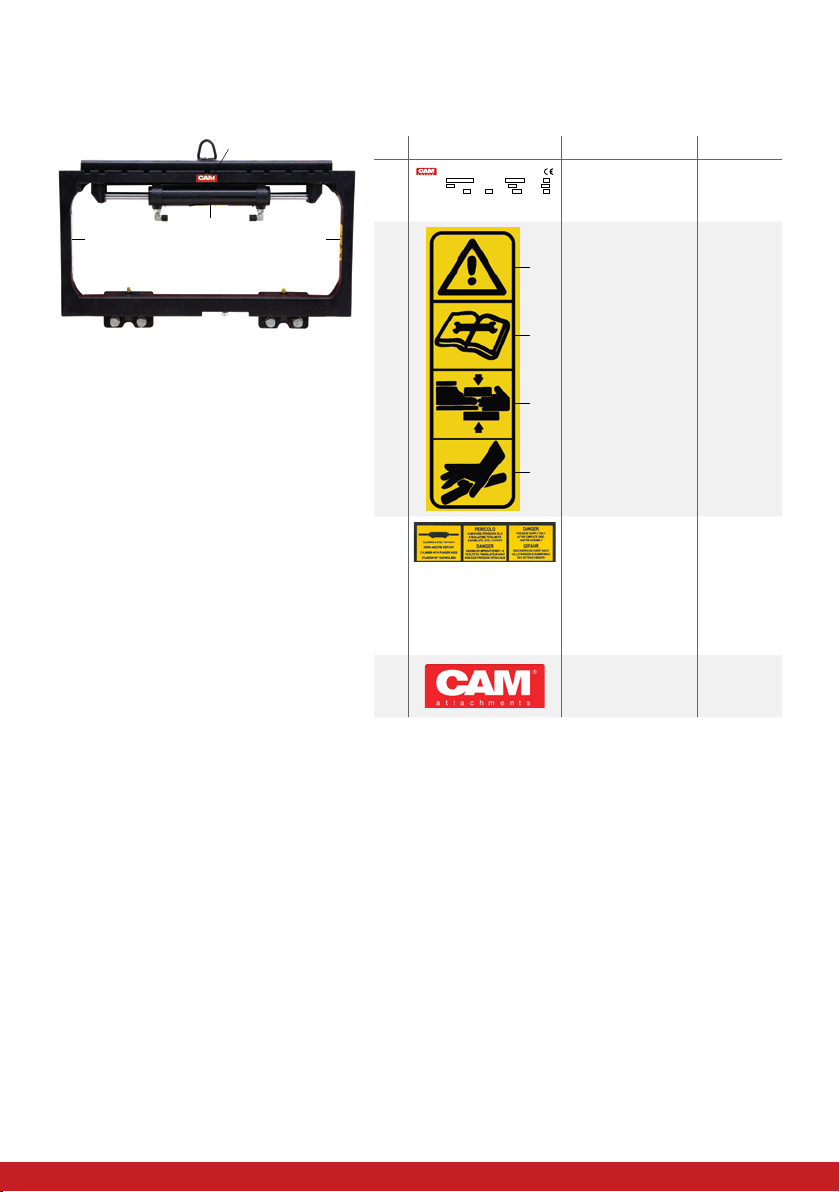
This manual contains all the necessary information on the installation and operation of the SHP
sideshifter.
Some of the maintenance operations should only be carried out by professional technicians.
If you require this information and the maintenance steps, please contact your dealer. Also included in
this manual are a number of safety instructions to create a safe working environment.
With a sideshifter you can shift a load from side to side for faster, more accurate lifting and placement.
This makes it possible to reduce your overall handling time, reduce damage to pallets and products
and increase your manoeuvrability, even through tight corners.
Check your machine manual to make sure you opt for the sideshifter with the correct load capacity.
Do not use this product for any other purposes.
Please read the manual thoroughly and observe the safety procedures before putting the unit into
operation. The operator and all persons who come into contact with the equipment should read the
manual carefully and regularly and have access to it at all times.
Keep this manual near the equipment and in a safe place for future reference!
Contact your dealer for any further questions or concerns you may have.
We guarantee a long period of trouble free operation if the unit is operated and maintained correctly.
We hope you will enjoy working with your SHP sideshifter.
This sideshifter may be unsafe if adequate maintenance is neglected. Therefore, adequate
maintenance facilities, trained personnel and procedures should be provided.
Maintenance and inspection shall be performed conform to the following practices:
1. A scheduled planned maintenance, lubrication and inspection system should be followed
(see maintenance instructions chapter 7).
2. Only qualified and authorised personnel shall be permitted to maintain, repair, adjust, and
inspect the sideshifter.
3. Modifications and additions which affect capacity and safe operation shall not be
performed by the customer or user without the manufacturers, prior written approval.
Capacity, operation and maintenance plates or decals shall be changed accordingly.
4. If modifications are made without written approval of the manufacturer, warranty will no
longer apply.
Any person in charge of putting the machine into operation, the operation itself or the
maintenance of the machine is urged to carefully read and observe the following instructions.
Make sure that the operators of this product are familiar with the safety instructions and follow
all the procedures. Neglecting these instructions can risk injury or death.

7/36
2. DESCRIPTION
2.1. Technical data
Always check the type plate for the correct information.
Model Capacity W4 W6 LL HCG VCG Weight ISO2328
kg/mm mm mm mm mm mm kg
Sideshifters ISO/FEM 2 with sliding pads
SHP225.080P.CD1 2500/500 800 780 58 23 224 42 2
SHP225.090P.CD1 2500/500 900 780 58 23 224 46 2
SHP225.092P.CD1 2500/500 920 780 58 23 224 46 2
SHP225.094P.CD1 2500/500 940 780 58 23 224 47 2
SHP225.098P.CD1 2500/500 980 780 58 23 224 48 2
SHP225.100P.CD1 2500/500 1000 780 58 23 224 49 2
SHP225.102P.CD1 2500/500 1020 780 58 23 224 49 2
SHP225.104P.CD1 2500/500 1040 780 58 23 224 50 2
SHP225.107P.CD1 2500/500 1070 780 58 23 224 51 2
SHP225.110P.CD1 2500/500 1100 780 58 23 224 52 2
SHP225.115P.CD1 2500/500 1150 780 58 23 224 54 2
SHP225.125P.CD1 2500/500 1250 980 58 23 224 57 2
SHP225.140P.CD1 2500/500 1400 980 58 23 224 67 2
Sideshifters ISO/FEM 3 with sliding pads
SHP335.100P.CD1 3500/500 1000 980 68 29 281 67 3
SHP335.102P.CD1 3500/500 1020 980 68 29 281 67 3
SHP335.107P.CD1 3500/500 1070 980 68 29 282 70 3
SHP335.110P.CD1 3500/500 1100 980 68 29 282 71 3
SHP335.115P.CD1 3500/500 1150 980 68 29 283 73 3
SHP335.120P.CD1 3500/500 1200 980 68 29 284 75 3
SHP335.125P.CD1 3500/500 1250 980 68 29 285 77 3
SHP335.130P.CD1 3500/500 1300 980 68 29 285 86 3
SHP335.135P.CD1 3500/500 1350 1080 68 29 286 89 3
SHP335.140P.CD1 3500/500 1400 1080 68 29 287 90 3
W4
W6
300
M16x2 mm depth 39 mm (2x)
15
////
HCG
VCG
LL
ISO 2328

8/36
2.2. Operating pressure and oil flow rate
Model Operating pressure Oil flow rate Hydraulic
functions
Minimum
Recommended
Maximum Minimum
Recommended
Maximum
bar bar bar l/min l/min l/min
SHP225 130 160 220 4 10 15 1
SHP335 130 160 220 6 12 18 1
A flow rate less than recommended will result in a lower rotating speed.
A flow rate greater than the maximum can result in excessive heating, reduced system
performance and reduced hydraulic system life.
2.3. Main components of the product
3
3
2
1
4 5
6
N° Component
1Cylinder connection
2 Cylinder
3Lifting hook
4Sliding pads
5 Frame
6Locking tab
42

9/36
2.4. Placement of the decals
The safety and warning labels should be placed as described in the pictures below. See chapter 3 for
the explanation of the safety warnings. If the decals are damaged or missing, replace them.
3
4
1 2
N° Decal Explanation Reference
1XXXXX.XXXX.XXXXXXXXXX
CATALOGUENUMBER
NO.D’IDENTIFICATION
KATALOGNUMMER
CATALOGUSNUMMER
NUMERODE REFERENCIA
NUMERODI CATALOGO
DONOT EXCEED THE LIFT TRUCK RES IDUALCAPACITY • DE RESTCAPACITEIT VAN DE HEFTRUCK MAG NIET OVERSCHRED ENW ORDEN • DIE RESTKA PAZITATDESGABELSTAPLERS DARF NICHT UBE RSCHRITTEN WERDEN •
NEPAS DEPASSER LA CAPACITE RESIDUELLE DU CHARIOT ELEVATEUR • NO EXCEDER LA C APACIDAD RESIDUAL DE LA CARRETILLA ELEVADORA • NON S UPERARELA PORTATARESIDUA DEL CARRELLO EL EVATORE
RATEDCAPACITY
CAPACITENOMINALE
NENNTRAGFAHIGKEIT
NOMINALECAPACITEIT
CAPACIDADNOMINAL
PORTATANOMINALE
kg
XXXXXX
WEIGHT
MASSE
MASSE
GEWICHT
PESO
MASSA
kg
XXXXXX
THICKNESS
EPAISSEUR
DICKE
DIKTE
ESPESOR
SPESSORE
mm
XXXX
RECOMMENDEDOPERATING PRESSUR E
PRESSIOND’UTILISATION RECOMMANDE
ANBEFOHLENARBEIT DRUCK
AANBEVOLENWERKDRUK
PRESIONOPERATIVA RECOMENDADA
PRESIONEDI ESERCIZIO R ACCOMANDATA
bar
XXXX
MAXIMUM
MAXIMA
MASSIMA
bar
XXXX
VERTICAL
VERTICAL
VERTICAL
VERTICAAL
VERTICAL
VERTICALE
mm
XXXXX
HORIZONTALCENTRE O F GRAVITY
CENTREDE GRAVITE HORIZO NTAL
HORIZONTALEIGENSCHWERPUNKT
HORIZONTAALZWAARTEPUNT
CENTRODE GR AVIDADH ORIZONTALE
CENTRODI GR AVITAORIZZONTALE
mm
XXXXX
SERIALNUMBER
NO.DE SERIE
SERIENNUMMER
SERIENUMMER
NUMERODE SERIE
NUMERODI SERIE
XXXXX/XX/XXXXX
YEAR
ANNE
JAHR
JAAR
ANO
ANNO
XXXX
Manufactured outside the EU for:
TVH PARTS HOLDING NV
Brabantstraat 15 • B-8790Waregem
www.camattachments.com With this type plate
you can identify
your product
166TA5424
2
1
2
3
4
1. Warning
2. Important:
Carefully read
the manual
before using the
equipment and
carrying out the
maintenance
operations
3. Important: Risk
of limb crushing
4. Important:
Pressurised
liquids
165TA4750
3Cylinder with
plunger rods.
Danger: Pressure
supply only
after complete
sideshifter
assembly
166TA5960
4CAM attachments
logo
Contact
your dealer

10/36
2.5. Type plate
N° Explanation
1CAM attachments logo
2Equipment capacity
3Equipment name
4 Address
5Horizontal centre of gravity
6Serial number
7CE logo
8Year of construction
9Equipment centre of gravity
10 Thickness
11 Recommended operating pressure
12 Maximum operating pressure
13 Equipment weight
XXXXX.XXXX.XXXXXXXXXX
CATALOGUE NUMBER
NO. D’IDENTIFICATION
KATALOG NUMMER
CATALOGUS NUMMER
NUMERO DE REFERENCIA
NUMERO DI CATALOGO
DO NOT EXCEED THE LIFT TRUCK RESIDUAL CAPACITY • DE RESTCA PACITEIT VAN DE HEFTRUCK MAG NIET OVERSCHREDEN WORDE N • DIE RESTK APAZITAT DES GABELSTAPLERS DARF NICHT UBERSCHRIT TEN WER DEN •
NE PAS DEPASSER LA CA PACITE RESIDUELLE DU CHARIOT ELEVATEUR • NO EXCEDER LA CA PACIDAD RESIDUAL DE LA CARRETILLA ELEVADORA • NON SUPERARE LA PORTATA RESIDUA DEL CARRELLO ELEVATORE
RATED CAPACITY
CAPACITE NOMINALE
NENNTRAGFAHIGKEIT
NOMINALE CAPACITEIT
CAPACIDAD NOMINAL
PORTATA NOMINALE
kg/mm
XXXXXX
WEIGHT
MASSE
MASSE
GEWICHT
PESO
MASSA
kg
XXXXXX
THICKNESS
EPAISSEUR
DICKE
DIKTE
ESPESOR
SPESSORE
mm
XXXX
RECOMMENDED OPERATING PRESSURE
PRESSION D’UTILISATION RECOMMANDE
ANBEFOHLEN ARBEIT DRUCK
AANBEVOLEN WERKDRUK
PRESION OPERATIVA RECOMENDADA
PRESIONE DI ESERCIZIO RACCOMANDATA
bar
XXXX
MAXIMUM
MAXIMA
MASSIMA
bar
XXXX
VERTICAL
VERTICAL
VERTICAL
VERTICAAL
VERTICAL
VERTICALE
mm
XXXXX
HORIZONTAL CENTRE OF GRAVITY
CENTRE DE GRAVITE HORIZONTAL
HORIZONTALEIGENSCHWERPUNKT
HORIZONTAAL ZWAARTEPUNT
CENTRO DE GRAVIDAD HORIZONTALE
CENTRO DI GRAVITA ORIZZONTALE
mm
XXXXX
SERIAL NUMBER
NO. DE SERIE
SERIEN NUMMER
SERIE NUMMER
NUMERO DE SERIE
NUMERO DI SERIE
XXXXX/XX/XXXXX
YEAR
ANNE
JAHR
JAAR
ANO
ANNO
XXXX
Manufactured outside the EU for:
TVH PARTS HOLDING NV
Brabantstraat 15 • B-8790 Waregem
www.camattachments.com
1 4
1211
3
2
8
9
13 10
65 7

11/36
3. SAFETY INSTRUCTIONS
3.1. Explanation of the safety decals
If the decals are damaged or missing, please replace them.
Make sure that all the safety messages are legible.
Replace damaged stickers asking the manufacturer for new ones.
If the part to be replaced bears a sticker, ensure that a new sticker is applied to the new part.
Decal Explanation Reference
1
2
3
4
1. Warning
2. Important: Carefully read the manual before
using the equipment and carrying out the
maintenance operations
3. Important: Risk of limb crushing
4. Important: Pressurised liquids
165TA4750
Cylinder with plunger rods.
Danger: Pressure supply only after complete
sideshifter assembly
166TA5960
3.2. General safety instructions
• People who come into contact with this equipment and use procedures, working practices or
tools that are not described in this manual are responsible for the safe and proper operation of
the equipment.
• Never allow people to climb on or move under the equipment or load.
• Never exceed the maximum allowed capacity that is indicated on the type plate.
• The safety precautions and warnings are indicated in the manual and on the equipment by
means of visual messages. Failure to pay attention to these warning messages, may jeopardise
the safety of the operator with serious consequences for himself and for other people.
• Do not use the sideshifter for any other uses than those intended.
• Do not use a sideshifter unless you are of age.
• The person who is responsible for the use of the product must make sure that all of the safety
rules in force in the country of its use are applied, to guarantee that the equipment is used in
conformity with the use for which it is destined and to avoid any dangerous situation for the
user.
• The operator should wear safety shoes and gloves when using or maintaining the sideshifter.
• Read the operator’s manual before operating.
• Before taking the sideshifter into operation in combination withy a telehandler or tractor-
loader, it must be inspected by a certified organization.
• Always comply with the general safety regulations relating to working with a telehandler or
tractor-loader.

12/36
In addition to the safety regulations described in this section, please take note of all the
information provided in the manual of the lifting device onto which the sideshifter is to be
mounted.
Failure to comply with the basic safety norms or precautions may lead to accidents during
operation, maintenance or repair of the equipment.
It is often possible to avoid accidents by recognising potentially dangerous situations before
they occur. The operator must be aware of potential dangers and possess the training,
competence and the equipment necessary to correctly carry out the work.
CAM attachments cannot under any circumstances be held responsible for accidents or
damage resulting from the use of the equipment by inadequately trained personnel or if
inappropriate use has been made of the same, as well as the, even partial, non-observance of
the safety norms and the intervention procedures contained in the present manual and in that
of your lifting device.
CAM attachments cannot envisage each possible circumstance that may result in danger.
Therefore the warnings given in this publication and which appear on the equipment are not
exhaustive.
In the event that equipment, procedures, work methods or working techniques are used that
are not specifically advised by the CAM attachments company, it is necessary to make sure
that there is no danger to the operator or other people.

13/36
4. TRANSPORT AND STORAGE
1. Transport
If you want to transport the sideshifter on a pallet, make sure that the attachment is securely attached
so it can’t fall off.
Safely transport the sideshifter by following the next steps:
1. Check the type plate to know the weight of the sideshifter. Select the appropriate material
according to the weight (ropes, cables, hooks, etc.)
2. Lift the sideshifter with a crane attached to the hook. Only use a crane with sufficient capacity and
secure the sideshifter to the crane, so it can be lifted safely.
3. Place the sideshifter onto a pallet with sufficient capacity.
4. Secure the sideshifter onto a transport pallet with retaining bands.
5. Wrap the attachment with film to protect weather influences and corrosion during transport.
• Adjust your driving speed while driving over rough terrains and on slopes.
• Only transport the sideshifter in its lowest position.
• Before transporting the sideshifter, carefully read the instructions in the manual of the lifting
device.
• If you drive on a public road, make sure to use safety indications on the equipment such as
safety lights, reflectors,‘slow-moving vehicle’signs etc. to avoid any dangerous situations.
• Make sure that all of the safety rules in force in the country of its use are applied.
2. Storage
The sideshifter must always be stored in a dry, frost-free and temperature controlled environment.
Do not store this product outside in a wet environment.
Store the sideshifter in a safe place and make sure it can’t fall over.
Lubricate metal parts with an anti-corrosive agent (REF 166TA1570 or REF 143TA6901).
Clean the equipment after disconnecting, remove dirt and mud.
Avoid direct sunlight.
If the sideshifter is stored for an extended period of time (more than a month), you must seal the
hydraulic connections against contamination and damage.
Do not leave your lifting device unguarded without applying the handbrake and switching off
the engine first.
Do not lay the hydraulic hoses on the ground to prevent damage.

14/36
5. ASSEMBLY AND INSTALLATION
5.1. Packing list
Description Amount Reference
SHP sideshifter 1See chapter 2.1.
Technical data
Operating manual 1 167TA5401
Spare parts list 1See‘10.3.
Spare parts list’
5.2. Safety instructions for assembly and installation of the product
• Wear safety gloves and safety shoes when installing the sideshifter.
• The assembly and installation must be carried out by an expert.
• Make sure that the goods and packaging are in good condition.
• Before commissioning, carry out a risk analysis on the assembly of the CAM attachment with
the forklift.
• Before using the sideshifter, carefully read the instructions in the manual of your lifting
device.
5.3. Installation of the product
• Before installing the equipment, a thorough visual check must be carried out in order to
make sure that no damage has occurred during the transportat and handling stage.
• In the event that one or more components are found to be damaged, it is necessary to
notify CAM attachments and agree on the measures to be taken.
• The lifting device with attachment needs to be approved for use prior to commissioning.
• Be sure to obtain the lifting device manufacturer’s certification concerning the residual
capacity of the lifting device after installing the attachment.
1. Remove the packing materials carefully.
2. Place the sideshifter on a flat surface and remove the two bottom hooks with their screws, bolts
and washers.

15/36
3. Release the sliding pads.
Before lifting the equipment, make sure that the lifting device (ropes, cables, hooks, etc) are
adequate for the weight of the equipment (see identification label).
Check the stability of the equipment before lifting.
4. Strap and lift the sideshifter as indicated in the figure.The minimum capacity of the lifting device
must be 200 kg.
Check the type plate to know the weight of the sideshifter. Select the appropriate material
according to the weight (ropes, cables, hooks, etc.)
Lift the sideshifter with a crane. Only use a crane with sufficient capacity and secure the
sideshifter to the crane, so that it can be lifted safely.

16/36
5. Place the sideshifter parallel to the fork carriage of your lifting device.
6. Insert the sideshifter locking tab (A) in the seat (B) on the truck’s fork carriage.
Centre the sideshifter on the fork carriage.
7. Lift the sideshifter together with the fork carriage and set the two bottom hooks, securing them
with their bolts and their plates.
B A
Screw
dimension
Driving
torque
Reference
Nm Sockets Torque wrenches
M8 25 125TA6587
165TA9788 (20–100 Nm)
166TA2280 (60–300 Nm)
166TA2280 (80–400 Nm)
M10 48 125TA6589
M12 85 125TA6591
M14 130 125TA6593
M16 200 125TA6595
M20 400 125TA6599

17/36
8. Connect the two oil lines (B).
9. Unscrew and remove the safety screw (C).
10. Lift and insert the first fork in the sideshifter central zone (D) and shift it to the left.
Insert the second fork and shift it to the right.
Centre the two forks on the sideshifter.
Insert and tighten the safety screw previously removed.
This security feature prevents the accidental release of the forks.
11. To prevent air from entering your hydraulic system, which could eventually cause damage to the
sideshifter, it’s necessary to bleed the hydraulic system before use. See chapter 5.3.1.‘Bleeding the
hydraulic system before use’.
Your sideshifter is now ready for use!
B
B
C
D

18/36
After the assembly of the attachment and before putting the device into operation, check if all
the functions operate correctly.
Any failure of the safety devices can cause malfunctioning and damage to the attachment.
5.3.1. Bleeding the hydraulic system before use
To prevent air from entering your hydraulic system, which could eventually cause damage to the
sideshifter, it’s necessary to bleed the hydraulic system before use.
1. Start your lifting device
2. Move your sideshifter several times in both directions to the maximum extension.
3. Inspect the hydraulic circuit for any leaks.

19/36
6. OPERATION
6.1. Safety instructions for operating the product
• A damaged or malfunctioning machine must never be used. If damage or malfunctions are
discovered during pre-operation inspection or function tests, the machine must be tagged
and removed from service.
• Check all the parts of the equipment for rust, cracks or other damage before each use.
• Only use the equipment if it is in perfect condition.
• Only use the equipment in aisles and gangways that are wide enough for the necessary
manoeuvres to be made while driving or handling the load.
• Only operate in sufficiently illuminated areas.
• Check the correct installation before you put the sideshifter into use.
• Not intended for use in areas at risk of explosion and fire.
• Define and demarcate the working area and make sure that everyone stays sufficiently clear
of the sideshifter working area at all times.
• Be aware of overhead clearances and obstacles.
• Adjust your speed according to the terrain.
• Never lift or transport an unlocked attachment.
• Do not use if there is a risk of unexpected movement, only use the vehicle on solid ground.
• Only operate the sideshifter from the operator’s seat and make sure you have a complete
overview of the work activities.
• When the machine is not in use, avoid unexpected movement by ensuring the machine is
in a stable position.
• Do not wear loose clothing or belts, cuffs, large sleeves, scarves, shirts or anything else that
may get caught in the moving parts.
• In the event of injury caused by oil escaping under pressure, immediately seek medical
assistance.
• In the event of non-envisaged workmanship or intervention, or following a procedure
different to that indicated in the manual, consult CAM attachments before proceeding in
order to ascertain its feasibility.
• Never stand or work under the sideshifter to prevent third parties from being hit by falling
objects during work.
• Transportation of non-permitted materials is forbidden.
• Do not leave your lifting device unguarded without lowering the load to the ground,
applying the handbrake and switching off the engine first.
• For safety reasons, arbitrary adaptations or modifications to the equipment are prohibited.
• Do not lift loads on inclines or gradients.
• Do not drive with a non-centred load (shifted towards the left or right).
• Make sure that the load cannot move or fall.
• Before using the sideshifter, carefully read the instructions in the manual of your lifting
device.
• The lifting device may only be driven by qualified drivers who have also been trained in the
operation of a lifting device fitted with the equipment.
• Make sure the load does not extend too far beyond the attachment. This can cause tipping
hazard.
• Only use the sideshifter in open and free spaces.

20/36
6.2. Operating instructions
Perform the daily maintenance check before each use as described in chapter‘7.3. Maintenance
instructions’.
6.2.1. Load lifting
Before starting
First, use the hydraulic levers to check which levers operate which function.
Use all the functions several times with no load to check if they function normally and smoothly.
Before lifting a load, operate the forks several times in order to remove air from the circuit. See chapter
‘5.3.1. Bleed the hydraulic circuit’.
Loading
1. The load must be positioned against the sideshifter body and not towards the tips of the lifting
forks.
2. The forks must be spaced inside the pallets.
After having lifted the load, always position the forks centrally.
Correct pick-up Incorrect pick-up
Correct pick-up
Forks
Incorrect pick-up
Forks
This manual suits for next models
25
Table of contents
Other cam Automobile Accessories manuals
Popular Automobile Accessories manuals by other brands

Metra Electronics
Metra Electronics 99-6507 installation instructions

UMBRA RIMORCHI
UMBRA RIMORCHI 07106/1VM Fitting instructions

GlobalTarget
GlobalTarget SBL-310 manual

Mont Blanc
Mont Blanc RoofBar ReadyFit RF31 Fitting instructions

travall
travall TDG 1242 FITTING INSTRUCTION

Whelen Engineering Company
Whelen Engineering Company Inner Edge Rear Deck Interior Lightbar installation guide