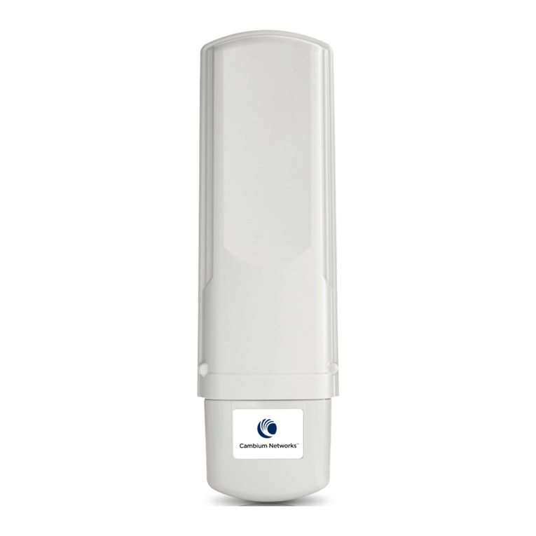
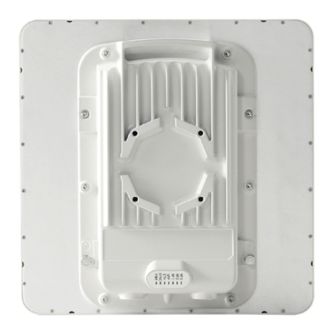
Cambium Networks PTP 670 Series User manual

QUICK START GUIDE
PTP 670 Series

PAGE 2
Content
ENGLISH (UK, IE, NO) .............................................................................................................. 8
NOTICES ...........................................................................................................................................................................9
About this Quick Start Guide........................................................................................................................................................................9
Intended use ..........................................................................................................................................................................................................9
Operation in the EU ...........................................................................................................................................................................................9
Simplified EU Declaration of Conformity................................................................................................................................................11
Professional installation ...................................................................................................................................................................................11
User documentation ..........................................................................................................................................................................................11
Waste Electrical and Electronic Equipment (WEEE).......................................................................................................................11
Safety.........................................................................................................................................................................................................................11
Equipment manufacturer...............................................................................................................................................................................13
TYPICAL INSTALLATIONS .....................................................................................................................................14
ODU VARIANTS AND MOUNTING BRACKET OPTIONS........................................................................15
INSTALLING THE ODU AND TOP LPU ............................................................................................................17
Attach ground cables to the ODU ............................................................................................................................................................17
Mount the ODU on the mast ........................................................................................................................................................................17
Mount the top LPU..........................................................................................................................................................................................20
Interconnect and ground the ODU and top LPU ............................................................................................................................20
Install external antennas for a Connectorized ODU ........................................................................................................................21
INSTALLING THE COPPER CAT5E ETHERNET INTERFACE ..............................................................23
Install the ODU to top LPU drop cable................................................................................................................................................. 23
Install the main drop cable.......................................................................................................................................................................... 25
Install the bottom LPU to PSU drop cable ..........................................................................................................................................27
Test resistance in the drop cable............................................................................................................................................................. 28
INSTALLING THE PSU ............................................................................................................................................ 30
Installing the AC Power Injector...............................................................................................................................................................30
Installing the AC+DC Enhanced Power Injector ..............................................................................................................................30
CONFIGURING THE ODU FOR OPERATION IN THE EU .......................................................................32
Generate a country-specific License Key............................................................................................................................................ 32
Configure the management PC................................................................................................................................................................ 32
Connect the ODU to the PC and powering up................................................................................................................................. 32
Logging into the web interface ................................................................................................................................................................ 32
Update the License Key and configure the ODU............................................................................................................................ 33
CZECH (CS)............................................................................................................................... 35
POZNÁMKY.................................................................................................................................................................. 36
O této píruce .................................................................................................................................................................................................. 36
Urení ..................................................................................................................................................................................................................... 36
Provoz v EU......................................................................................................................................................................................................... 36
Zjednodušené prohlášení o shod pro EU.......................................................................................................................................... 38
Odborná montáž .............................................................................................................................................................................................. 38
Uživatelská dokumentace............................................................................................................................................................................ 38
Odpadní elektrická a elektronická zaízení (OEEZ)....................................................................................................................... 38
Bezpenost.......................................................................................................................................................................................................... 38
Výrobce zaízení...............................................................................................................................................................................................40
TYPICKÉ ZP SOBY INSTALACE ........................................................................................................................41
VARIANTY VENKOVNÍ JEDNOTKY A DOSTUPNÉ MONTÁŽNÍ DRŽÁKY .................................. 42

PAGE 3
INSTALACE VENKOVNÍ JEDNOTKY A HORNÍ P EP OVÉ OCHRANY.................................... 44
Pipojení zemnicích kabel k venkovní jednotce.............................................................................................................................44
Upevnní venkovní jednotky na stožár ................................................................................................................................................44
Upevnní horní pepové ochrany........................................................................................................................................................ 47
Propojení a uzemnní venkovní jednotky a horní pepové ochrany ................................................................................ 47
Upevnní externích antén pro venkovní jednotku s konektorem...........................................................................................48
P IPOJENÍ M D NÉHO ETHERNETOVÉHO ROZHRANÍ CAT5E .................................................... 50
Pipojení pipojovacího kabelu od horní pepové ochrany k venkovní jednotce.......................................................50
Pipojení hlavního pipojovacího kabelu .............................................................................................................................................. 52
Upevnní pipojovacího kabelu mezi spodní pepovou ochranou a napájecím zdroje.......................................... 54
Zmení odporu pipojovacího kabelu.................................................................................................................................................. 55
INSTALACE NAPÁJECÍHO ZDROJE ................................................................................................................57
Pipojení stídavého napájecího injektoru........................................................................................................................................... 57
Pipojení rozšíeného stídavo-stejnosmrného napájecího injektoru................................................................................. 57
NASTAVENÍ VENKOVNÍ JEDNOTKY K PROVOZU V EU..................................................................... 59
Vygenerování licenního klíe pro konkrétní zemi......................................................................................................................... 59
Nastavení poítae používaného ke správ ...................................................................................................................................... 59
Pipojení venkovní jednotky k poítai a její zapnutí .................................................................................................................... 59
Pihlášení k webovému rozhraní .............................................................................................................................................................. 59
Aktualizace licenního klíe a nastavení venkovní jednotky.....................................................................................................60
FRENCH (FR)............................................................................................................................ 62
REMARQUES ............................................................................................................................................................... 63
À propos de ce guide de démarrage rapide ..................................................................................................................................... 63
Usage prévu........................................................................................................................................................................................................ 63
Exploitation dans l'UE.................................................................................................................................................................................... 63
Déclaration de conformité de l'UE simplifiée .................................................................................................................................... 65
Installation professionnelle.......................................................................................................................................................................... 65
Documentation de l'utilisateur .................................................................................................................................................................. 65
Mise au rebut des équipements électriques et électroniques (DEEE)................................................................................. 65
Sécurité.................................................................................................................................................................................................................. 65
Fabricant de l'équipement .......................................................................................................................................................................... 67
INSTALLATIONS TYPIQUES................................................................................................................................ 68
VARIANTES D'ODU ET OPTIONS DE MONTAGE SUR SUPPORT................................................... 69
INSTALLATION DE L'ODU ET DE LA LPU SUPÉRIEURE .......................................................................71
Connexion des câbles de masse à l'ODU ..............................................................................................................................................71
Montage de l'ODU sur le mât.......................................................................................................................................................................71
Montage de la LPU supérieure.................................................................................................................................................................. 74
Interconnexion et mise à la masse de l'ODU et de la LPU supérieure ................................................................................. 74
Installation des antenne externes pour une ODU connectée ................................................................................................... 75
INSTALLATION DE L'INTERFACE CUIVRE ETHERNET CAT. 5E ......................................................77
Installer le câble de liaison de l'ODU vers la LPU supérieure.....................................................................................................77
Installer le câble de liaison principal....................................................................................................................................................... 79
Installer le câble de liaison de la LPU inférieure à la PSU............................................................................................................. 81
Tester la résistance dans le câble de liaison ...................................................................................................................................... 82
INSTALLATION DE LA PSU ................................................................................................................................. 84
Installation de l'injecteur d'alimentation CA.......................................................................................................................................84
Installation de l'injecteur d'alimentation amélioré CA+CC .........................................................................................................84
CONFIGURATION DE L'ODU POUR EXPLOITATION DANS L'UE................................................... 86
Générer une clé de licence spécifique pour votre pays............................................................................................................... 86

PAGE 4
Configurer le PC de gestion ....................................................................................................................................................................... 86
Connecter l'ODU au PC et la mettre sous tension.......................................................................................................................... 86
Connexion à l'interface web ....................................................................................................................................................................... 87
Mettre à jour la clé de licence et configurer l'ODU ........................................................................................................................ 87
SPANISH (ES) ...........................................................................................................................89
AVISOS ...........................................................................................................................................................................90
Acerca de esta Guía de inicio rápido.....................................................................................................................................................90
Uso previsto ........................................................................................................................................................................................................90
Operación en la UE..........................................................................................................................................................................................90
Declaración de conformidad simplificada de la UE ....................................................................................................................... 92
Instalación profesional................................................................................................................................................................................... 92
Documentación del usuario........................................................................................................................................................................ 92
Directiva de Residuos de aparatos eléctricos y electrónicos (RAEE) ................................................................................. 92
Seguridad ............................................................................................................................................................................................................. 92
Fabricante del equipo....................................................................................................................................................................................94
INSTALACIONES TÍPICAS .................................................................................................................................... 95
VARIANTES DE ODU Y OPCIONES DE SOPORTE DE MONTAJE .................................................. 96
INSTALACIÓN DE LA ODU Y LA LPU SUPERIOR ................................................................................... 99
Fijación de cables de puesta a tierra a la ODU ................................................................................................................................99
Montaje de la ODU en el mástil................................................................................................................................................................. 99
Montaje de la LPU superior........................................................................................................................................................................102
Interconexión y puesta a tierra de la ODU y la LPU superior..................................................................................................102
Instalación de antenas externas para una ODU conectorizada............................................................................................. 103
INSTALACIÓN DE LA INTERFAZ DE COBRE ETHERNET CAT5E..................................................105
Instalación del cable de bajada de la ODU a la LPU superior................................................................................................. 105
Instalación del cable de bajada principal............................................................................................................................................107
Instalación del cable de bajada de la LPU inferior a la fuente de alimentación............................................................ 109
Comprobación de resistencia en el cable de bajada...................................................................................................................... 111
INSTALACIÓN DE LA FUENTE DE ALIMENTACIÓN.............................................................................. 112
Instalación del inyector de alimentación de CA .............................................................................................................................. 112
Instalación del inyector de alimentación reforzado de CA+CC............................................................................................... 112
CONFIGURACIÓN DE LA ODU PARA OPERACIÓN EN LA UE ........................................................114
Generación de una clave de licencia específica del país.............................................................................................................114
Configuración del PC de administración .............................................................................................................................................114
Conexión de la ODU al PC y encendido...............................................................................................................................................114
Inicio de sesión en la interfaz web .......................................................................................................................................................... 115
Actualización de la clave de licencia y configuración de la ODU........................................................................................... 115
ITALIAN (IT)..............................................................................................................................117
AVVISI ............................................................................................................................................................................. 118
Informazioni su questa Guida introduttiva ......................................................................................................................................... 118
Uso previsto ........................................................................................................................................................................................................118
Funzionamento nell’UE .................................................................................................................................................................................118
Dichiarazione di conformità UE semplificata ...................................................................................................................................120
Installazione professionale .........................................................................................................................................................................120
Documentazione utente ..............................................................................................................................................................................120
Direttiva sui rifiuti di apparecchiature elettriche ed elettroniche (RAEE) ........................................................................120
Sicurezza .............................................................................................................................................................................................................120
Produttore delle apparecchiature ..........................................................................................................................................................122
INSTALLAZIONI TIPICHE ..................................................................................................................................... 123

PAGE 5
VARIANTI ODU E OPZIONI DI MONTAGGIO CON TRAVERSINO..................................................124
INSTALLAZIONE DI ODU E LPU SUPERIORE...........................................................................................126
Collegare i cavi di terra all’ODU...............................................................................................................................................................126
Montare l’ODU sull’albero ...........................................................................................................................................................................126
Montare la LPU superiore ...........................................................................................................................................................................129
Interconnettere e mettere a terra l’ODU e la LPU superiore....................................................................................................129
Installare antenne esterne per un’ODU connettorizzata ........................................................................................................... 130
INSTALLAZIONE DELL’INTERFACCIA ETHERNET CAT5E IN RAME........................................... 132
Installare l’ODU sul cavo di discesa della LPU superiore............................................................................................................132
Installare il cavo di discesa principale ..................................................................................................................................................134
Installare il cavo di discesa dalla LPU inferiore alla PSU.............................................................................................................136
Verificare la resistenza nel cavo di discesa .......................................................................................................................................138
INSTALLAZIONE DELLA PSU............................................................................................................................139
Installazione dell’iniettore di alimentazione CA...............................................................................................................................139
Installazione dell’iniettore di alimentazione CA+CC .....................................................................................................................139
CONFIGURAZIONE DELL’ODU PER IL FUNZIONAMENTO NELL’UE............................................ 141
Generare un codice di licenza specifico per Paese........................................................................................................................141
Configurare il PC di gestione .....................................................................................................................................................................141
Collegare l’ODU al PC e accenderla .......................................................................................................................................................141
Accesso all’interfaccia Web........................................................................................................................................................................141
Aggiornare il codice di licenza e configurare l’ODU.....................................................................................................................142
POLISH (PL) ............................................................................................................................ 144
INFORMACJE .............................................................................................................................................................145
Informacje o tym podrczniku wprowadzajcym .........................................................................................................................145
Przeznaczenie:..................................................................................................................................................................................................145
Stosowanie na terenie UE...........................................................................................................................................................................145
Uproszczona deklaracja zgodnoci UE ...............................................................................................................................................147
Profesjonalna instalacja................................................................................................................................................................................147
User documentation ......................................................................................................................................................................................147
Dyrektywa o zuytym sprzcie elektrycznym i elektronicznym (WEEE):........................................................................147
Bezpiecze stwo...............................................................................................................................................................................................148
Producent urzdzenia.................................................................................................................................................................................. 150
TYPOWA INSTALACJA ......................................................................................................................................... 151
WARIANTY ODU I OPCJE KLAMRY MONTA OWEJ ........................................................................... 152
MONTA ODU I GÓRNEGO LPU......................................................................................................................154
Podłczanie kabli dosyłowych do ODU..............................................................................................................................................154
Monta ODU na maszcie.............................................................................................................................................................................154
Monta górnych LPU.....................................................................................................................................................................................157
Połczenie i uziemienie ODU oraz górnego LPU...........................................................................................................................157
Monta zewntrznych anten do ODU ze złczem anteny zewntrznej ............................................................................158
MONTA ZŁ CZA KABLA MIEDZIANEGO CAT5E ETHERNET......................................................160
Monta kabla dołczeniowego midzy ODU a górnym LPU.................................................................................................. 160
Monta głównego kabla dołczeniowego.........................................................................................................................................162
Monta kabla dołczeniowego midzy dolnym LPU a zasilaczem ......................................................................................164
Testowanie rezystancji w kablu dołczeniowym...........................................................................................................................166
MONTA ZASILACZA............................................................................................................................................ 167
Monta zasilacza (AC Power Injector).................................................................................................................................................167
Monta zasilacza AC+DC Enhanced Power Injector ....................................................................................................................167
CONFIGURING THE ODU FOR OPERATION IN THE EU .....................................................................169

PAGE 6
Generate a country-specific License Key...........................................................................................................................................169
Konfiguracja komputera do zarzdzania............................................................................................................................................169
Podłczanie ODU do komputera i włczanie urzdzenia..........................................................................................................169
Logowanie do interfejsu w przegldarce internetowej ..............................................................................................................170
Aktualizacja klucza licencyjnego i konfiguracja ODU. .................................................................................................................170
TURKISH (TR)..........................................................................................................................172
UYARILAR.................................................................................................................................................................... 173
Bu HızlıBalangıç Kılavuzu Hakkında...................................................................................................................................................173
Kullanım amacı..................................................................................................................................................................................................173
AB'de Çalıtırma ..............................................................................................................................................................................................173
Basitletirilmi AB Uygunluk Beyanı......................................................................................................................................................175
Profesyonel kurulum......................................................................................................................................................................................175
Kullanıcıbelgeleri ............................................................................................................................................................................................175
Atık Elektrikli ve Elektronik Ekipmanlar (WEEE)............................................................................................................................175
Güvenlik................................................................................................................................................................................................................175
Ekipman üreticisi ............................................................................................................................................................................................. 177
TIPIK KURULUMLAR............................................................................................................................................... 178
DI MEKAN ÜNITESI ÇE ITLERI VE MONTAJ DIRSE I SEÇENEKLERI ......................................179
DI MEKAN ÜNITESI (ODU) VE EN ÜST PARATONER ÜNITESI (LPU) KURULUMU ............ 181
Topraklama kablolarınıDı Mekan Ünitesine takın .........................................................................................................................181
Dı Mekan Ünitesi dire e monte etme ..................................................................................................................................................181
En Üstteki Paratoner Ünitesini Monte Etme......................................................................................................................................184
Dı Mekan Ünitesi ve Paratoner Ünitesini birbirine ba lama ve topraklama ...................................................................184
Konektörlü Dı Mekan Ünitesi için harici antenleri kurma..........................................................................................................185
BAKIR CAT5E ETHERNET ARAYÜZÜNÜN KURULMASI..................................................................... 187
Dı Mekan Ünitesi'ni en üstteki Paratoner Ünitesi saplama kablosuna takma ................................................................187
Ana saplama kablosunu takma................................................................................................................................................................189
En alttaki Paratoner Ünitesini Güç Kayna ıÜnitesi saplama kablosuna takma ..............................................................191
Saplama kablosundaki direnci test etme............................................................................................................................................192
GÜÇ KAYNA I ÜNITESINI KURMA .................................................................................................................194
AC Güç Enjektörünü Kurma ......................................................................................................................................................................194
AC+DC Gelimi Güç Enjektörünü Kurma..........................................................................................................................................194
DI MEKAN ÜNITESINI AB'DE ÇALI TIRMA IÇIN YAPILANDIRMA...............................................196
Ülkeye özel Lisans Anahtarıoluturma................................................................................................................................................196
Yönetim bilgisayarınıyapılandırma........................................................................................................................................................196
Dı Mekan Ünitesini bilgisayara ba lama ve güç verme.............................................................................................................196
Web arayüzüne giri......................................................................................................................................................................................197
Lisans Anahtarınıgüncelleme ve Dı Mekan Ünitesini yapılandırma....................................................................................197
HUNGARIAN (HU) ................................................................................................................. 199
EL ZETES INFORMÁCIÓK ............................................................................................................................... 200
A jelen rövid útmutatóról..........................................................................................................................................................................200
Rendeltetésszer használat.....................................................................................................................................................................200
EU-beli üzemeltetés.....................................................................................................................................................................................200
Egyszersített EU-s megfelel ségi nyilatkozat............................................................................................................................. 202
Szakszer telepítés....................................................................................................................................................................................... 202
Felhasználói dokumentáció ..................................................................................................................................................................... 202
Az elektromos és elektronikus berendezések hulladékai (WEEE)...................................................................................... 202
Személybiztonság......................................................................................................................................................................................... 203
Berendezésgyártó......................................................................................................................................................................................... 205

PAGE 7
JELLEMZ ELRENDEZÉSEK............................................................................................................................ 206
A KÜLTÉRI EGYSÉG VÁLTOZATAI ÉS A RÖGZÍT ELEM-VÁLASZTÉK ...................................207
A KÜLTÉRI EGYSÉG ÉS A FELS VILLÁMVÉDELMI EGYSÉG TELEPÍTÉSE........................... 209
Földel kábelek csatlakoztatása a kültéri egységhez ................................................................................................................. 209
A kültéri egység felszerelése az antennaárbócra ........................................................................................................................ 209
A fels villámvédelmi egység felszerelése.........................................................................................................................................212
A kültéri egység és a fels villámvédelmi egység egymáshoz való csatlakoztatása és földelése....................... 212
Küls antennák telepítése csatlakozóval ellátott kültéri egységhez....................................................................................213
A RÉZ CAT5E ETHERNET INTERFÉSZ TELEPÍTÉSE............................................................................. 215
A kültéri egység és a fels LPU közötti beköt kábel beszerelése........................................................................................215
A f beköt kábel beszerelése .................................................................................................................................................................. 217
Az alsó LPU és a tápegység közötti beköt kábel beszerelése ..............................................................................................219
A beköt kábelben lév ellenállás tesztelése...............................................................................................................................221
A TÁPEGYSÉG TELEPÍTÉSE.............................................................................................................................. 222
Az AC Power Injector telepítése............................................................................................................................................................222
Az AC+DC Enhanced Power Injector telepítése............................................................................................................................222
A KÜLTÉRI EGYSÉG KONFIGURÁLÁSA EU-BELI ÜZEMELTETÉSRE .........................................224
Országspecifikus licenckulcs generálása...........................................................................................................................................224
A kezelési PC számítógép konfigurálása...........................................................................................................................................224
A kültéri egység csatlakoztatása a PC-hez és áram alá helyezés ........................................................................................224
Bejelentkezés a webes felületre .............................................................................................................................................................224
A licenckulcs frissítése a kültéri egység konfigurálása...............................................................................................................225

PTP 670 QUICK START GUIDE
PAGE 8
English (UK, IE, NO)
Accuracy
While reasonable efforts have been made to assure the accuracy of this document, Cambium Networks assumes
no liability resulting from any inaccuracies or omissions in this document, or from use of the information
obtained herein. Cambium Networks reserves the right to make changes to any products described herein to
improve reliability, function, or design, and reserves the right to revise this document and to make changes from
time to time in content hereof with no obligation to notify any person of revisions or changes. Cambium
Networks does not assume any liability arising out of the application or use of any product, software, or circuit
described herein; neither does it convey license under its patent rights or the rights of others. It is possible that
this publication may contain references to, or information about Cambium Networks products (machines and
programs), programming, or services that are not announced in your country. Such references or information
must not be construed to mean that Cambium Networks intends to announce such Cambium Networks products,
programming, or services in your country.
Copyrights
This document, Cambium Networks products, and 3rd Party software products described in this document may
include or describe copyrighted Cambium Networks and other 3rd Party supplied computer programs stored in
semiconductor memories or other media. Laws in the United States and other countries preserve for Cambium
Networks, its licensors, and other 3rd Party supplied software certain exclusive rights for copyrighted material,
including the exclusive right to copy, reproduce in any form, distribute and make derivative works of the
copyrighted material. Accordingly, any copyrighted material of Cambium Networks, its licensors, or the 3rd Party
software supplied material contained in the Cambium Networks products described in this document may not be
copied, reproduced, reverse engineered, distributed, merged or modified in any manner without the express
written permission of Cambium Networks. Furthermore, the purchase of Cambium Networks products shall not
be deemed to grant either directly or by implication, estoppel, or otherwise, any license under the copyrights,
patents or patent applications of Cambium Networks or other 3rd Party supplied software, except for the normal
non-exclusive, royalty free license to use that arises by operation of law in the sale of a product.
Restrictions
Software and documentation are copyrighted materials. Making unauthorized copies is prohibited by law. No
part of the software or documentation may be reproduced, transmitted, transcribed, stored in a retrieval system,
or translated into any language or computer language, in any form or by any means, without prior written
permission of Cambium Networks.
License Agreements
The software described in this document is the property of Cambium Networks and its licensors. It is furnished
by express license agreement only and may be used only in accordance with the terms of such an agreement.
High Risk Materials
Cambium and its supplier(s) specifically disclaim any express or implied warranty of fitness for any high risk
activities or uses of its products including, but not limited to, the operation of nuclear facilities, aircraft
navigation or aircraft communication systems, air traffic control, life support, or weapons systems (“High Risk
Use”). Any High Risk is unauthorized, is made at your own risk and you shall be responsible for any and all
losses, damage or claims arising out of any High Risk Use.

PTP 670 QUICK START GUIDE
PAGE 9
Notices
About this Quick Start Guide
This Quick Start Guide describes how to install the site equipment for PTP 670 Series links. Users of this guide
must follow good practice for outdoor radio installations.
In more advanced configurations, there may be one or two additional Ethernet interfaces connected to the ODU:
one to the SFP port (copper or optical) and one to the AUX port. For details of these configurations, refer to the
PTP 670 Series User Guide.
This Quick Start Guide describes how to deploy PTP 670 in the following countries:
Ireland
Norway
United Kingdom (UK)
PTP 670 Quick Start Guides are available for other EU member states. Please visit:
http://www.cambiumnetworks.com/guides
Intended use
The Cambium Networks PTP 670 series of radio products support data transmission over Point to Point (PTP)
microwave links. This radio equipment is intended for professional applications for fixed outdoor installations
only. These radios are available with an integrated antenna or as a unit for connection to an external antenna.
Operation in the EU
Frequency Bands, Maximum Operating Power, Safe Distance
The PTP 670 series products operate in the following frequency bands up to the maximum power shown:
Operating
Frequency Band
EU Standard Maximum
Power Limit
(EIRP)
Permitted Usage Minimum
Safe Distance
4940 – 4990 MHz EN 302 625 8 watts/39 dBm Norway: Broadband Disaster
Relief
0 cm
5150 – 5250 MHz EN 302 625 8 watts/39 dBm Norway: Broadband Disaster
Relief
0 cm
5470 – 5600 MHz
5650 – 5725 MHz
EN 301 893 1 watt/30 dBm UK, Ireland, Norway: Unlicensed. 0 cm
5725 – 5875 MHz EN 302 502 2 watts/33 dBm Ireland: light licensing applies.
Obtain a license from your
government web-site.
0 cm
5725 – 5850 MHz EN 302 502 4 watts/36 dBm UK: light licensing applies. Obtain
a license from your government
web-site.
0 cm
5725 – 5795 MHz,
5815 – 5850 MHz
NCOM Reg. 628
EN 302 502
200 watts/53
dBm
Norway: Unlicensed 1.1 m
Restrictions and requirements for authorization for use
This equipment is for outdoor use only.

PTP 670 QUICK START GUIDE
PAGE 10
The Cambium PTP 670 series of products can be configured to operate in either licensed or unlicensed
frequency bands subject to frequency planning within individual countries. Operators and end users must ensure
that the equipment is installed and operated in accordance with the regulations applicable to the country of
operation and obtain any necessary licenses or permits.
Antennas for connectorized units
PTP 670 Connectorised ODUs are designed to connect to a dual polarized antenna, using vertical and horizontal
polarization. The radios have been tested for EU regulatory compliance using the antenna types listed below.
The maximum gain of each antenna type is shown. Antennas of equivalent gain or lower and of the same
antenna type may be used. Do not use an antenna with higher gain. To reduce potential radio interference to
other users, the antenna type and its gain must be so chosen that the equivalent isotropic radiated power (EIRP)
is not more than that necessary for successful communication.
Antenna Type Manufacturer’s Antenna Gain (dBi)
4.9 GHz Band, 5.1 GHz Band 5.4 GHz Band 5.8 GHz Band
6 foot (1.8 m) Parabolic Dish 36.0 Not Supported 38.1
4 foot (1.2 m) Parabolic Dish 32.6 34.9 35.3
Flat Plate 23.0 23.0 23.0
Sectorised 17.0 17.0 17.0
Omnidirectional 13.0 13.0 13.0
Recommended parabolic dish antennas
The following parabolic dish antennas are suitable for use with PTP 670 Connectorized ODUs, subject to the
maximum antenna gain shown above.
Cambium part
number
Description
RDH4503B 5.25-5.85GHz 2-ft (0.6m), 29.0 dBi, Dual-polarization, H-Pol & V-Pol, with fine adjustments
RDH4504B 5.25-5.85GHz 3-ft (0.9m), 32.5 dBi, Dual-polarization, H-Pol & V-Pol
RDH4505B 5.25-5.85GHz 4-ft (1.2m), 34.9 dBi, Dual-polarization, H-Pol & V-Pol
RDH4506B 5.25-5.85GHz 6-ft (1.8m), 37.9 dBi, Dual-polarization, H-Pol & V-Pol
RDH4508B 5.25-5.85GHz 2-ft (0.6m), 28.8 dBi, High Performance Dual-polarization
RDH4509B 5.25-5.85GHz 3-ft (0.9m), 32.3 dBi, High Performance Dual-polarization
RDH4510B 5.25-5.85GHz 4-ft (1.2m), 34.7 dBi, High Performance Dual-polarization
RDH4511B 5.25-5.85GHz 6-ft (1.8m), 37.7 dBi, High Performance Dual-polarization
Configuration of the ODU
Please observe the following important instructions during installation. This will set the equipment in compliance
with national regulatory regulations.
Ensure that the ODU has the latest firmware version installed. The firmware is available from the Cambium
Support Centre web site, see link below.
During equipment set-up, verify that the ODU is the EU regional variant. Use the Cambium Support Center
to generate a country-specific License Key for the country where the product is being operated. Install the
License Key in the ODU. The License Key will unlock additional regulatory bands that are allowed in the
country of operation.

PTP 670 QUICK START GUIDE
PAGE 11
For connectorized units, enter the antenna gain and cable loss into the Antenna Gain and Cable Loss
attributes on the System Configuration page of the web-based interface.
Simplified EU Declaration of Conformity
Hereby, the manufacturer Cambium Networks Ltd, declares that the radio equipment types 5 GHz PTP 670
Connectorised ODU and 5 GHz PTP 670 Integrated ODU are in compliance with Directive 2014/53/EU. The full
text of the EU declaration of conformity is available at:
http://www.cambiumnetworks.com/support/compliance/
Professional installation
Installation and operation of this product is complex. Please follow the instructions in this leaflet. Ensure that
operation complies with the regulations of the country where the product is installed. Ensure that installers have
the appropriate skills, knowledge and experience to perform the installation task including:
Familiarity with current applicable national regulations including radio regulations, electrical installation
regulations, surge protection regulations and ‘working at heights’ regulations;
Installation in accordance with Cambium Networks instructions;
Confirming that the equipment settings are compliant with national or regional regulations.
User documentation
For full PTP 670 installation planning instructions and a list of components, download the
PTP 670 Series User
Guide
from:
http://support.cambiumnetworks.com/files/ptp670
Waste Electrical and Electronic Equipment (WEEE)
Please do not dispose of Electronic and Electric Equipment or Electronic and Electric
Accessories with your household waste. In some countries or regions, collection systems have
been set up to handle waste of electrical and electronic equipment. In European Union
countries, please contact your local equipment supplier representative or Cambium Networks
Support Centre for information about the waste collection system in your country.
For instructions on waste disposal of used products, refer to:
http://www.cambiumnetworks.com/support/weee-compliance
Safety
Warning To prevent loss of life or physical injury, observe the safety guidelines below. In no
event shall Cambium Networks be liable for any injury or damage caused during the
installation of the Cambium PTP 670. Ensure that only qualified personnel install a PTP 670
link.
Power lines
Exercise extreme care when working near power lines.
Working at heights
Exercise extreme care when working at heights.

PTP 670 QUICK START GUIDE
PAGE 12
PSU
Always use the AC Power Injector or AC+DC Enhanced Power Injector to power the ODU. Failure to use a
Cambium supplied PSU could result in equipment damage and will invalidate the safety certification and may
cause a safety hazard.
Grounding and protective earth
The Outdoor Unit (ODU) must be properly grounded to protect against lightning. It is the user’s responsibility to
install the equipment in accordance with national regulations. In the USA follow the requirements of the National
Electrical code NFPA 70-2005 and 780-2004
Installation of Lightning Protection Systems
. In Canada, follow
Section 54 of the
Canadian Electrical Code
. These codes describe correct installation procedures for grounding
the outdoor unit, mast, lead in wire and discharge unit, size of grounding conductors and connection
requirements for grounding electrodes. Other regulations may apply in different countries and therefore it is
recommended that installation of the outdoor unit be contracted to a professional installer.
DC supply
To power the ODU from a DC supply, use the AC+DC enhanced power injector (PSU) (Cambium part number
C000065L002C). Ensure that the DC power supply meets the requirements specified in the
PTP 670 Series User
Guide.
Powering down before servicing
Before servicing PTP 670 equipment, always switch off the power supply and unplug it from the PSU.
Do not disconnect the RJ45 drop cable connectors from the ODU while the PSU is connected to the power
supply. Always remove the AC or DC input power from the PSU.
Primary disconnect device
The main power supply is the primary disconnect device. The AC-DC enhanced power injector is fused on the DC
input. Some installations will also require an additional circuit breaker or isolation switch to be fitted in the DC
supply.
External cables
Safety may be compromised if outdoor rated cables are not used for connections that will be exposed to the
outdoor environment. For outdoor copper Cat5e Ethernet interfaces, always use Cat5e cable that is gel-filled
and shielded with copper-plated steel. Alternative types of drop cable are not supported by Cambium Networks
for use with PTP 670.
Always use a qualified electrician to install AC cabling.
Drop cable tester
A drop cable tester must NEVER be used at the ODU end connected to the power supply from the PSU. It must
only be used at the bottom of the mast with a multimeter. This is because the PSU voltage exceeds the limit
allowed in some countries for safe handling in wet conditions and therefore may create a safety hazard.
RF exposure near the antenna
Strong radio frequency (RF) fields will be present close to the antenna when the transmitter is on. Always turn
off the power to the ODU before undertaking maintenance activities in front of the antenna.
Minimum separation distances
Ensure that personnel are not exposed to unsafe levels of RF energy. The units start to radiate RF energy as
soon as they are powered up. Never work in front of the antenna when the ODU is powered. Install the ODUs so
as to provide and maintain the minimum separation distances from all persons.
Grounding and lightning protection requirements

PTP 670 QUICK START GUIDE
PAGE 13
Ensure that the installation meets the requirements defined in the
PTP 670 Series User Guide
.
Grounding cable installation methods
To provide effective protection against lightning induced surges, observe these requirements:
Grounding conductor runs must be as short, straight and smooth as possible, with bends and curves kept to
a minimum.
Grounding cables must not be installed with drip loops.
All bends must have a minimum radius of 203 mm (8 in) and a minimum angle of 90°. A diagonal run is
preferable to a bend, even though it does not follow the contour or run parallel to the supporting structure.
All bends, curves and connections must be routed towards the grounding electrode system, ground rod, or
ground bar.
Grounding conductors must be securely fastened.
Braided grounding conductors must not be used.
Approved bonding techniques must be used for the connection of dissimilar metals.
Siting ODUs and antennas
ODUs and external antennas are not designed to survive direct lightning strike. For this reason they must be
installed in Zone B as defined in
PTP 670 Series User Guide
. Mounting in Zone A may put equipment, structures
and life at risk.
Wind survival speeds
Ensure that the ODU and the structure to which it is mounted can withstand the maximum wind speeds at a
proposed site.
Surface temperature
The ODU enclosure may be hot to the touch when in operation.
Equipment manufacturer
Cambium Networks Ltd, Unit B2 Linhay Business Park, Eastern Road, Ashburton, Devon, TQ13 7UP, United
Kingdom.

PTP 670 QUICK START GUIDE
PAGE 14
Typical installations
A PTP 670 site typically consists of a high supporting structure such as a mast, tower or building for the outdoor
equipment (ODU and optional external antenna); and an equipment building or moisture-proof enclosure for the
indoor equipment (PSU), as shown here in a typical mast or tower installation:
Note These instructions assume that LPUs are being installed from the LPU and grounding kit
(Cambium part number C000065L007A). If the installation does not require LPUs, adapt these
instructions as appropriate.
If LPUs are being installed, only use the five black-capped EMC cable glands supplied in the
LPU and grounding kit. The silver-capped cable glands supplied in the ODU kits must only be
used in PTP 670 installations which do not require LPUs.
Building
entry
Groundring
PSU
Firstpointofcontactbetween
dro p cablea nd to wer
ODU
Network
equipment
BottomLPU
TopLPU
Intermediategroundcable(s)as
required
AC/DCSupply
Equipmentbuildingorcabinet
Towergroundbar
PTP670Groundcables
PoweroverEthernetCAT5ecable(gel‐filled
shieldedwithcopper‐platedsteel)
Sitegroundingsystem
NetworkCAT5ecable

PTP 670 QUICK START GUIDE
PAGE 15
ODU variants and mounting bracket options
ODU variants
The PTP 670 ODU is supplied in two platform variants.
The PTP 670 Integrated ODU is attached to a 23 dBi flat plate antenna and is intended for medium to long-range
difficult links and traditional backhaul requirements where high capacity and high link budget are required. The
integrated antenna offers a convenient and easily-deployed solution where the additional gain of external
antennas is not needed.
Integrated ODU (4.8 to 5.9 GHz)
Integrated ODU (4.9 to 6.05 GHz)

PTP 670 QUICK START GUIDE
PAGE 16
The PTP 670 Connectorized ODU is intended to work with separately mounted external antennas. External
antennas generally have higher gains than the integrated antennas, allowing the PTP 670 to cope with more
difficult radio conditions.
Mounting bracket options
The PTP 670 series supports three mounting bracket options. Select the optimum mounting bracket
arrangement based on the pole diameter and the ODU variant:
Bracket Pole diameter ODU variants Bracket part number
Tilt Bracket Assembly 40 mm to 77 mm (1.6
inches to 3.0 inches)
PTP 670 Integrated PTP
670 Connectorized
N000045L002A
Tilt Bracket Assembly
with compression straps
90 mm to 230 mm (3.6
inches to 9.0 inches)
PTP 670 Integrated PTP
670 Connectorized
N000045L002A + third-
party band clamps
Mounting Bracket
(Integrated)
40 mm to 82 mm (1.6
inches to 3.2 inches)
PTP 670 Integrated N000065L031A
Note The Tilt Bracket Assembly is included as part of the PTP 670 Integrated and
Connectorized Kits. If required, order the Mounting Bracket (Integrated) separately.
Note The Tilt Bracket Assembly allows for elevation angle adjustment for the Integrated ODU
between –17° and +26°. The Mounting Bracket (Integrated) allows for elevation angle
adjustment between –26° and +41°.

PTP 670 QUICK START GUIDE
PAGE 17
Installing the ODU and top LPU
Attach ground cables to the ODU
Fasten one ground cable to each ODU grounding point using the M6 (small) lugs: one is for the top LPU (M6
lug at other end) and the other is for the tower or building (M10 lug at other end). It does not matter which
cable goes on which ODU grounding point.
Tighten both ODU grounding bolts to a torque of 5.0 Nm (3.7 lb ft).
12
Mount the ODU on the mast
Select the most appropriate bracket mounting arrangement from the options listed in Mounting bracket options
on page 16. Refer to individual procedures below for each of the options:
Tilt Bracket Assembly on page 17
Tilt Bracket Assembly with band clamps on page 18
Mounting bracket (Integrated) on page 19
The mounting procedures can be adapted to attach the ODU to a suitable horizontal pole, but the adjustment of
azimuth angle is necessarily limited compared with an installation on a vertical pole.
Tilt Bracket Assembly
Fix the mounting plate of the Tilt Bracket to the back of the ODU using four of the short bolts, ensuring that
the arrow in the plate points towards the top of the ODU. Tighten the four bolts to a torque setting of 5.0
Nm (3.7 lb ft) using a 13 mm spanner or socket.
Fit the two long bolts through the bracket body so that the bolt heads engage in the slots as shown. Fit two
of the short bolts into the side of the bracket body but do not tighten.
Thread two of the nuts to the long bolts and tighten against the bracket body using a 13 mm spanner. Fit
the bracket strap and thread the remaining nuts onto the long bolts.
Fix the assembled bracket body to the pole, adjust the azimuth angle, and tighten the nuts to a torque
setting of 10.0 Nm (7.4 lb ft) using a 13 mm spanner, ensuring that the arrow in the body is pointing
upwards.
Hoist the ODU to the mounting position. Fit the mounting plate to the bracket body by positioning the
open-ended slots over the short bolts. Insert the remaining short bolts through the longer curved slots into
the threaded holes in the bracket body. Adjust the elevation angle, and tighten the bolts to a torque setting
of 8.0 Nm (5.9 lb ft) using a 13 mm spanner or socket.

PTP 670 QUICK START GUIDE
PAGE 18
Tilt Bracket Assembly with band clamps
Follow Step 1 for the Tilt Bracket Assembly procedure above.
Feed the band clamps (not supplied by Cambium) through the slots in the bracket body. Secure the bracket
body to the pole using band clamps, ensuring that the arrow in the body is pointing upwards. Adjust the
azimuth angle, and tighten the band clamps to a torque setting of 6.0 Nm (4.5 lb ft).
Hoist the ODU to the mounting position. Fix the mounting plate to the bracket body with four of the short
bolts, using a 13 mm spanner or socket. Adjust the elevation angle, and tighten the bolts to a torque setting
of 8.0 Nm (5.9 lb ft).

PTP 670 QUICK START GUIDE
PAGE 19
Mounting bracket (Integrated)
Fix the mounting plate to the back of the ODU using the four bolts, and spring and plain washers provided.
Ensure that the spring washer is between the bolt head and the plain washer. Tighten the bolts to a torque
setting of 5.0 Nm (3.7 lb ft).
Attach the bracket body to the mounting plate using the M8 bolt, spring and plain washers. Ensure that the
spring washer is between the bolt head and the plain washer
Hoist the ODU to the mounting position.
Attach the bracket body to the pole using the bracket clamp, M8 bolts, and spring and plain washers.
Ensure that the spring washer is between the bolt head and the plain washer. For back-to-back mounting,
use the LPU in place of the clamp.
Adjust the elevation and azimuth to achieve visual alignment. Tighten all three bracket bolts to a torque of
8.0 Nm (6.0 lb ft).
Attention Do not reverse the bracket clamp, as shown in 7 above as this arrangement may lead
to failure of the assembly. Do not over-tighten the bolts as this may lead to failure of the
assembly.

PTP 670 QUICK START GUIDE
PAGE 20
Mount the top LPU
For separate LPU mounting, use the U bolt bracket from the LPU kit to mount the top LPU on the pole below the
ODU. Tighten to a torque setting of 7.0 Nm (5.2 lb ft):
Interconnect and ground the ODU and top LPU
Drop cable to
bottom LPU
Grounding
system
Mounting pole
LPU mounted
back-to-back
with the ODU
ODU to top
LPU ground
cable
Drop cable
grounding
point
ODU t o
grounding
system
ODU t o top
LPU dr op
cable
ODU
ODU mounted
on pole with
bracket
Top LPU
mounted on
pole with U-bolt
fr om LPU kit
Drop cable
grounding
point
ODU to t op
LPU ground
cable
Mounting pole
ODU t o
grounding
system
ODU t o top
LPU dr op
cable
Op tion 1: back-to-back Option 2: separate
Drop cable to
bottom LPU
Grounding
system
ODU
Grounding
points at
opposite
sides of
ODU
Grounding
points at
opposite
sides of
ODU
Other manuals for PTP 670 Series
1
Table of contents
Languages:
Other Cambium Networks Network Router manuals

Cambium Networks
Cambium Networks PTP 820 Series User manual

Cambium Networks
Cambium Networks PTP 820C User manual

Cambium Networks
Cambium Networks PTP 250 User manual

Cambium Networks
Cambium Networks PTP 670 Series User manual

Cambium Networks
Cambium Networks PTP 550 Series User manual

Cambium Networks
Cambium Networks PTP 820C User manual

Cambium Networks
Cambium Networks cnPilot Home R200 Series User manual

Cambium Networks
Cambium Networks PTP 650 User manual

Cambium Networks
Cambium Networks PTP 450 Series User manual

Cambium Networks
Cambium Networks PTP 820C HP User manual