Cambo Wide RS 1600 Series User manual

REV 10-2016
CAMBO
Wide RS 1600 series
E
INSTRUCTION
MANUAL

2

3
Thank you for purchasing a Cambo product.
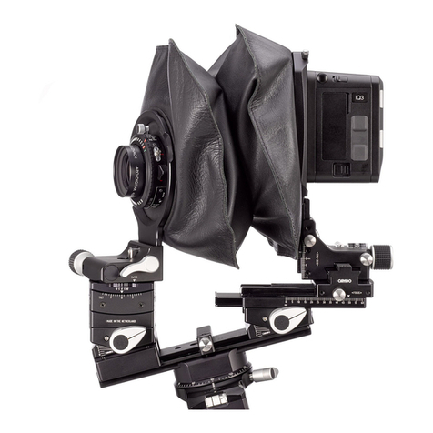
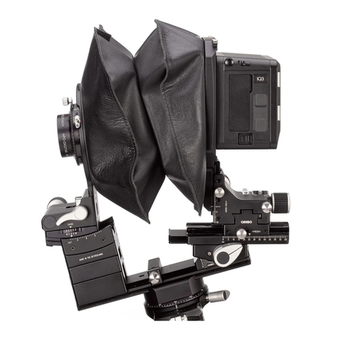
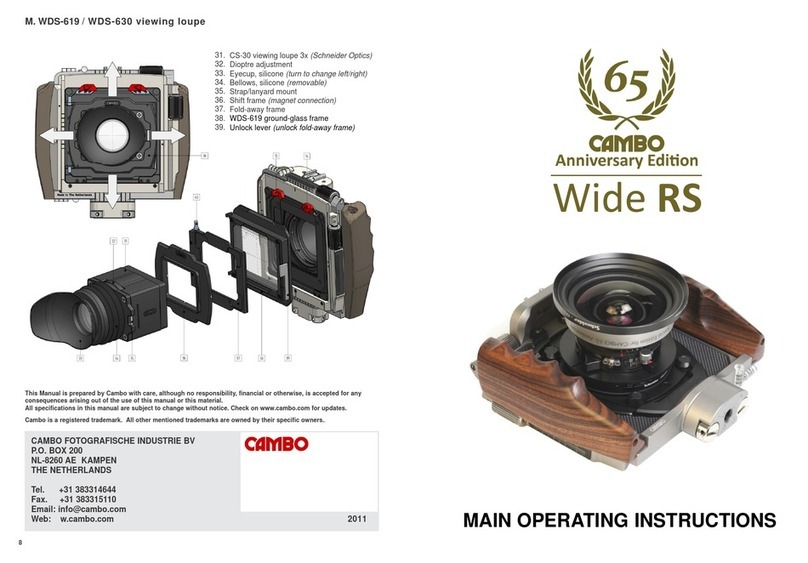
The Wide RS is a compact medium format system camera
featuring lateral and vertical shift of the rear standard. The
precision rear shift/rise and fall control is ideal for architecture
and landscape photography. It enables the photographer the use
perspective control, image displacement and high quality
panoramic stitching. A unique feature of the WRS 1600 is its
ability to rotate the full camera/lens/back assembly in the tripod
mount between landscape and portrait mode within seconds.
Key Features:
• Small size 180 x 160mm (W x H)
• Lightweight only 0.92 kgs (excl. lens)
• High grade aluminum camera body and shift plates
• Horizontal shift 40mm (20mm left/20mm right)
• Vertical shift 40mm (20mm / 20mm)
• Stitching possibilities (2 way / 4 way)
• Accelerated precision spindle gear drive
• Millimeter movement indicator
• Movement indicators on rear sides
• Sensible click indication at 5, 10 and 15mm
• Compatible with WDS and Wide Compact
• Integrated hand grip
• Removable cable release (included)
• Removable Arca plate
• 3 integrated spirit levels
• Accessory mount for 2 point fixed accessories
• LED light (included)
• Compact soft case (included)
• Broad range of optics
• Retrofitting of user lenses offered

4
A. MOUNT NG THE LENS PANEL
The Wide RS system is compatible with the Cambo WDS/WTS
lens panels.
1. Open both lens panel locks
2. Slide the bottom of the lens plate into the lens panel slot
3. Tilt the lens panel flat to the camera body
4. lock both lens panel lock

5
B. MOUNT NG AN NTERFACE ADAPTER
The Wide RS system is compatible with the Cambo SLW interface
plates. The available interface (adapter) plates are:
Interface plate Compatible mount
SLW 80 Hasselblad® V
SLW 81 Leaf® AFi, Sinar® HY6
SLW 83 PhaseOne® (including IQ3 series)
SLW 88 (discontinued) PhaseOne®, Mamiya® 645 AFd
SLW 87 Contax® 645
SLW 89 Hasselblad® H
WRS 1068 (SLW mount) Mamiya® RB roll film holder
Note: all interface plates are interchangeable.

6
C. CABLE RELEASE AND SHUTTER
The hand grip features two cable release sockets. The cable
release must be attached to the release socket/lever of the
mechanical shutter. All WDS/WTS lens panels feature a Copal 0
shutter, with shutter speeds between 1/500 and 1 second, B and
T. The mechanical shutter must be cocked between every
exposure. The Rodenstock® electronic shutter is available on
request.
D. MOUNT NG THE D G TAL BACK
Please choose the SLW interface adapter corresponding to the
interface mount of your digital back. The digital back is mounted
to the SLW adapter as it would to corresponding medium format
camera body (Hasselblad® V, Mamiya® AFd, Leaf® AFi, etc.). To
synchronize the digital back with the mechanical/electronic
shutter please use the brand specific “synchro release cable”. For
further operating details please follow the instructions of the
manufacturer of the digital back.
E. MOVEMENTS: SH FT, R SE AND FALL
The Wide RS features horizontal as well as vertical (rise/fall)
movement of the rear standard. These movements can be used for
perspective control, image displacement and stitching of multiple
e posures. This allows the user to take full advantage of the large
image circle of certain lenses. Both movements shift the image
plane, which allows the user to take multiple images within the
same focal plane, ideal for stitching. Stitching can be used to create
panoramas with the ma imum viewing angle or to create higher
resolution files.
The horizontal shift is operated by drive knob located at the top of
the camera. From the optical center position the rear standard can
be moved 20mm left or 20mm right. The vertical shift (rise/fall) is
operated by drive knob which is located at the right hand side of the
camera. From the optical center position the rear standard can fall
20mm (shifts the image up) or rise 20mm (shifts the image down).
7
Please note that above movements are the mechanically feasible
movements, which do not by default reflect the optical
possibilities of all lenses. Each lens has its own possibilities and
limits.
F. MOVEMENTS AND SCALES
The horizontal movement can be referred at the millimeter scale
at the top of the camera body (1mm scale). The vertical
movement can be referred at the millimeter scale at the side of
the camera body. Another way to refer the amount of shift
movement is using the engraved markings on the backside of the
housing (5mm scale).
G. LANDSCAPE/PORTRA T ROTAT ON
The Wide RS 1600 series comes with a sliding mount block. This
enables the user to change the camera orientation form
landscape to portrait orientation and vise versa within seconds.
1.
2
.

8
!
Warning: don’t
force the
rotat
ion of
the camera
body
when
the rotation axis is not positioned (all the way) at the end
stop, this could damage the rotation axis or camera body.
To rotate from landscape to portrait, please unlock the slide lock
lever [1]. Now you can slide [2] the camera body to the left (front
side view)until it hits the end stop. Now please rotate the
camera body 90 degrees clockwise [3]. Now you can slide the
camera to the left again until it reaches the 0 position. To fix this
position please lock the slide lever [5].
3
.

9
4
.
5
.

10
H. ACCESSORY MOUNT, V EWF NDER AND COMPEND UM
At the top of the camera body features the Cambo accessory
mount. The Cambo accessory modules are mounted using a two
way fixation, which results in a accurate and stable fixation.
The available Cambo modules are:
• WRS 1060 Apple® Iphone® viewfinder holder (Iphone® 4 and 5
series)
• WRS 1075 Module with an universal accessory shoe mount
• WRS 1080 Optical wide angle (120 degree) viewfinder (optional
masks)
• WRS 1090 Compendium
. LED L GHT MODULE
The Wide RS system includes a removable LED light which is
convenient for use in darker environments when reading the
distance scale, aperture and shutter speed. The LED unit
attaches to the magnet positioned under the accessory mount of
the camera body.
The LED module can be set to different lighting modes. Standard
the LED module is in “demonstration mode”, which means it will
turn off automatically after four seconds. To change the LED
module to “constant light mode” press and hold the button until
the light turns off (at least 20 seconds).
Press the button to turn the light ON or OFF. Press and hold to
change the brightness of the LED. The LED unit uses CR 2016
lithium batteries, to replace the batteries, the housing can be
opened at the base by the key ring (note small notch in key ring
hole).
J. USE OF LENS PANELS
Each lens has a defined image circle and viewing angle specified
by the lens manufacturer. The indicated image circle is defined
by the circle containing acceptable image quality, defined by the
quality standards of the lens manufacturer. Cambo does not
change these specifications. For detailed lens specifications users
are referred to data provided by Rodenstock® or Schneider
Kreuznach®. The maximum image displacement, to keep the

11
image inside the specified image circle, depends on the size of
the image circle and the image sensor used.
In this example we use a digital back with a CCD size of
48x36mm. When we use a lens with a image circle of 70m, like
the Rodenstock® 5,6/23HR Digaron S, the maximum horizontal
shift is 6mm (to either side) and the maximum rise or fall is
7,5mm. When we use a lens with a image circle of 90m, like the
Schneider® 5,6/35 XL Apo digitar, the maximum horizontal shift
is 17mm (to either side) and the maximum rise or fall is 20mm.
K. WTS T LT-SW NG LENS PANELS
The WTS panel allows an angle adjustment between +5 and 5
degrees in both swing and tilt direction for setting Scheimpflug
corrections. These can be used separately as well as
simultaneously, using the 2 adjustment knobs. The lens plane
and CCD are parallel when the tilt (T) and swing (S) indicators are
set to zero on the scale. This zero position is reached when the
bearing snaps into the lock, where the drive knobs become
slightly loose by purpose.
To apply tilt only use tilt knob, to apply swing only use swing
knob. When needed, a combination of both can be applied.
Note: do not force beyond the 5/-5 boundary marks.
L. LENS CAST
Under certain circumstances there may be occurrence of lens
cast, caused by the light striking the CCD under an angle due to
either shifts or very short focal length. The effect may differ
quite a lot from one CCD to another and is not a constant factor.
This effect is acknowledged by all digital back manufacturers and
each have their own software solution for this.

12
This instruction manual has been prepared ith care. Ho ever, Cambo Fotografische
Industrie BV can accept no responsibility, financial or other for any consequences arising
out of the use of this material.
All specifications in this manual are subject to change ithout notice. Please check
.cambo.com for updates.
Cambo is a registered trademark. All other mentioned trademarks are o ned by their
specific o ners.
Tel. +31 383314644
Fax. +31 383315110
CAMBO
Fotografische Industrie BV
P.O. Box 200
NL-8260 AE Kampen Email
The Netherlands
Web www.cambo.com
© Cambo 2016. All rights reserved.
This manual suits for next models
7
Other Cambo Camera Accessories manuals

Cambo
Cambo CS-ZODIAC User manual

Cambo
Cambo CSMFC-3 User manual

Cambo
Cambo WRS-1060 User manual

Cambo
Cambo AC-371 User manual

Cambo
Cambo PCF User manual

Cambo
Cambo CS-ABRIX User manual

Cambo
Cambo Wide DS Digital Series Operating instructions

Cambo
Cambo RPS-SYSTEM User manual

Cambo
Cambo PCH User manual

Cambo
Cambo CS-BRONTO User manual

Cambo
Cambo PCS User manual

Cambo
Cambo AC-375 User manual

Cambo
Cambo CS-32 User manual

Cambo
Cambo Wide DS 38 XL Operating instructions

Cambo
Cambo TVB-100 Operating instructions

Cambo
Cambo CSMFC-22 User manual

Cambo
Cambo WRS-HVSA User manual

Cambo
Cambo WDS-619 Operating instructions

Cambo
Cambo AC-373 User manual