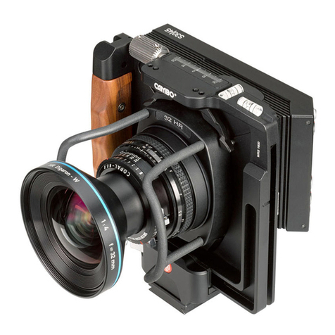
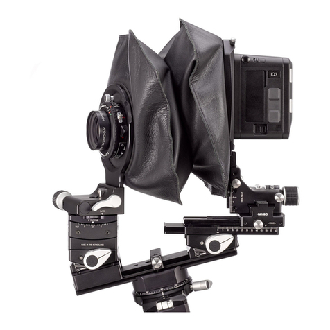
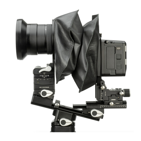
Cambo WDS-619 Operating instructions

This Manual is prepared by Cambo with care, although no responsibility, financial or otherwise, is accepted for any
consequences arising out of the use of this manual or this material.
All specifications in this manual are subject to change without notice. Check on www.cambo.com for updates.
Cambo is a registered trademark. All other mentioned trademarks are owned by their specific owners..
8
CAMBO FOTOGRAFISCHE INDUSTRIE BV
P.O. BOX 200
NL-8260 AE KAMPEN
THE NETHERLANDS
Tel. +31 383314644
Fax. +31 383315110
Web: w.cambo.com 2011
M. WDS-619 / WDS-630 viewing loupe
31.
32.
33.
34.
35.
36.
37.
38.
39.
MAIN OPERATING INSTRUCTIONS
CS-30 viewing loupe 3x (Schneider Optics)
Dioptre adjustment
Eyecup, silicone (turn to change left/right)
Bellows, silicone (removable)
Strap/lanyard mount
Shift frame (magnet connection)
Fold-away frame
WDS-619 ground-glass frame
Unlock lever (unlock fold-away frame)
Wide RS

J. USE OF LENSPANELS
In order to take the most advantage of the lenses that are used, please understand that every
lens has a limited image circle and viewing angle specified by the lens manufacturer.
Generally the indicated image circle is what the lens manufacturer has defined as committing to
the quality standards for that specific lens. Cambo does not change these specifications and users are
referred to Rodenstock’s and Schneider’s information about these lenses.
Some specific notes on a few lenses:
WDS-544 uses a Rodenstock 5.6/23HR Digaron-S, image circle limited to 70mm, which means limited
shift possibilities, depending upon cropping. There is not yet a centre-filter available.
WDS-545 uses a Schneider 5.6/24XL Digitar, image circle limited to 60mm, which means almost
no shift possibilities, nevertheless depending upon cropping. There is a centre-filter available.
WDS-546 uses a Rodenstock 4.0/28HR Digaron-S, image circle limited to 70mm, which means limited
shift possibilities, depending upon cropping. There is NO centre-filter available.
WDS-551 uses a Schneider 5.6/35XL Digitar, image circle limited to 90mm, which means about
18mm shift possibilities, depending upon cropping. There is a centre-filter available.
WDS-552 uses a Rodenstock 4.0/35HR Digaron-S, image circle limited to 70mm, which means limited
shift possibilities, depending upon cropping. There is NO centre filter available.
For all other lenses above 35mm focal length there is no need for a centre filter.
K. WTS TILT-SWING LENSPANELS
Refer to paragraph 3.A for mounting the panel to the body.
The WTS Panel allows an angle adjustment between +5 and -5 degrees in both swing and tilt direction for
setting Scheimpflug corrections. These can be used separately
as well as simultaneously, using 2 adjustment knobs, top knob T for tilt, side knob S for swing.
The lens plane and CCD are parallel when the tilt and swing indicators are set to zero on the scale. This
zero-position is reached when the bearing snaps into the lock, where the drive knobs become slightly loose
by purpose.
To apply tilt only use knob T, to apply swing only use knob S. When needed, a combination of both can be
applied.
L. LENS CAST
Under certain circumstances there may be occurrence of lens cast, caused by the light striking
the CCD under an angle due to either shifts or very short focal length. The effect may differ quite
a lot from one CCD to another and is not a constant factor. This effect is acknowledged by all digital back
manufacturers and each have their own software solution for this.
We refer to the user manual of your specific digital back manufacturer to use the software tools provided
with your digital back.
2
7
NOTE: DO NOT force
beyond the +5/-5
boundary marks.
!

H. ACCESSORY MOUNT AND VIEWFINDER
1. INTRODUCTION
On top of the main housing is a standard accessory shoe mount (4) which can be used for third party
items based on the flash shoe mount or for Cambo’s WDS-580 viewfinder. This viewfinder is optional
and is not included with the Wide RS camera.
Thank you for choosing this Cambo
product. This manual will give you
basic information about the use and
features of the Wide RS camera.
2.
LIST OF FUNCTIONS
1.
2.
3.
4.
5.
6.
7.
8.
9.
10.
11.
12.
13.
14.
15.
16.
17.
18.
19.
20.
21.
22.
23.
24.
25.
26.
27.
28.
29.
30.
The WDS-580 viewfinder is a 120 degrees viewer used for indication of the framing of the image.
It comes with an included extension bracket. Masks are available for most focal lengths. The viewfinder
has a built-in sprit level for assistance with handheld shooting.
To mount the viewfinder slide it into the accessory mount from the backside of the camera. It can
be mounted with or without the extension bracket. The advantage of using the extension bracket
is that the viewfinder is lifted over the digital back closer to the eye of the photographer. Because
the extension bracket introduces an extra joint, Cambo does not guarantee that the spirit level inside the
viewfinder is exactly aligned with the ones on the main housing it selves.
Masks can be clipped to the front of the viewfinder. These masks feature a center pair of
crosshairs and a frame for the current 37x49/40x55 CCD format. Aside the frame there is a set
of millimeter scales which indicate the displacement of the images with the same amount of
shift applied. The mask can be rotated while mounted to switch between landscape and portrait position.
Masks are interchangeable on the WDS-580 viewfinder, release the masks by pulling close to the
bottom click position.
I. LED LIGHT
The Wide RS system includes a removable LED light (25) which is convenient for use in darker
environments, shining light over the distance scale, aperture and time settings of the lens. The actual
LED unit is shifted in a frame which clips underneath the accessory mount (4).
It can be removed if not needed or for battery replacement.
When new delivered, the LED can be in demonstration mode, which means it will turn off automatically
within four seconds. You may leave it this way, or take it out of demonstration mode by pressing and
holding until the light turns off (at least 20 seconds).
Simply press for full power and instant ON/OFF. Squeeze for full-range brightness control.
To replace batteries, separate the case halves by unsnapping them at the base by the key ring (note
small notch in key-ring hole). Remove old batteries and replaces with two CR-2016 lithium batteries with
the + visible. Realign the case halves and snap shut.
6
3
Main housing
Handgrip (left and right)
Cable release (removable)
Accessory mount
Lens-plate locking lever (left)
Lens-plate locking lever (right)
Drive knob for horizontal shift
Lens guards (exception: WTS and 28XL)
Flash contact
Cable release socket
Tripod mount block (removable)
Knobs for tripod mount
Spirit levels
Drive knob for rise & fall
Release knob interface plate (right)
Release knob interface plate (left)
Retainer hooks for interface plate
Adapter-plate (interchangeable)
Lens-plate + lens (interchangeable)
Millimeter scale for shift
Movement indicators horizontal
Millimeter scale for rise and fall
Movement indicators vertical
Left hand cable release option
Mount for LED light unit (removable)
WRS-333 LEVEL HEAD (optional) page 6
Level thumb screws
Locking knob, rotation
Spigot mount
Locking knob spigot mount
Scale, degrees

3. INSTRUCTIONS
E. MOVEMENTS - SHIFT - RISE & FALL
The Wide RS has movements for horizontal shift as well as vertical shifts, which can be used in
combination. These movements can be used for perspective control, for image displacement,
but also for stitching, which allows the user to take more advantage of the image circle of certain lenses,
or to create panoramas with the maximum viewing angle, or to create larger file sizes.
The horizontal shift is operated by drive-knob (7) which is located on top of the main housing. The drive
has an accelerated gear, which moves fast and precise. From the center position
movements go up to either 20mm left or 20mm right, with click indents each 5, 10 and 15mm.
The vertical shift (rise & fall) is operated by drive-knob (14) on the right-hand side of camera.
The vertical shift allows for 25mm down towards the lens, which places the image up to 25mm upwards, or
up to 15mm up from the lens-center, which places the images up to 15mm downwards. Also here are click
indents every 5, 10, 15 and 20mm.
Both movements drive the image plane, which allows the user to take multiple images within the same
focal plane, ideal for stitching. There are several popular stitching programs, including Photoshop’s photo
merge tool.
Please note that above movements are the mechanically feasible movements, which do not by default
reflect the optical possibilities of all lenses. Each lens has its own possibilities and limits. For optical
explanations see chapter J. (use of lens-panels)
The main housing (1) accepts WDS/WTS-lens-panels on the front and SLW-Interface plates on
the backside. WDS lens-panels are available in a broad variety between 23 and 120 mm focal lengths
and with other focal lengths on special request. WTS lens-panels are specific lengths.
A. MOUNTING A LENSPANEL
To mount a WDS lens-panel (19) lift the 2 levers (5), slide the bottom of the Lens-plate into the slot
at the bottom side of the main housing, put the lens-panel in place and lock both levers (5).
The lens-guards (8) will help you to get a good grip on the lens-panels. Note: the WTS and 28XL lens-
panels don't feature lens-guards, because of limited clearance around the lens. The lens-guards may
come positioned in either way, top to bottom or left to right mounted. The position cannot be changed.
Note that the lenses look to be mounted reversed, however, this is for your convenience, to avoid
the cable release hanging in front of the lens, and to give easier access to the shutter’s cocking lever in
handheld position.
B. MOUNTING AN INTERFACE PLATE
Regarding SLW interface plates, there is a current choice between SLW-80 for Hasselblad-V
compatible backs, SLW-89 for Hasselblad-H compatible backs, SLW-81 for Leaf Afi/Sinar HY6
compatible backs, SLW-88 for PhaseOne/Mamiya 645 Afd compatible backs and SLW-87 for Contax
645 compatible backs. All plates are interchangeable.
F. MOVEMENTS AND SCALES
The horizontal movement can be followed and repeated viewing the scale (20) on top of the main housing.
The scale is divided into millimeters for your convenience. There are also movement indicators (21)
engraved on the back side of the main housing which are always visible from
behind the camera either under or above the vertical moving plate, depending upon its position.
The vertical movement can be followed and repeated viewing the scale (22) on right-hand side
of the main housing. The scale is divided into millimeters for your convenience. There are also movement
indicators (23) engraved on the left-hand back side of the horizontally moving plate which are always
visible from behind the camera, independent of the position of the plates.
To mount a SLW interface plate, shift the two knob-sliders (15,16) diagonal towards each other.
The interface plate (18) can be hooked firmly under the retainers (17), then put the interface
plate flat and lock the two knob-sliders over the interface plate. Interface plates can be mounted
in landscape position, or portrait 90 degrees left or 90 degrees right, whichever way is more convenient
for you in relation to access to CF-cards, batteries or cable locations.
There is an option for a Ground Glass Frame with CCD-markings (WDS-619). This frame mounts
in exactly the same way like the interface plates and replaces the interface plate while viewing.
C. HANDGRIPS AND CABLE RELEASE
G. TRIPOD MOUNTING BLOCK
The Wide RS comes with a removable tripod mounting block, which is already mounted in place.
It is equipped with a 3/8” thread. To ensure maximum protection of your investment, Cambo strongly
advises you to utilize the 3/8” thread of your tripod or quick release plate.
The height of the mounting block (11) allows the user to take full advantage of the 25mm vertical shift
when mounted on a larger tripod. However, to minimize the size of your camera, this
mounting block can be removed by disengaging the two larger screw studs (12). There will still be a 3/8”
mount in the bottom frame of the main housing.
G2. WRS-333 LEVEL HEAD
The optional Level Head replaces the original mount using both studs (12). The Level Head can be fine-
leveled with 3 individual thumbscrews (26), 2 for horizon and 1 for perpendicular setting. The Head with
Camera can be rotated 360 degrees, with clear detents at both 180 positions, in order to perform lens
settings at your convenience and swivel the Head back to original position. Each and any position else
can be locked with the knob (27).
The WRS Level Head also features a Spigot Mount (28) at the front to facilitate any accessory of your
choice such as lens shades, flags or sun shades.
The main housing has two integrated handgrips (2) which allow for steady handheld shooting.
Both handgrips have a hole (24) for hosting the cable release (3) on either left-hand or right-hand side by
choice. The cable release is easily removable for independent use when vibrations need
to be avoided. The cable release needs to be connected to the cable release socket (10) on the WDS
lens-panel. All lens-panels with either Schneider or Rodenstock lenses will have a Copal 0 shutter, with
shutter speeds between 1/500 and 1 second, B and T. These shutters need to be cocked between each
capture. The Schneider Electronic Shutter is only available on request.
D. MOUNTING THE DIGITAL BACK
The SLW interface plate has a great similarity to the corresponding Medium format camera that
the digital back is supposed to be compatible with. The Hasselblad-V, Mamiya Afd and Contax
645 interface plates have no moving parts. The Hasselblad-H interface plate has one sliding knob above
the digital back (in landscape position) to open and lock the digital back in place, while the Leaf Afi/Sinar
HY6 interface plate has a locking lever that operates all four pins simultaneously.
All digital backs need to be connected with their brand-specific “synchro release cable” to the synchro flash
contact (9) on the WDS lens-panels. Please follow the instructions of the manufacturer of the digital back
for further settings and operation.
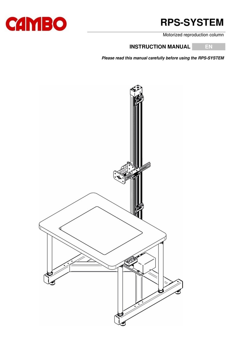
4
5
This manual suits for next models
1
Other Cambo Camera Accessories manuals

Cambo
Cambo PCF User manual

Cambo
Cambo Wide DS 38 XL Operating instructions

Cambo
Cambo PCH User manual

Cambo
Cambo PCS User manual

Cambo
Cambo CS-BRONTO User manual

Cambo
Cambo WRS-1060 User manual

Cambo
Cambo CS-32 User manual

Cambo
Cambo Wide DS Digital Series Operating instructions

Cambo
Cambo CSMFC-22 User manual

Cambo
Cambo Wide RS 1600 Series User manual