manuals.online logo
Brands
  1. Home
  2. •
  3. Brands
  4. •
  5. CAMDEN
  6. •
  7. Door Opening System
  8. •
  9. CAMDEN CX-95S-DH User manual

CAMDEN CX-95S-DH User manual

Magnetic Door Holders
CX-95S-DH Magnetic Door Holder
INSTALLATION INSTRUCTIONS
THIS PACKAGE INCLUDES:
1 x Door holder
4 x Wall Plugs
6 x M4 Self Tapping Screws
1 x Armature Plate
1 x Hex Key
1 X Manual
1. GENERAL DESCRIPTION
The Camden CX-95S-DH Magnetic Door Holder is designed for virtually
any remote door release application. The UL-listed Camden Magnetic
Door Holders control the release and closing of commercial and public
area doors, including apartments, schools, hotels, hospitals, and oces.
Fail-safe operation, tri-volt coils, and an adjustable armature plate allow
for easy and exible installation. Camden magnetic door holders may be
surface or ush mounted, with all mounting hardware included in the kit.
2. SPECIFICATIONS
Operating Voltage 12V 24V 120V
Supply AC DC AC DC AC DC
Current Draw 55mA 57mA 32mA 34mA 30mA -
Holding Force Up to 30 lbs. Up to 35 lbs. Up to 18 lbs.
Mount Options Surface or Flush mount
Dimensions
Surface mount Magnet:
2-3/4” W x 4-5/8” L x 2-1/2” D
(70mm x 116mm x 62mm)
Flush mount Magnet:
2-3/4” W x 4-5/8” L x 1-3/4” D
(70mm x 116mm x 44mm)
Armature:
2-9/16” W x 2-9/16” L x 2-7/8” D
(65mm x 65mm x 74mm)
3. DIMENSIONS
Page 1 of 2
Figure 3.2 Flush Mount
Figure 3.1 Armature Plate
Figure 3.3 Surface Mount
Ø2 1/8"
[55mm]
1 7/8"
[47mm]
2 3/4"
[70mm]
4 5/8"
[116mm]
4 5/8"
[116mm]
2 3/4"
[70mm]
2 1/2"
[62mm]
2 3/4"
[70mm]
4 5/8"
[116mm]
1 3/4"
[44mm]
1"
[26mm]
3/4"
[18mm]
2"
[50mm]
3 1/4"
[84mm]
2 3/8"
[60mm]
2"
[50mm]
Figure 3.1 Armature Plate
Figure 3.2 Flush Mount
Figure 3.3 Surface Mount
Wall
2 7/8"
[74mm]
2 7/8"
[74mm]
1 7/8"
[47mm]
2 1/2"
[65mm]
Ø2 9/16"
[65mm]
Wall
CX-95S-DH
Surface Mount
CX-95S-DH
Flush Mount
CX-95S-DH
Armature Mounting
Side
Ø2 1/8"
[55mm]
1 7/8"
[47mm]
2 3/4"
[70mm]
4 5/8"
[116mm]
4 5/8"
[116mm]
2 3/4"
[70mm]
2 1/2"
[62mm]
2 3/4"
[70mm]
4 5/8"
[116mm]
1 3/4"
[44mm]
1"
[26mm]
3/4"
[18mm]
2"
[50mm]
3 1/4"
[84mm]
2 3/8"
[60mm]
2"
[50mm]
Figure 3.1 Armature Plate
Figure 3.2 Flush Mount
Figure 3.3 Surface Mount
Wall Wall
2 7/8"
[74mm]
2 7/8"
[74mm]
1 7/8"
[47mm]
2 1/2"
[65mm]
Ø2 1/2"
[65mm]
Ground Wire
Black Wire
Electrical Grounding
Screw
ONLY WHEN USING 120V
White Wire
Side
Ø2 1/8"
[55mm]
1 7/8"
[47mm]
2 3/4"
[70mm]
4 5/8"
[116mm]
4 5/8"
[116mm]
2 3/4"
[70mm]
2 1/2"
[62mm]
2 3/4"
[70mm]
4 5/8"
[116mm]
1 3/4"
[44mm]
1"
[26mm]
3/4"
[18mm]
2"
[50mm]
3 1/4"
[84mm]
2 3/8"
[60mm]
2"
[50mm]
Figure 3.1 Armature Plate
Figure 3.2 Flush Mount
Figure 3.3 Surface Mount
Wall
2 7/8"
[74mm]
2 7/8"
[74mm]
1 7/8"
[47mm]
2 1/2"
[65mm]
Ø2 9/16"
[65mm]
Wall
CX-95S-DH
Surface Mount
CX-95S-DH
Flush Mount
CX-95S-DH
Armature Mounting
Side
4. INSTALLATION
1. Decide on the location for both the Magnetic Door Holder and the
Armature Plate.
2. Select the voltage for the Door Holder by setting the jumpers (two
jumpers for 12VAC/VDC, or one jumper for 24VAC/VDC or 120VAC)
(See Figure 4.3).
Surface Mount Magnetic Door Holder:
3. Use a pencil to mark the position for the mounting holes.
4. Drill holes at the marked positions using a 15/64” drill bit and insert
the provided wall plugs.
5. Align the magnetic door holder back box with the holes and let the
connecting wires pass through the center hole of the back box.
6. Secure the back box using the four M4 self-tapping screws provided in
the part kit .
7. Connect the wires according to the wiring diagram shown in gure 4.2.
8. Attach the magnetic door holder to the back box using the two M3x6
Phillips head screws provided.
9. Finally, attach the faceplate using the two M3x20 Phillips at head
screws.
Flush Mount Magnetic Door Holder
10. Connect the wires according to the wiring diagram as shown in Figure
4.2.
11. Mount the magnetic door holder using the two M3x6 Phillips head
screws provided.
12. Attach the faceplate using two M3x20 Phillips at head screws.
Ø2 1/8"
[55mm]
1 7/8"
[47mm]
2 3/4"
[70mm]
4 5/8"
[116mm]
4 5/8"
[116mm]
2 3/4"
[70mm]
2 1/2"
[62mm]
2 3/4"
[70mm]
4 5/8"
[116mm]
1 3/4"
[44mm]
1"
[26mm]
3/4"
[18mm]
2"
[50mm]
3 1/4"
[84mm]
2 3/8"
[60mm]
2"
[50mm]
Figure 3.1 Armature Plate
Figure 3.2 Flush Mount
Figure 3.3 Surface Mount
Wall Wall
2 7/8"
[74mm]
2 7/8"
[74mm]
1 7/8"
[47mm]
2 1/2"
[65mm]
Ø2 1/2"
[65mm]
Ground Wire
Black Wire
Electrical Grounding
Screw
ONLY WHEN USING 120V
White Wire
Side
CX-95S-DH Maglock Door Hold
INSTALLATION INSTRUCTIONS
Page 2 of 2
Figure 4.1 Installation of Magnetic Door Holder
Set the voltage using the jumpers as in gure 5.1.
NOTE: The factory default is 24VDC. To avoid personal injury or damage to the product, ensure that the jumper setting matches the wiring connections
and the supplied voltage. Improper settings/wiring will void the warranty and Camden will not be responsible for any resulting injury.
Door
Armature
plate
Door
Holder
Door
Armature
plate
Door
Holder
Flush mount Surface mount
RHS
Figure 6.2 Call: 1.877.226.3369 / 905.366.3377
Visit: www.camdencontrols.com
Opening New Doors to
Innovation, Quality and Support!
File: CX-95S-DH Magnetic Door Holder
Rev.: 19/09/2023
Part No.: 40-82B323
Wiring Diagram
0V 12V 24V120V
(+)
(-)
12 V
Setting
Voltage Jumper
Conguration 24 V
Setting 120 V
Setting
(+) (+)
(-) (-)
0V 12V 24V120V
Voltage Jumper
Conguration
0V 12V 24V120V
Voltage Jumper
Conguration
Wall
21
2"
[65.0mm]
15
8"
[41.4mm]
13
4"
[45.1mm]
Wall
Side
Figure 4.2 Exploded View
Armature Plate
13. Mark the location of armature on the door, making sure it lines up with
the door holder (extensions are available if needed.) (See Figure 4.2).
14. Drill holes at the marked positions using a 1/8” drill bit and mount the
armature using M4 Self-tapping screws.
15. Double-check all connections and mountings to make sure the installa-
tion is complete.
Important: The wiring connections must match the voltage
jumper settings and the supplied voltage.
Wall
21
2"
[65.0mm]
15
8"
[41.4mm]
13
4"
[45.1mm]
Wall
Side
Surface Mount
Flush Mount
Armature Plate (Top View)
5. WIRING
Figure 5.1 Wiring
Diagram
• When utilizing a 120 V AC power source, it is essential to securely attach
the ground wire to the designated electrical grounding screw, as illustrated
in Figure 5.2.
Ø2 1/8"
[55mm]
1 7/8"
[47mm]
2 3/4"
[70mm]
4 5/8"
[116mm]
4 5/8"
[116mm]
2 3/4"
[70mm]
2 1/2"
[62mm]
2 3/4"
[70mm]
4 5/8"
[116mm]
1 3/4"
[44mm]
1"
[26mm]
3/4"
[18mm]
2"
[50mm]
3 1/4"
[84mm]
2 3/8"
[60mm]
2"
[50mm]
Figure 3.1 Armature Plate
Figure 3.2 Flush Mount
Figure 3.3 Surface Mount
Wall Wall
2 7/8"
[74mm]
2 7/8"
[74mm]
1 7/8"
[47mm]
2 1/2"
[65mm]
Ø2 1/2"
[65mm]
Ground Wire
Black Wire
Electrical Grounding
Screw
ONLY WHEN USING 120V
White Wire
Side
Figure 5.2 Connection with
Grounding Screw connection for 120V AC Setting
Important note for 120 V Setting
7”

Other CAMDEN Door Opening System manuals

CAMDEN CM-300 User manual

CAMDEN

CAMDEN CM-300 User manual

CAMDEN CM-300 User manual

CAMDEN

CAMDEN CM-300 User manual

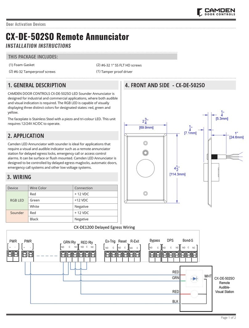
CAMDEN CX-DE-502SO User manual

CAMDEN

CAMDEN CX-DE-502SO User manual

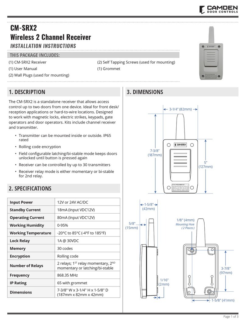
CAMDEN CM-SRX2 User manual

CAMDEN

CAMDEN CM-SRX2 User manual

CAMDEN CM-47-ADP1 User manual

CAMDEN

CAMDEN CM-47-ADP1 User manual

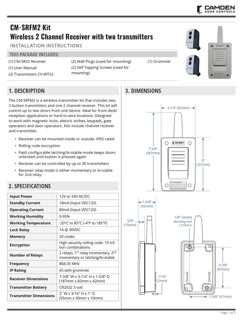
CAMDEN CM-SRFM2 Kit User manual

CAMDEN

CAMDEN CM-SRFM2 Kit User manual

CAMDEN CM-550SK-V2 User manual

CAMDEN

CAMDEN CM-550SK-V2 User manual

CAMDEN Lazerpoint CM-TXLF Series User manual

CAMDEN

CAMDEN Lazerpoint CM-TXLF Series User manual

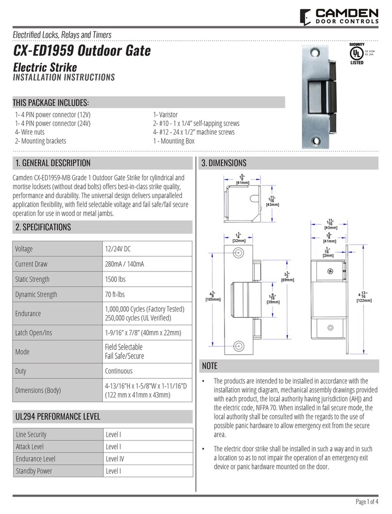
CAMDEN CX-ED1959 User manual

CAMDEN

CAMDEN CX-ED1959 User manual

Popular Door Opening System manuals by other brands

Hard Head 316-414 User instructions

Hard Head

Hard Head 316-414 User instructions

Label NEXT 120s installation manual

Label

Label NEXT 120s installation manual

Abus PR2700 Fitting and operating instructions

Abus

Abus PR2700 Fitting and operating instructions

Label NEPTIS/LE installation manual

Label

Label NEPTIS/LE installation manual

Label ETERNA 90 EASY installation manual

Label

Label ETERNA 90 EASY installation manual

Entrematic Ditec LOKSB installation manual

Entrematic

Entrematic Ditec LOKSB installation manual

Nice SUMO Instructions and warnings for the fitter

Nice

Nice SUMO Instructions and warnings for the fitter

Optex OA-AXIS I manual

Optex

Optex OA-AXIS I manual

Dorma TS 68 manual

Dorma

Dorma TS 68 manual

CDVI DIGIWAY PLUS manual

CDVI

CDVI DIGIWAY PLUS manual

Assa Abloy Corbin Russwin PED159 installation instructions

Assa Abloy

Assa Abloy Corbin Russwin PED159 installation instructions

Autoslide AutoSwing ASW8-1 installation manual

Autoslide

Autoslide AutoSwing ASW8-1 installation manual

Ribind UP manual

Ribind

Ribind UP manual

CAME C-BX installation manual

CAME

CAME C-BX installation manual

GEZE TS4000 installation instructions

GEZE

GEZE TS4000 installation instructions

Tormax TTXII Installation and operating manual

Tormax

Tormax TTXII Installation and operating manual

TdA PE200B Installation and user manual

TdA

TdA PE200B Installation and user manual

CDV Group DIGIWay DWS102 Series Use and installation  manual

CDV Group

CDV Group DIGIWay DWS102 Series Use and installation manual

manuals.online logo
manuals.online logoBrands
  • About & Mission
  • Contact us
  • Privacy Policy
  • Terms and Conditions

Copyright 2025 Manuals.Online. All Rights Reserved.