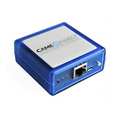
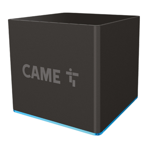
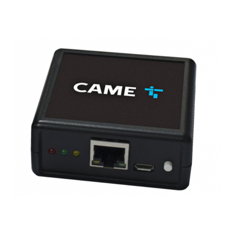
CAME CONNECT GW Instruction sheet

B A 2 10
FA00386M04
Manuale di configurazione
CONNECT GW
Modulo gateway

B A 2 10
Pag. 2- Codice manuale: FA00386-IT ver. 104/2016 © CAME s.p.a. - I dati e le informazioni indicate in questo manuale sono da ritenersi suscettibili di modifica in qualsiasi momento e senza obbligo di preavviso.
INFORMAZIONI GENERALI
Per connettere una o più automazioni al portale CAME Cloud o ad una rete locale
dedicata e rendere possibile la gestione da remoto delle funzioni associate alle
automazioni comandate, è necessario che sull’impianto sia presente un gateway
(CONNECT GW) il quale permette all’impianto di essere connesso ad una rete.
L’installazione e configurazione di questo modulo deve essere eseguita da
personale qualificato ed adeguatamente formato.
CONFIGURAZIONE DEL MODULO CONNECT GW
Il modulo permette di interfacciare una o più automazioni alla rete in diverse
modalità:
• attraverso la propria rete Wi-Fi, mediante l’apposita antenna connessa alla presa
USB,
• attraverso un cavo LAN che dallo switch arriva fino all’adattatore USB-LAN del
modulo,
• attraverso la rete GSM, mediante scheda telefonica e antenna da montare negli
appositi alloggiamenti.
☞ Maggiori informazioni sulle caratteristiche tecniche e sui collegamenti del
gateway sono presenti sulle istruzioni CONNECT GW.
Download ed installazione del software
“Connect GW Configurator”
Qualunque sia la modalità di connessione scelta, il gateway necessita di apposita
programmazione dell’interfaccia di rete; a questo scopo è necessario scaricare
l’ultima versione del software “Connect GW Configurator” dal seguente link:
http://www.cameconnect.net/came/pages/download.html
☞ Il software può essere installato in PC dotati di processore Pentium, 2GB di
memoria, 50 MB di spazio libero sull’hard disk e sistema operativo Microsoft®
Windows 7 o successivo.
Installare l’applicazione sul proprio PC seguendo le indicazioni.

Pag. 3- Codice manuale: FA00386-IT ver. 104/2016 © CAME s.p.a. - I dati e le informazioni indicate in questo manuale sono da ritenersi suscettibili di modifica in qualsiasi momento e senza obbligo di preavviso.
Descrizione dei parametri di configurazione
Lanciare l’applicazione “Connect GW Configurator” facendo doppio clic sull’icona sul
desktop o nel menu Start di Windows.
❶Permette di scegliere una delle lingue disponibili per l’interfaccia
dell’applicazione.
La finestra principale del configuratore è composta da due sezioni.
La sezione [Server]
Stabilisce il tipo di server con il quale il modulo deve comunicare:
❷Scegliere questa opzione se si vogliono controllare i dispositivi connessi al
modulo attraverso il cloud Came all’url http://www.cameconnect.net.
❸Scegliere questa opzione se si vogliono controllare i dispositivi connessi al
modulo attraverso un server locale presente nella vostra LAN.
Nel campo [Indirizzo IP / nome host] inserire l’indirizzo IP del server CameConnect
locale o il suo nome host.
Se viene specificato il nome host invece dell’indirizzo IP, è obbligatorio
specificare l’indirizzo IP del server DNS nella sezione [Connettività].
Nel campo [Porta] indicare la porta IP utilizzata dai servizi CameConnect locali
(generalmente 8080 è il valore di default).
❹Scegliendo questa opzione il gateway è in grado di rispondere ad una richiesta
esterna senza essere connesso ad alcun server.
Solo per integrazione con altri sistemi.
La sezione [Connettività]
Definisce e configura la modalità utilizzata dal modulo per connettersi al server.
❺Scegliere una delle 3 modalità di connessione disponibili:
Connettività [Ethernet]
Scegliere questa modalità se il modulo è connesso ad una rete LAN cablata.
❻Scegliere questa opzione se la rete privata alla quale è connesso il modulo
dispone di un server DHCP il quale assegnerà un indirizzo IP (dinamico) al modulo ad
ogni avvio.
❷
❸
❹
❶
❺
❻

Pag. 4- Codice manuale: FA00386-IT ver. 104/2016 © CAME s.p.a. - I dati e le informazioni indicate in questo manuale sono da ritenersi suscettibili di modifica in qualsiasi momento e senza obbligo di preavviso.
❼Scegliere questa opzione se si desidera assegnare al modulo uno specifico
indirizzo IP (statico); è necessario che l’indirizzo appartenga alla stessa sottorete
(subnet) del router. Completare i campi con i dati della propria rete locale. Connettività [Wifi]
Scegliere questa modalità se il modulo è connesso ad una rete Wi-Fi attraverso
l’apposita antenna.
Verificare che la posizione prescelta per l’installazione del modulo sia
raggiungibile dal segnale Wi-Fi (per esempio con l’aiuto di uno smartphone).
❶Digitare il nome della rete Wi-Fi alla quale il modulo dovrà connettersi (SSID =
Service Set ID).
Il modulo può gestire solo nomi di reti SSID che NON contengono spazi.
Caratteri ammessi:
lettere minuscole [ a-z ], lettere maiuscole [ A-Z ], cifre decimali [ 0-9 ],
simboli [ ` ~ ! @ # $ % ^ ( ) _ - + = { } [ ] \ | : ; , . ? / ]
❷Se la rete è protetta indicare il tipo di crittografia adottata.
❸Digitare l’eventuale pasword che protegge la rete Wi-Fi da accessi indesiderati.
❹Generalmente per le reti Wi-Fi questa modalità è quella corretta, tuttavia è
possibile assegnare al modulo uno specifico indirizzo IP (statico); è necessario che
l’indirizzo appartenga alla stessa sottorete (subnet) del router.
Completare i campi con i dati della propria rete locale.
❼
❶
❷
❹
❸

B A 2 10
Pag. 5- Codice manuale: FA00386-IT ver. 104/2016 © CAME s.p.a. - I dati e le informazioni indicate in questo manuale sono da ritenersi suscettibili di modifica in qualsiasi momento e senza obbligo di preavviso.
Connettività [GSM]
Scegliere questa modalità se il modulo è connesso ad internet attraverso una rete
mobile GSM/GPRS.
Questo tipo di configurazione ha
bisogno che sul modulo sia montata
una scheda SIM abilitata al traffico dati.
É consigliabile contattare l’operatore di
telefonia mobile scelto per ottenere le
informazioni necessarie a configurare
correttamente i parametri richiesti.
❺[APN] ( Access Point Name) è
il parametro essenziale da inserire;
permette al modulo di identificare la rete esterna mediante la quale la scheda
telefonica può accedere ai servizi Internet. Generalmente gli operatori di telefonia
pubblicano questa informazione nei propri siti internet.
❻Codice telefonico composto dal sistema per creare la connessione a internet.
Non modificare il contenuto del campo; compilare diversamente solo se richiesto
dall’operatore GSM.
❼Alcuni operatori GSM richiedono l’inserimento di questi dati (compilare solo se
richiesto dall’operatore GSM).
Configurare le automazioni in assenza di server
Se alla sezione [Server] si è scelta l’opzione [Nessun server], nella parte alta della
schermata di configurazione, viene attivata una sezione [Automazioni] la quale
permette di configurare le caratteristiche delle automazioni con le quali il modulo
deve comunicare.
❶Il pulsante permette di aggiungere una nuova automazione controllata dal
gateway.
❷Inserire una descrizione dell’automazione utile alla sua facile individuazione.
❸Selezionare il tipo di quadro di comando al quale l’automazione è collegata.
❺
❻
❼
❶
❷
❸

Pag. 6- Codice manuale: FA00386-IT ver. 104/2016 © CAME s.p.a. - I dati e le informazioni indicate in questo manuale sono da ritenersi suscettibili di modifica in qualsiasi momento e senza obbligo di preavviso.
Trasferire la configurazione nel modulo
Una volta configurati i parametri necessari al tipo di connettività scelta, dal menù
[File] selezionando la voce [Salva], vengono generati 2 file.
I file generati devono essere salvati al primo livello di una chiave USB.
Accertarsi che al primo livello (root) della chiave USB non siano presenti altri files
di configurazione.
Accertarsi che il modulo gateway CONNECT GW non sia alimentato e che tutti i
connettori siano rimossi dalla loro sede.
1. Inserire la chiave nella quale si sono salvati i file di configurazione, nel connettore
USB del gateway CONNECT GW e ripristinare l’alimentazione.
2. Il LED rosso DL4 si accende seguito dal lampeggio del LED rosso DL3.
3. Il LED rosso DL3 lampeggia velocemente per alcuni secondi durante la fase di
impostazione della configurazione.
4. Lo spegnimento del LED DL3 indica che la configurazione è stata salvata nel
modulo.
5. Disalimentare il modulo
6. Rimuovere l’unità USB ed eventualmente reinserire il convertitore USB-LAN o
USB-WiFi.
7. Ripristinare l’alimentazione; il modulo è operativo.
❹Aggiunge nuove automazioni alla lista di quelle già presenti nel modulo.
❺Cancella la lista presente nel modulo e ne crea una nuova.
❻Indicare il numero periferica assegnato all’automazione; il dato è particolarmente
importante nel caso in cui ad un medesimo quadro di comando facciano capo più
automazioni.
☞Il valore è “1” nelle impostazioni di fabbrica dei quadri di comando CAME.
❼Permette di modificare la configurazione dell’automazione selezionata.
❽Rimuove dall’elenco l’automazione selezionata.
❾Cancella tutte le automazioni dall’elenco.
❻
❹
❼
❺
❽ ❾

cameGSM_
FW.tar.gz.enc cameGSM_FW.
bin
Pag. 7- Codice manuale: FA00386-IT ver. 104/2016 © CAME s.p.a. - I dati e le informazioni indicate in questo manuale sono da ritenersi suscettibili di modifica in qualsiasi momento e senza obbligo di preavviso.
Aggiornamento manuale del firmware
Scaricare dal seguente link:
http://www.cameconnect.net/came/pages/download.html
l’ultima versione dei files cameGSM_FW.tar.gz.enc e cameGSM_FW.bin contenenti
l’aggiornamento firmware.
I file scaricati devono essere salvati al primo livello di una chiave USB.
Accertarsi che al primo livello (root) della chiave USB non siano presenti altri files
di configurazione.
Impostazioni [Avanzate]
Permettono di abilitare l’aggiornamento automatico del modulo. Con questa funzione
attiva, il modulo installa autonomamente eventuali aggiornamenti firmware resi
disponibili dal server indicato.
☞ Le impostazioni di fabbrica prevedono che l’aggiornamento automatico sia
disabilitato.
Il processo di aggiornamento automatico mette fuori servizio per alcuni minuti
il modulo e quindi il collegamento a CAMEConnect; le automazioni continuano a
funzionare regolarmente.
Accertarsi che il modulo gateway CONNECT GW non sia alimentato e che tutti i
connettori siano rimossi dalla loro sede.
1. Inserire la chiave nella quale è stato salvato il nuovo firmware, nel connettore USB
del gateway CONNECT GW e ripristinare l’alimentazione.
2. Il LED rosso DL4 si accende seguito dal lampeggio del LED rosso DL3.
3. Il LED rosso DL3 lampeggia velocemente per alcuni secondi durante la fase di
aggiornamento firmware.
4. Lo spegnimento del LED DL3 indica che il processo di aggiornamento è terminato.
5. Disalimentare il modulo
6. Rimuovere l’unità USB ed eventualmente reinserire il convertitore USB-LAN o
USB-WiFi.
7. Ripristinare l’alimentazione; il modulo è operativo.
☞ L’aggiornamento firmware non cancella o modifica la configurazione esistente del
modulo gateway.

Came S.p.A.
Via Martiri Della Libertà, 15 Via Cornia, 1/b - 1/c
31030 Dosson di Casier - Treviso - Italy 33079 Sesto al Reghena - Pordenone - Italy
(+39) 0422 4940 – (+39) 0422 4941 (+39) 0434 698111 – (+39) 0434 698434
www.came.com
Pag. 8- Codice manuale: FA00386-IT ver. 104/2016 © CAME s.p.a. -
I dati e le informazioni indicate in questo manuale sono da ritenersi suscettibili di modifica in qualsiasi momento e senza obbligo di preavviso.

B A 2 10
FA00386-EN
Configuration manual
CONNECT GW
Gateway module

B A 2 10
p. 2- Manual code: FA00386-EN v. 104/2016 © CAME S.p.A. The data and information in this manual may be changed at any time and without notice.
GENERAL INFORMATION
To connect one or more operators to the CAME Cloud portal or to a dedicated local
network so as to remotely manage the functions featured on the operators you are
managing, there must be a CONNECT GW gateway module installed on your system.
This permits your system link up to a network.
This module must only be installed and configured by qualified trained and
skilled sta.
CONFIGURING THE CONNECT GW MODULE
The module is for interfacing one or mode operators to the network, in dierent
modes:
• through your Wi-Fi network, via the corresponding antenna connected to the USB
port,
• through a LAN cable from the switch to the module's USB-LAN adapter,
• through the GSM network, via the telephony card and antenna to fit into the
corresponding housings.
☞ You can find more information and technical characteristics about the gateway
module in the CONNECT GW instructions.
Download and install the "Connect GW Configurator"
software
Despite the connective mode you have chosen, the gateway module needs to
be properly programmed to interface with the network; that's why you need to
download the latest version of the “Connect GW Configurator” software from:
http://www.cameconnect.net/came/pages/download.html
☞ The software may be installed on PCs with Pentium processors, 2 GB of memory,
50 MB of free hard-disk space and running the Windows 7®or later Microsoft OS.
Install the application on your PC by following the instructions.

p. 3- Manual code: FA00386-EN v. 104/2016 © CAME S.p.A. The data and information in this manual may be changed at any time and without notice.
Description of the configuration parameters
Launch the "Connect GW Configurator" application by double-clicking on the
desktop icon or in the Windows Start menu.
❶Choose among the available languages for interfacing with the application.
The configurator's main window is composed of two sections.
The [Server] section
It determines which server type the module will communicate with:
❷Choose this option when you want to control devices that are Came cloud-
connected at the following url http://www.cameconnect.net.
❸Choose this option when you want to control devices that are connected to a local
server on your LAN.
In the [IP address / host name] field enter the local CameConnect server's IP
address or host name.
If you enter the host name instead of the IP address, you need to enter the DNS
server's IP address in the [Connectivity] section.
In the [Port] field enter the IP port used by the local CameConnect services -
generally, it is port 8080 plus the default value.
❹If you choose this option, the gateway can then reply to an external request
without being connected to any server.
Only for integrating with other systems.
The [Connectivity] section
It defines and configures which mode the module use to connect to the server.
❺Choose one of the three available connection modes:
Connetivity [Ethernet]
Choose this mode if the module is connected to a hardwired LAN.
❻Choose this option if the private network to which the module is connected
features a DHCP server which will assign a dynamic IP address to the module at
each launch.
❷
❸
❹
❶
❺
❻

p. 4- Manual code: FA00386-EN v. 104/2016 © CAME S.p.A. The data and information in this manual may be changed at any time and without notice.
❼Choose this option if you wish to assign a specific static IP address to the
module; the address must belong to the router's same subnet. Fill in the fields with
data from your local network. Connetivity [WiFi]
Choose this mode if the module is connected to a Wi-Fi network via a
corresponding antenna.
Check that the position you choose for installing the module is reachable by the
Wi-Fi signal (for example, with the aid of a smartphone).
❶Enter the name of the Wi-Fi network you wish the module to connect to (SSID =
Service Set ID).
The module can only manage SSID network names that are VOID of spaces.
Allowed characters:
lower case letters [ a-z ], upper case letters [ A-Z ], decimals [ 0-9 ],
symbols [ ` ~ ! @ # $ % ^ ( ) _ - + = { } [ ] \ | : ; , . ? / ]
❷If the network is protected, specify the type of cryptography you are using.
❸Enter any password that is protecting the Wi-Fi network from unauthorized access.
❹Generally, this is the proper mode for Wi-Fi networks. However, you can assign
a specific static IP address to the module; the address must belong to the router's
same subnet.
Fill in the fields with data from your local network.
❼
❶
❷
❹
❸

B A 2 10
p. 5- Manual code: FA00386-EN v. 104/2016 © CAME S.p.A. The data and information in this manual may be changed at any time and without notice.
Connetivity [GSM]
Choose this mode if the module connects to the internet via a mobile GSM/GPRS
network.
This type of configuration requires a
SIM card, enabled to process data, to
be plugged into the module
We suggest contacting your local
mobile carrier to get the information
needed to properly configure the
required parameters.
❺[APN] ( Access Point Name) is the
essential parameter to enter; it enables
the module to identify the external network through which the telephony card may
access the internet services. Generally, telephony operators post this information on
their websites.
❻Telephone code dialed by the system to establish an internet connection.
Leave the field contents unchanged; change only if required by your GSM
operator.
❼Some GSM operators require you to enter this data (only do so if required by your
local GSM operator).
Configuring the operators when no server is present
If in the [Server] section you chose the [No server] option, in the top part of
the configuration screen, this activated the [Operators] section which lets you
configure the characteristics of the operators that the module will communicate
with.
❶The button lets you add a new operator controlled by the gateway module.
❷Enter an easy-to-find description of the module.
❸Choose the type of control panel that will be connected to the operator.
❺
❻
❼
❶
❷
❸

p. 6- Manual code: FA00386-EN v. 104/2016 © CAME S.p.A. The data and information in this manual may be changed at any time and without notice.
Transfer the configuration into the module
Once you have configured the parameters required by the type of connectivity choice
you've made, from the [File] menu select item [Save], this generates two files.
These two generated files must be saved at the root level to a USB flash-drive.
Check that there are no other configuration files at the USB flash-drive's initial
(root) level.
Check that the CONNECT GW gateway module is powered OFF, and that all
connectors are unplugged from their sockets.
1. Fit the flash-drive, on which you previously saved the configuaration files, into the
USB port on the CONNECT GW module and then power ON again.
2. The red DL4 LED lights up and then the red DL3 LED flashes.
3. The red DL3 LED flashed quickly for some seconds while settings and
configurations are being processed.
4. When the red DL3 LED switches o, this means the configuration is now saved in
the module.
5. Power OFF the module.
6. Remove the USB unit and possibly refit the USB-LAN or USB-Wi-Fi converter.
7. Power ON the module; the module is ready to function.
❹Add new operators to the list of operators in the module.
❺Delete the list in the module and create a new list.
❻Show the peripheral number assigned to the operator; this number is very
important when multiple operators are controlled by one control panel.
☞The value is "1" in the factory settings of CAME control panels.
❼Edit the configuration of the chosen operator.
❽Remove the selected operator from the list.
❾Delete all operators from the list.
❻
❹
❼
❺
❽ ❾

cameGSM_
FW.tar.gz.enc cameGSM_FW.
bin
p. 7- Manual code: FA00386-EN v. 104/2016 © CAME S.p.A. The data and information in this manual may be changed at any time and without notice.
Manual firmware update
Download from:
http://www.cameconnect.net/came/pages/download.html
latest file versions cameGSM_FW.tar.gz.enc and cameGSM_FW.bin with firmware
updates.
You must save the downloaded update files at the root level of the USB flash-drive.
Check that there are no other configuration files at the USB flash-drive's initial
(root) level.
Settings [Advanced]
These are for enabling the module's automatic updates. When this function is on, the
module self-installs any firmware updates available on the corresponding server.
☞The factory settings have the automatic update feature switched o.
The automatic update process causes the module to go into an out-of-order-
state for some minutes, so as to link up to CAMEConnect; meanwhile, the operators
still function.
Check that the CONNECT GW gateway module is powered OFF, and that all
connectors are unplugged from their sockets.
1. Fit the flash-drive, on which you have saved the new firmware, into the USB port on
the CONNECT GW module and then power ON again.
2. The red DL4 LED lights up and then the red DL3 LED flashes.
3. The red DL3 LED flashes quickly for some seconds while the firmware updates.
4. When the red DL3 LED switches o, it means the updating is complete.
5. Powering OFF the module
6. Remove the USB unit and possibly refit the USB-LAN or USB-Wi-Fi converter.
7. Power ON the module; the module is ready to function.
☞Updating the firmware does not erase or change the gateway module's existing
configuration.

Came S.p.A.
Via Martiri Della Libertà, 15 Via Cornia, 1/b - 1/c
31030 Dosson di Casier - Treviso - Italy 33079 Sesto al Reghena - Pordenone - Italy
(+39) 0422 4940 – (+39) 0422 4941 (+39) 0434 698111 – (+39) 0434 698434
www.came.com
p. 8- Manual code: FA00386-EN v. 104/2016 © CAME S.p.A. -
The data and information in this manual may be changed at any time and without notice.

B A 2 10
FA00386-FR
Manuel de configuration
CONNECT GW
Module passerelle

B A 2 10
Page 2- Code manuel : FA00386-FR vers. 104/2016 © CAME s.p.a. Les données et les informations contenues dans ce manuel sont susceptibles de subir des modifications à tout moment et sans aucun préavis.
INFORMATIONS GÉNÉRALES
Pour connecter un ou plusieurs automatismes au portail CAME Cloud ou à un
réseau local dédié et permettre la gestion à distance des fonctions associées aux
automatismes commandés, l'ìnstallation doit être dotée d’une passerelle (CONNECT
GW) lui permettant d’être connectée à un réseau.
L’installation et la configuration de ce module doivent être confiées à un
personnel qualifié.
CONFIGURATION DU MODULE CONNECT GW
Le module permet l’interfaçage d’un ou de plusieurs automatismes avec le réseau
selon diérentes modalités :
• par le biais du propre réseau Wi-Fi, au moyen de l'antenne spécifique connectée à
la prise USB,
• par le biais d'un câble LAN de l'interrupteur à l'adaptateur USB-LAN du module,
• par le biais du réseau GSM, au moyen de la carte téléphonique et de l'antenne à
introduire dans les logements spécifiques.
☞ Vous trouverez sur les instructions CONNECT GW de plus amples informations
concernant les caractéristiques techniques et les connexions de la passerelle.
Téléchargement et installation du logiciel
« Connect GW Configurator »
Quelle que soit la modalité de connexion choisie, la passerelle requiert une
programmation spécifique de l'interface de réseau ; pour ce faire, il est nécessaire
de télécharger la dernière version du logiciel « Connect GW Configurator » à partir du
lien suivant :
http://www.cameconnect.net/came/pages/download.html
☞ Il est possible d’installer le logiciel sur des PC dotés d’un processeur Pentium,
d’une mémoire de 2 Go, de 50 Mo d’espace libre sur le disque dur et du système
d’exploitation Microsoft®Windows 7 ou version ultérieure.
Installer l’application sur PC en suivant les indications.

Page 3- Code manuel : FA00386-FR vers. 104/2016 © CAME s.p.a. Les données et les informations contenues dans ce manuel sont susceptibles de subir des modifications à tout moment et sans aucun préavis.
Description des paramètres de configuration
Lancer l'application « Connect GW Configurator » en double-cliquant sur l'icône
prévue sur le bureau ou bien dans le menu Démarrer de Windows.
❶Permet de choisir une des langues disponibles pour l'interface de l'application.
La fenêtre principale du configurateur se compose de deux sections.
La section [Serveur]
Permet d'établir le type de serveur avec lequel le module doit communiquer :
❷Choisir cette option pour contrôler les dispositifs connectés au module par le
biais du cloud Came dans l’url http://www.cameconnect.net.
❸Choisir cette option pour contrôler les dispositifs connectés au module par le
biais d'un serveur local présent dans votre LAN.
Dans le champ [Adresse IP / nom d'hôte], saisir l'adresse IP du serveur
CameConnect local ou son nom d'hôte.
En cas d'indication du nom d'hôte à la place de l'adresse IP, il est obligatoire de
spécifier l'adresse IP du serveur DNS dans la section [Connectivité].
Dans le champ [Port], indiquer le port IP utilisé par les services CameConnect locaux
(la valeur par défaut est généralement 8080).
❹Le choix de cette option permet à la passerelle de répondre à une demande
externe sans être connectée à aucun serveur.
Uniquement en cas d'intégration avec d'autres systèmes.
La section [Connectivité]
Permet de définir et de configurer la modalité de connexion du module au serveur.
❺Choisir une des trois modalités de connexion disponibles :
Connectivité [Ethernet]
Choisir cette modalité si le module est connecté à un réseau LAN câblé.
❻Choisir cette option si le réseau privé auquel le module est connecté dispose
d'un serveur DHCP qui attribuera une adresse IP (dynamique) au module à chaque
démarrage.
❷
❸
❹
❶
❺
❻

Page 4- Code manuel : FA00386-FR vers. 104/2016 © CAME s.p.a. Les données et les informations contenues dans ce manuel sont susceptibles de subir des modifications à tout moment et sans aucun préavis.
❼Choisir cette option pour attribuer au module une adresse IP (statique) spécifique
; cette adresse doit appartenir au même sous-réseau (subnet) que le routeur. Saisir
dans les champs les données du propre réseau local. Connectivité [Wifi]
Choisir cette modalité si le module est connecté à un réseau Wi-Fi par le biais de
l'antenne spécifique.
S'assurer que le signal Wi-Fi (à l'aide d'un smartphone par exemple) parvient à
atteindre le module à l'endroit où celui-ci a été installé.
❶Entrer le nom du réseau Wi-Fi auquel le module devra se connecter (SSID =
Service Set ID).
Le module ne peut gérer que des noms de réseaux SSID SANS espaces.
Caractères admis : lettres minuscules [ a-z ], lettres majuscules [ A-Z ], nombres
décimaux [ 0-9 ], symboles [ ` ~ ! @ # $ % ^ ( ) _ - + = { } [ ] \ | : ; , . ? / ]
❷Si le réseau est protégé, indiquer le type de cryptographie adoptée.
❸Saisir l'éventuel mot de passe qui protège le réseau Wi-Fi contre tout accès non
autorisé.
❹Cette modalité est généralement correcte pour les réseaux Wi-Fi même s'il est
possible d'attribuer au module une adresse IP (statique) spécifique ; cette adresse
doit appartenir au même sous-réseau (subnet) que le routeur.
Saisir dans les champs les données du propre réseau local.
❼
❶
❷
❹
❸
Table of contents
Languages:
Other CAME Gateway manuals
Popular Gateway manuals by other brands

Moxa Technologies
Moxa Technologies MGate 5101-PBM-MN Quick installation guide

Iseo
Iseo Zero1 user manual

ZyXEL Communications
ZyXEL Communications P-661HNU-FX quick start guide

Kerlink
Kerlink WIRNET IFEMTOCELL user manual

SMC Networks
SMC Networks LEC-GMJ2 Series instruction manual

ZyXEL Communications
ZyXEL Communications VMG1312-B10A Specifications