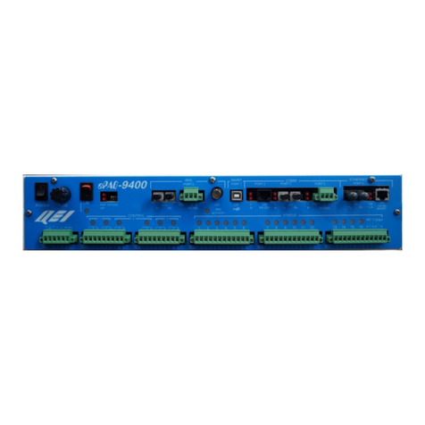
QEI ePAQ-9100 User manual

UG-1037
ePAQ-9100
December 2018

UG-1037 ePAQ-9100
Copyright © 2017 by QEI
UG-1037 ePAQ-9100
ALL RIGHTS RESERVED
NOTICE
The information in this document has been carefully checked and is believed to be
accurate. However, no responsibility is assumed or implied for inaccuracies. Further
more, QEI reserves the right to make changes to any products herein
described to improve reliability, function or design. QEI does not assume liability arising
out of the application or use of any product or circuit described herein; neither does it
convey any license under its patent rights nor the rights of others.
This manual and all data contained constitute proprietary information of QEI, Inc. and
shall not be reproduced, copied or disclosed to others, or used as the basis for
manufacture without written consent of QEI.
45 Fadem Road
Springfield, NJ 07081
Phone: (973) 379-7400
Fax: (973) 379-2138
Web Site: www.qeiinc.com

UG-1037 ePAQ-9100
Copyright © 2017 QEI Introduction 1
Revisions
Revision Description Date
A
Release to Production
November 2001
B
Added Network Interface
and Troubleshooting
Sections
September 2002
C
Revised Operating
Voltages
October 2008
D
Updated Ordering
Information
June 2009
E
Fixed Diagrams,
removed ConfigWiz
October 2010
F
Formatting Update
March 2012
G
Formatting Update
February 2016
H
Formatting Update
June 2017
I
Updated QEI Address
December 2018

UG-1037 ePAQ-9100
2 Introduction Copyright © 2017 QEI
Contents
1Introduction..............................................................................4
2Applications..............................................................................5
2.1 Substation Data Concentrator..............................................6
2.2 IED/SCADA Integration Platform..........................................7
2.3 Legacy RTU to Substation LAN Gateway.............................8
2.4 Substation LAN to Legacy SCADA/EMS Master..................9
2.5 SCADA Web Server...........................................................10
2.6 Automation Platform ..........................................................11
3Hardware Overview................................................................12
3.1 Main Processor and Memory.............................................12
3.2 Communications Interface .................................................12
3.2.1 Ports #1 and #2...................................................13
3.2.2 Port #3 (Maintenance Port) .................................13
3.2.3 Port #4................................................................13
3.2.4 Port #5................................................................13
3.2.5 Port #6, #7, #8 (RS-232).....................................14
3.2.6 Port #6, #7, #8 (RS-485).....................................14
3.2.7 Port #9................................................................14
3.2.8 IRIG-B Interface..................................................14
3.2.9 Ethernet Interface................................................14
3.3 Local I/O Interface..............................................................15
3.3.1 Analog Panel Interface (API)...............................15
3.3.2 Control Panel Interface (CPI) ..............................15
3.3.3 Status Panel Interface (SPI)................................16
3.4 Power Section....................................................................16
4Software Description.............................................................16
5Specifications.........................................................................18
5.1 General Specifications.......................................................18
5.1.1 Port 1,2 (RS-232) (optional) ................................18
5.1.2 Port 1,2 (TELCO) (optional).................................18
5.1.3 Port 3 (RS-232 Maintenance Port) ......................19
5.1.4 Port 4 (RS-232 Communications Port) ................19
5.1.5 Port 5 (RS-485 Communications Port) ................19
5.1.6 Port 6,7,8,9 (RS-232 Communication Ports) .......19
5.1.7 Port 6,7,8 (RS-485 Communications Ports).........19
5.1.8 IRIG-B Interface Ports (optional) .........................19
5.1.9 Ethernet Interfaces (optional)..............................19
5.1.10 Analog Multiplexer Input Port ..............................20
5.1.11 Status Multiplexer Input Port ...............................20
5.1.12 Control Output Port .............................................20
5.1.13 Physical Dimensions...........................................20
5.1.14 5.1.14 Power.......................................................20
5.1.15 5.1.15 Environment.............................................21

UG-1037 ePAQ-9100
Copyright © 2017 QEI Introduction 3
5.1.16 5.1.16 Weight......................................................21
6Installation..............................................................................21
6.1 ePAQ Mounting..................................................................21
6.2 Power Connections............................................................23
6.3 Communications Interface Terminations............................23
6.3.1 Port 4 (RS-232)...................................................23
6.3.2 Port 5 (RS-485)...................................................24
6.3.3 Port 1 and Port 2 (202T or RS-232, optional) ......24
6.3.4 Port 6, 7, 8 and 9 (RS-232 or RS-485, optional)..28
6.3.5 Local Input / Output Interface..............................29
6.3.6 Network Interface (optional) ................................29
6.3.7 IRIG-B Time Synchronization Interface (optional)30
6.3.8 Maintenance Port................................................30
6.4 ePAQ Addressing ..............................................................31
7Configuration..........................................................................32
8Troubleshooting.....................................................................32
8.1 Recommended Equipment.................................................32
8.2 Documentation Requirements............................................32
8.2.1 Post-Installation Checkout Documentation..........32
8.3 Communication: ePAQ to Field Device(s)..........................33
8.4 Communications: Master Station to ePAQ.........................35
8.5 IRIG-B Troubleshooting .....................................................37
8.6 Network Interface Troubleshooting ....................................37
8.7 Data Validation ..................................................................37
8.7.1 Analog Data........................................................37
8.7.2 Status Data.........................................................38
8.7.3 Accumulator Data................................................39
8.7.4 Control Data........................................................40
99 Ordering Information .........................................................40
9.1 ePAQ Accessories.............................................................41
9.1.1 Hardware ............................................................41
9.1.2 Software..............................................................41
10 ePAQ Related Documentation ..............................................42
10.1 Hardware Documentation ..................................................42
10.2 Software Documentation....................................................42
11 Glossary..................................................................................43

UG-1037 ePAQ-9100
4 Introduction Copyright © 2017 QEI
1 Introduction
A generally accepted Electric Utility Industry definition of Automation is the deployment of
substation and feeder operating and monitoring devices in order to optimize the management
of capital assets and enhance operation and maintenance efficiencies with minimal human
intervention.
The most common approach used by design engineers has been to install a device in the Substation
to act as an interface between a host computer system and various electrical apparatus components
located in the Substation. In today’s modern Substations the use of a Data Concentrator and/or a
Gateway for this interface is the preferred method. In many new applications utilities are beginning to
network substation devices or Intelligent Electronic Devices (IEDs) where a Gateway may be required
for the LAN to Host interface.
Today’s substations are in a transitional state from the traditional RTU based data acquisition
and control to an automated system utilizing intelligent devices. A majority of the EMS and
SCADA systems installed today are designed with serial data ports for low speed
communications in order to connect with older field devices. The Automation Engineer must
deploy a Gateway to bridge the gap between modern LAN communication and older
communication media and legacy protocols. QEI’s ePAQ-9100 Multifunction Gateway is a
robust choice for the design engineer because of its inherent modularity and functionality.
The ePAQ-9100 is a microprocessor based automation platform that provides efficient
communications processing, secure control outputs, digital and analog inputs, and various
standard or user programmable automation functions at remote substations. The ePAQ-9100
is a self-contained unit that includes the central processor, various types of memory,
communications interfaces, A/D converter, select-before-operate (SBO) control and status
processing.
The primary gateway application of the 6CPP6 is substation communications processing
which includes protocol conversion and point-by-point data routing between communications
interfaces. A high performance, applications specific Embedded Real-Time Operating System
(ERTOS) ensures high rate of data transfer with minimum latency.
The ePAQ-9100 Multifunction Gateway can also serve as a Substation Data Concentrator and
provide significant expansion capability via numerous IEDs and traditional hardwired I/O
(RTU). The Gateway offers the optional capability to integrate with traditional hardware
components by utilizing parallel buses for banks of I/O panels specialized for status input,
analog input/output, and select-before operate control outputs, through connectorized ribbon
cables. These I/O panels provide a fully isolated multiplexing of the field inputs into the Central
Processor.
The ePAQ-9100 is particularly well suited for application in the rapidly evolving substation
LAN environment. EPRI has developed the Utility Communications Architecture (UCA) to
provide a framework for interoperability by incorporating a rich set of standard
communications protocols and an extensive library of application specific data objects and
device models. This standard is emerging as the preferred choice of the Automation Engineer
when specifying an IED protocol and when networking is required. The ePAQ-9100 fully
supports UCA2.0 and IEC61850 over either TCP/IP or OSI. Also supported is DNP3 over
TCP/IP.

UG-1037 ePAQ-9100
Copyright © 2017 QEI Applications 5
The ePAQ Multifunction Gateway offers a rich set of communications and data processing
functions for a wide range of substation and feeder automation applications. The following is a
brief summary of these features:
Large library of standard and legacy communications protocols and efficient
processing of the acquired data.
Configurable and selectable data routing from client communications tasks to server
communications tasks.
Supports all common protocol functions, including Report By Exception (RBE),
polled or unsolicited reporting, analog deadbands, change of state (COS) memory,
data conversion etc.
Monitoring of digital status inputs and reporting the changes of state to the master
station.
Accumulate pulse inputs from kWh meters. Detect, store, and report momentary
changes of state for individual status points.
Monitor analog inputs and report their value to the master station each time an analog
input value changes more than the preset deadband.
Execute controls in a highly secure select-before-operate manner with programmable
execute durations on a per point basis.
Analog setpoint controls.
1 millisecond sequence of event (SOE) time tagging of status changes.
Accurate clock synchronization with IRIG-B interface.
Execution of user programmable, stand-alone, and automatic control algorithms.
The ability to emulate both byte and bit oriented protocols.
2 Applications
The ePAQ-9100 was designed to provide the transition form today’s RTU’s to tomorrow’s fully
automated substations. Therefore, as your substation communication and automation needs
expand, the ePAQ-9100 can grow right along with you. The ePAQ-9100 can be utilized in
different configurations, ranging from simple to complex. A sampling of these applications is
described below.

UG-1037 ePAQ-9100
6 Applications Copyright © 2017 QEI
2.1 Substation Data Concentrator
In this application the ePAQ is utilized as a traditional or legacy RTU. The field input is through
QEI’s 6AIP, 6SIP and 6COP hardware I/O panels.

UG-1037 ePAQ-9100
Copyright © 2017 QEI Applications 7
2.2 IED/SCADA Integration Platform
Building on the previous example, the ePAQ-9100 can handle the addition of serially
connected Intelligent Electronic Devices such as relays, meters, and controllers for
reclosers and regulators. In addition, these devices could use different protocols like
DNP3, Modbus RTU or Cooper 2179. Also included as an example interface to an
existing legacy RTU utilizing a proprietary protocol. See block diagram below.
Because IED’s can provide a large amount of data, data management can be very
cumbersome. QEI’s configuration program, ConfigWiz, can alleviate most if not all of
the data management problem. Using techniques called filtering and mapping, data can
be handled very efficiently. Data volume will be decreased and system response time
will also decrease accordingly.

UG-1037 ePAQ-9100
8 Applications Copyright © 2017 QEI
2.3 Legacy RTU to Substation LAN Gateway
IED’s are beginning to be available with Ethernet connections via 10/100BaseT or
100 Base FX. The ePAQ-9100 can be configured with an Ethernet interface that
supports both 10/100 Base TX or 100 Base FX. The Ethernet Interface supports both
UCA 2.0 (OSI and TCP/IP) and DNP3 over TCP/IP. Data from existing Legacy RTU, as
well as IED’s with serial communications interface, can be added to the LAN. See block
diagram below.

UG-1037 ePAQ-9100
Copyright © 2016 QEI Applications 9
2.4 Substation LAN to Legacy SCADA/EMS Master
Building on application #3, the ePAQ-9100 can collect data from the networked
substation devices and disseminate it to the legacy master in its required format.
This configuration allows you to upgrade your substations with the latest IED’s without
having to upgrade your legacy Master Station.
The data filtering and mapping feature of ConfigWizcan be used to select essential data
for transmission over a band limited communications facility to the master station. This
will reduce data volume and thereby decrease system response time.

UG-1037 ePAQ-9100
10 Applications Copyright © 2017 QEI
2.5 SCADA Web Server
While the ePAQ-9100 is collecting data from field devices, as well as servicing
Master Station data requests, it can support a web page. The web page can be used as
a local or remote HMI to view real time substation data, while all of the other functions
are being processed. This feature is very useful when problems occur to ascertain
causes and start troubleshooting. See block diagram below.
.

UG-1037 ePAQ-9100
Copyright © 2016 QEI Applications 11
2.6 Automation Platform
Using QEI’s Programmable Logic and Communication Controller (PLCC) software
module, the ePAQ-9100 can be transformed into an automation processor, capable of
locally controlling various processes right at the substation. PLCC uses an Excel
spreadsheet Integrated Development Environment for the user to write programs to
perform logical, mathematical and closed loop control operations. The ePAQ-9100 takes
care of local control requirements, without using vital communications channel time to
send information and receive instructions from the Master Station. The block diagrams
shown below are an example of Feeder Automation, in which pole top devices are
communicating with the ePAQ-9100. The first example is of a serially connected
substation. The second example is a networked substation. In both cases the data
management capability of ConfigWizcan be utilized to achieve the best system
response time while still receiving all essential data.

UG-1037 ePAQ-9100
12 Hardware Overview Copyright © 2017 QEI
3 Hardware Overview
The ePAQ-9100 consists of four major functional sections: the main processor
and memory, the communications section, the local I/O interface and the power
section.
3.1 Main Processor and Memory
The ePAQ-9100’s Main Processor section is made up of a Motorola 68331 32-bit
microprocessor, a clock generator and watchdog timers. The microprocessor
handles all I/O and communications services.
There are two types of memory in the ePAQ-9100: FLASH and RAM. The
FLASH memory is divided into Program Memory block, which is used for
program storage and e Data Memory block for configuration storage. The RAM
memory is used for program variables and data. A block of non-volatile RAM
memory is available for long-term data storage.
3.2 Communications Interface
The ePAQ-9100 may optionally contain circuitry for up to nine (9) serial
communication ports, up to (2) Bell 202T modem ports, up to (1) IRIG-B interface
port, and up to (2) Ethernet ports (Base T and Base FX). Because the ePAQ-
9100 can be configured in different ways, not all of the ports discussed here may
be available in every ePAQ. The following are descriptions of the ommunications
ports usage in a typical SCADA system including, their physical interfaces and
options available to them. The nine serial ports on the 6CPP6 panel, and their
currently assigned functions are:
1 Port #1 General Purpose
RS-232 or 202T
Bit/Byte Oriented
synchronous –asynchronous
150 - 38,400 bps
2 Port #2 General Purpose
RS-232 or 202T
Bit/Byte Oriented
synchronous –asynchronous
150 - 38,400 bps
3 Port #3 Maintenance Panel
RS-232 interface
Byte Oriented
Asynchronous
150 - 57,600 BPS
4 Port #4 General Purpose
RS-232 interface
Byte Oriented
synchronous –asynchronous
150 - 38,400 bps
5 Port #5 IED Communication Port
RS-485 (2 Wire)
Byte Oriented
synchronous –asynchronous
150 - 38,400 bps

UG-1037 ePAQ-9100
Copyright © 2016 QEI Hardware Overview 13
6 Port #6 IED Communications Ports
RS-232 or RS-485 (2 Wire)
Byte Oriented
Asynchronous
150 –38,400 bps
7 Port #7 IED Communications Ports
RS-232 or RS-485 (2 Wire)
Byte Oriented
Asynchronous
150 –38,400 bps
8 Port #8 IED Communications Ports
RS-232 or RS-485 (2 Wire)
Byte Oriented
Asynchronous
150 –38,400 bps
9 Port #9 IED Communication Port
RS-232
Byte Oriented
Asynchronous
150-38,400 bps
3.2.1 Ports #1 and #2
These two ports are normally assigned to be the main communication link(s) to
one or more Master Stations (servers). Both of these ports have identical
functionality and capabilities. They can support synchronous and asynchronous,
bit and byte oriented communication protocols at various baud rates, and either
RS-232 or Bell 202T communication standards. Each of these two ports has TX
and RX LED’s located on the Front Panel of the ePAQ-9100.
3.2.2 Port #3 (Maintenance Port)
This port utilizes the Serial Communication Interface built into the 68331.
It is called the Maintenance Port because its main function is to provide a clean,
simple interface to the test technician, allowing him to control and query the
status of the ePAQ-9100 or its data. This port is also used for downloading
software, configuration tables, etc. This is an RS-232 interface port supporting
only software handshaking. Connections can be made to it through a DB9
Female connector located on the front panel of the ePAQ-9100.
3.2.3 Port #4
This is an RS-232 interface port and can be configured to handle any mode or
protocol supported by the ePAQ-9100 program. A DB9 Female connector is used
for connections to an external communications device, such as an RS-232
interface modem or radio. RS-232 signals in this connector are:
A Push-To-Talk (PTT) signal is provided and can be used to key an external
radio, if needed. This output is in the form of an open collector output.
This port has TX and RX LEDs for communications status on the ePAQ-9100’s
front panel.
3.2.4 Port #5
This is an RS-485 interface port normally used to communicate with Intelligent

UG-1037 ePAQ-9100
14 Hardware Overview Copyright © 2017 QEI
Electronic Devices (IEDs). This port conforms to the RS-485 specification and is
suitable for direct wiring with external IEDs. High-speed opto-couplers provide
isolation, while fast Schottky, Zener diodes, and surge-suppressing capacitors
clamp any input voltage transient and noise to chassis ground.
This port is capable of supporting multiple devices over a single twisted pair of
wires. The choice of IED communication protocols is entirely under software
control. These ports also have TX and RX communication status LED’s located
on the ePAQ-9100’s front panel.
3.2.5 Port #6, #7, #8 (RS-232)
These ports are RS-232 ports normally used to communicate with IED’s. The
ports can be configured to handle any mode or protocol supported by the ePAQ.
DB9 Female connectors are used for connections to an external communications
device, such as an RS-232 to fiber optic converter. These ports have TX and RX
LEDs for communications status on the ePAQ-9100’s front panel.
3.2.6 Port #6, #7, #8 (RS-485)
These ports are RS-485 ports normally used to communicate with IED’s. The
port can be configured to handle any mode or protocol supported by the ePAQ.
These ports conform to the RS-485 specification and are suitable for direct wiring
with external IEDs. High-speed opto-couplers provide isolation, while fast
Schottky, Zener diodes, and surge-suppressing capacitors clamp any input
voltage transient and noise to chassis ground. Terminal blocks are used to
provide connections to external devices.
NOTE
Ports 6, 7 and 8 can be either RS-232 or RS-485 connections to external devices but
not both simultaneously.
3.2.7 Port #9
This port is RS-232 and is normally used to communicate with IED’s. The port
can be configured to handle any mode or protocol supported by the ePAQ.
A DB9 Female connector is used for connection to an external communications
device, such as an RS-232 to fiber optic converter. This port has TX and RX
LEDs for communications status on the ePAQ-9100’s front panel.
3.2.8 IRIG-B Interface
The ePAQ-9100 supports the IRIG-B format in one of two distinct forms. A
transformer coupled analog input channel (amplitude modulated time sync
packets), or a serial input channel (a digital representation of the signal at RS-
422 levels). The analog format signal is connected via a BNC connector and the
RS-422 digital signal is connected via the 4 pin terminal block.
3.2.9 Ethernet Interface
The ePAQ-9100 can also support two Ethernet interfaces, 10/100 Base T(X) or
100 Base FX. Each connection can support both TCP/IP and OSI.

UG-1037 ePAQ-9100
Copyright © 2016 QEI Hardware Overview 15
The 10/100 Base TX Ethernet interface uses a RJ-45 connector and is Category
5 compliant. The connector is pinned to the 568-A standard and will interface
with any compliant networking hub, switch or router.
The 100 Base FX Ethernet interface utilizes a ST bayonet style connector. The
fiber type is multimode. This interface is compatible with any hub, switch or router
that supports 100 Mbit speeds and multimode fiber communications.
The Ethernet subsystem utilizes a dedicated microprocessor to handle network
communications services.
3.3 Local I/O Interface
This section of the ePAQ-9100’s hardware provides the interface circuitry
necessary to connect to QEI QUICS 4000 series I/O panels: 6AIP1 (Analog Input
Panel), 6SIP1 (Status Input Panel) and 6COP1 (Control Output Panel). This
interface is divided into three (3) parts: the Analog Panel Interface (API), the
Status Panel Interface (SPI) and the Control Panel Interface (CPI).
3.3.1 Analog Panel Interface (API)
This section allows the ePAQ-9100 to sample differential analog input signals
wired to the 6AIP1. The API can select up to (8) 6AIP1’s and one of the (16)
inputs on the 6AIP1 for a maximum total of 128 possible analog input points. The
API also includes two fixed reference points at +/- 4.5 Vdc.
The ePAQ-9100 has a 0 to +/- 5Vdc, 12bit A/D converter that converts collected
analog values to digital values. These values are then stored in RAM. A DC/DC
converter in the ePAQ provides power and isolation for the 6AIP1’s.
A 16-pin IDC header (ANALOG) is used to connect the ePAQ-9100 to the
6AIP1’s via ribbon cable.
3.3.2 Control Panel Interface (CPI)
The Control Panel Interface (CPI) provides the means for the system to
momentarily energize external relays (control output points) in response to
control commands received from the "client", or locally generated from internal
processes.
The CPI has the capability of controlling up to 256 momentary relays, or 128
control point outputs. Each control output point consists of one pair of
complementary command functions, such as OPEN/CLOSE, SET/RESET, etc.
Each control output point is normally equipped with an external pair of
momentary relays, or a single electrically or mechanically latching relay. These
external relays are arranged, or grouped, in external control point output panels.
There are several control point output panel arrangements, with the 6COP1
being the most commonly used (most control output panels are groupings of
eight control output points, however some may have only four control output
points). The CPI executes a command by selecting a single external relay, then
energizing its coil for a pre-defined period of time. To do this, the CPI provides 16
current source lines and 16 current sink lines. The current source lines (8 trip and
8 close) act as a relay select, while the current sink lines act as a panel select

UG-1037 ePAQ-9100
16 Software Description Copyright © 2017 QEI
(group of 8 control output points). Together, they complete a current loop that
energizes the selected relay.
The CPI includes circuitry to insure that only one output relay is energized at a
time. If more than one relay is being energized, because of component failure, a
selected row/ column detector aborts the command.
A 34 pin IDC header connector (CONTROL) is used for the connection via ribbon
cable to the control output point panels (6COP1’s).
3.3.3 Status Panel Interface (SPI)
The Status Panel Interface (SPI) provides the means for the system to sample
digital input data points. These digital points can be configured in various ways,
for example:
Individual Status Points (on/off indications)
Accumulators, where the pulse count reflects a value.
Pulse Duration Input (PDM), where the pulse width reflects a value
The SPI is capable of monitoring up to 16 individual Status Input Panels (6SIP1)
each containing 16 inputs, for a total of 256 individual digital input points. Some
communication protocols, may limit the number of input points defined as status
points to a lesser number of points.
The SPI, under program control, reads the state (0 or 1 value) of the digital points
in the selected 6SIP1 panel. This value is stored in RAM for further processing.
Via a 26pin IDC header (STATUS), 6SIP1’s can be connected to the ePAQ-9100
via ribbon cable.
3.4 Power Section
The ePAQ-9100 can operate at one of three operating voltages: 120VAC,
125VDC or 20-60 VDC. From this single input voltage, the ePAQ-9100 makes of
the internal voltages required to drive all of the logic and communications circuits.
Also, the ePAQ-9100 generates the voltage required to drive Local I/O connected
control points via the 6COP1 panels. However, the ePAQ-9100 does not
generate the required voltage to key status points on the 6SIP1 panels.
4 Software Description
The QEI ePAQ utilizes an application specific embedded real-time operating
system, ERTOS. This operating system was designed to provide a powerful,
efficient, and reliable processing platform for substation data-acquisition,
automation ERTOS provides a comprehensive set of system resources and
services that ensure proper design and operation of system components.
All interactions between components (i.e. protocols), the system hardware and
database are standardized and checked for consistency. In addition to ensuring
interoperability between components, this architecture also helps detect
improperly configured systems.
The ERTOS provides an extensive set of background operational checks on all
processes, so that run-time errors are immediately detected and handled by the
system. This approach has resulted in very high operational software reliability.
QEI has deployed thousands of systems running ERTOS over the past five

UG-1037 ePAQ-9100
Copyright © 2016 QEI Software Description 17
years, with a total runtime of over 50 million hours, without any reliability
problems. Cooperatively scheduled task switching greatly reduces
intercomponent interference and virtually eliminates "once-in-a-blue-moon"
errors. It also provides a superior allocation of CPU resources to those tasks that
require them. Extensive interrupt driven timer and communications systems
provide sub-millisecond accuracy for all time-critical operations and guarantee
data sampling rate requirements.
Memory allocation issues are problematic in many embedded systems, where
unattended, uninterrupted operation for years (or decades) is a system
requirement. The ERTOS memory-allocation strategy avoids problems such as
heap fragmentation or memory leaks by design; ensuring that all processes have
sufficient memory for continued operation under worst-case system scenarios.
System performance remains consistently high even under heavy loading.
ERTOS provides a protocol-independent data representation layer, which
enables all clients and servers to present data in a uniform format,
unambiguously understandable by all other components. Differences in data-
formats, word-widths, and scale factors (for accumulators and analogs) are
handled seamlessly between protocols. Particular care has been taken to
translate the data OBJECTS accurately including such factors as accumulator
rollover points, synchronized updates of related data items, and non-scaleable
"analog" points (such as points used to represent error codes). This data-
handling model is very effective in providing proper interactions between very
different protocols. ERTOS provides a uniform configuration interface for all
components, which is extended with special-purpose options for protocol-specific
requirements. The system-wide point routing allows any set of data points or
controls to be available to each server, and allows them to be mapped to any
server point desired. Multiple servers (running either the same or different
protocols) are supported, with no interference between each other. Individual
point routing (mapping) offers a number of important features.
Allows legacy Master-stations to be configured without changing their
databases, even if the RTU point counts change or new protocols/IED's
are added.
Allows separation of data sets, so that each master station can have
access to a unique set of data-points and controls.
Facilitates "control-access-authorization", where only some masters are
permitted access to controls (in fact, access to ANY input or output point
can be restricted to any subset of the master-stations being
communicated with).
ERTOS implements a unique "write-thru database" mechanism for routing of
point data between servers and clients. This process ensures that point
information is updated in each server's database within microseconds of it's
receipt by the ePAQ platform whether the data is generated from local hardware,
or acquired from externally-polled devices. Point data is never "Queued-up, to be
read later" between any of the clients and servers. Time-stamps are generated at
the data source, and QEI's status sampling technology allows millisecond (or
better) accuracy of actual transition-time recording without any skew introduced
through the debouncing process.

UG-1037 ePAQ-9100
18 Specifications Copyright © 2017 QEI
The ePAQ 9100 has a wide variety of communications options available. RS-
232, RS-485, Bit-protocol, and modem interfaces are all available, as well as
more modern interfaces such as IRIG (time-synch) dial-up and Ethernet
protocols. Communications timing parameters are handled at the system level;
ensuring proper operations of the communications hardware independently of the
specific protocol. A powerful addition to the ePAQ 9100 is the Ethernet network
adaptor. A separate processor, running a commercial OS, powers it. The
architecture of the platform allows a wide variety of network protocols to be
supported, without impacting the real-time performance of the base system.
Communications between the two processors is handled through a high-speed
dual-port memory interface, without any bus-contention latency issues.
The Ethernet interface provides a wide variety of Ethernet-based networking
protocols such as TCP/IP and OSI, which in turn encapsulate standard SCADA
and automation protocols such as UCA2.0 and DNP3. In addition, standard
network services are supported for remote access and maintenance. FTP, TFTP,
and HTML access are provided for reading and writing configuration information,
as well as for providing data in XML or JavaScript-compatible formats as a Web
Server. Telnet is supported for access to the diagnostic utilities, PPP or SLIP
protocols are available for dial-up applications, and the file system supports NFS
access, for applications that can take advantage of these features. Of course,
any or all of these access methods can be disabled or restricted for security
purposes. In any case, access to the ePAQ 9100 platform is tightly controlled, so
that network access does not affect the real-time performance of the base
platform.
5 Specifications
5.1 General Specifications
5.1.1 Port 1,2 (RS-232) (optional)
Protocols: Asynchronous, byte-oriented
Data Rate: Up to 38.4 Kbps
Push-To-Talk: Open collector, 120mA @12Vdc, sinking
Connector: DB9 Female
5.1.2 Port 1,2 (TELCO) (optional)
Modem: Bell 202T
Protocols: Synchronous/asynchronous, byte or bit-oriented
Data Rate: Up to 1200 baud
Modulation: Frequency Shift Keying (FSK)
Carrier Frequencies: Mark –1200 Hz, Space - 2200 Hz, Soft Carrier –
900 Hz
Receive Sensitivity: -30 or –45 dBm
Transmit Output: -12 to 0 dBm in 3 dBm steps
Line Configuration: 2 or 4 Wire
Line Impedance: 600 ohms
Push-To-Talk: Open collector, 120mA @12Vdc, sinking
Interconnections: RJ-12, 6 pin
Table of contents
Other QEI Gateway manuals
Popular Gateway manuals by other brands

ADPRO
ADPRO iFT Hardware installation manual

CommScope
CommScope Touchstone TG6452 user guide

ZyXEL Communications
ZyXEL Communications P-661HNU-FX Support notes

Duxbury Networking
Duxbury Networking DUX412 user guide

ZyXEL Communications
ZyXEL Communications P-660HW Series Compact guide

COX
COX Technicolor CGM4331 Getting started