Camille Bauer SINEAX TI 807-5 User manual

14
Passive
DC signal isolator
SINEAX TI 807-5
TI 807-5 Be 999766-01 08.05
Fig. 1
Fig. 12. SINEAX TI 807-5.... (housing N17) clipped onto a top-hat rail
(35 × 7.5 or 35 × 15 mm, acc. to EN 50 022).
10. Dimensional drawings
107.1
84.5
17.5 +0.5
+0
The following symbols in the Operating Instructions indicate safety
precautions which must be strictly observed:
3. Brief description
The signal isolator SINEAX TI 807 serves to electrically insulate one
analogue DC signal in the range 0...20 mA which depending on version
is then converted to a current or voltage signal (0...20 mA or 0...10 V). It
does not require a separate power supply.
4. Specification and ordering information
Order Code 807 – 5 1
1. Mechanical design
Housing N17 5
2. Version
Standard (non-Ex) 1
Input and output signals
non-intrinsically safe
[EEx ib] IIC 2
Input signal intrinsically safe
[EEx ia] IIC 6
Output signal intrinsically safe
3. Number of isolation
and transmission channels
1 channel (interface) 1
4. Output signal A
0 ... 20 mA 0
0 ... 10 V 1
5. Climatic rating
Standard climatic rating 0
Improved climatic rating 1
Contents
1. Read first and then … .................................................................. 1
2. Scope of supply ............................................................................ 1
3. Brief description ............................................................................ 1
4. Specification and ordering information ......................................... 1
5. Technical data ............................................................................... 1
6. Mounting ....................................................................................... 2
7. Electrical connections ................................................................... 3
8. Commissioning and maintenance ................................................. 3
9. Releasing the signal isolator .......................................................... 3
10. Dimensional drawings ................................................................... 4
11. Declaration of conformity .............................................................. 4
5. Technical data
Input signal E
DC current signal IE: 0...20 mA
Max. permissible current: 50 mA
Voltage limiter: Non-Ex version: 27 V ±5%
(with zener diode)
Ex version: 18 V, ±5%
112.1
84.5
5.8
60
Adapter Adapter
17.5 +0.5
+0
Fig. 13. SINEAX TI 807-5.... (housing N17) with adapter for wall mounting.
1. Read first and then …
The proper and safe operation of the device assumes
that the Operating Instructions are read carefully and
the safety warnings given in the sections
6. Mounting
7. Electrical connections
are observed.
The device should only be handled by appropriately
trained personnel who are familiar with it and authorised
to work in electrical installations.
Unauthorized repair or alteration of the unit invalidates
the warranty!
2. Scope of supply
Signal isolator (Fig. 1)
1 Adapter (Fig. 1) for wall mounting
1 copy Operating Instructions (Fig. 2) in English, French, German
1 Ex approval (Fig. 2), only for Ex version devices
Fig. 2
Operating Instructions
Camille Bauer LTD
Aargauerstrasse 7
CH-5610 Wohlen/Switzerland
Phone +41 56 618 21 11
Fax +41 56 618 35 35
e-mail: info@camillebauer.com
http://www.camillebauer.com
The instruments must only be disposed of in the
correct way!
11. Declaration of conformity
Di ese Erk läru ng besc he inig t d ie Ü be rein st immu ng mit de n Th is dec lar ati on c er tif ies co mpl ian ce wit h t he abov e men tio ned
ge nan nten R ich tli nie n, bein ha lte t j edo ch k ei ne Zus ich erun g di rec tiv es but do es not inc lu de a pro per ty ass ura nce .
vo n Ei ge nsc haft en. Di e Si ch erh ei ts hin wei se d er mit geli efe rte n Th e s afe ty not es giv en in the pr odu ct doc um ent ati ons , whi ch are
Pr od uk td okumentatio nen s ind z u be ac hten. pa rt of t he su pp ly , mus t be o bse rv ed .
EG - KONFORMITÄTSERKLÄRUNG
DECLARATION OF CONFORMITY
Dokument-Nr./ TI807.DOC
Document.No.:
Hersteller/ Camille Bauer AG
Manufacturer: Switzerland
Anschrift / Aargauerstrasse 7
Address: CH-5610 Wohlen
Produktbezeichnung/ Passiver DC- Signaltrenner
Product name: Pasive DC signal isolator
Typ / Type: SINEAX TI 807
Das bezeichnete Produkt stimmt mit den Vorschriften folgender Europäischer Richtlinien überein,
nachgewiesen durch die Einhaltung folgender Normen:
The above mentioned product has been manufactured according to the regulations of the following
European directives proven through compliance with the following standards:
Nr. / No. Richtlinie / Directive
89/336/EWG
89/336/EEC
Elektromagnetische Verträglichkeit - EMV - Richtlinie
Electromagnetic compatibility -EMC directive
EMV /
EMC
Fachgrundnorm /
Generic Standard
Messverfahren /
Measurement methods
Störaussendung /
Emission
EN 50 081-2 : 1993 EN 55011 : 1992
Störfestigkeit /
Immunit y
EN 50 082-2 : 1994 IEC 1000-4-2 : 1991
IEC 1000-4-3 : 1995
IEC 1000-4-4 : 1988
IEC 1000-4-6 : 1995
Nr. / No. Richtlinie / Directive
73/23/EWG
73/23/EEC
Elektrische Betriebsmittel zur Verwendung innerhalb bestimmter Spannungs-
grenzen - Niederspannungsrichtlinie - CE-Kennzeichnung : 95
Electrical equipment for use within certain voltage limits - Low Voltage Direc -
tive - Attachment of CE mark : 95
EN/Norm/Standard IEC/Norm/Standard
EN 61 010-1 : 1993 IEC 10 10-1 : 1990 + A1 : 1992
Die explosionsgeschützte Ausführung dieses Produkts stimmt mit der Europäischen
Richtlinie 94/9/EG überein.
The explosion protected variant of this product has been manufactured according the
European directive 94/9.
Ort, Datum /
Place, date: Wohlen, den 5. Juni 1999
Unterschrift / M.Ul r ich
Signature: Leiter Entwicklung

32
Output signal A
(DC current or DC voltage)
DC current signal IA: 0...20 mA
Voltage drop UV:
< 2.8 V for the standard (non-Ex) version
< 4.7 V for Ex versions
(input signal “intrinsically safe”)
< 6.3 V for Ex versions
(output signal “intrinsically safe”)
Max. burden:
1000 Ω for the standard (non-Ex) version
500 Ω for Ex versions
(input signal “intrinsically safe”)
500 Ω for Ex versions
(output signal “intrinsically safe”)
Limit: Approx. 40 mA
Residual ripple: <20 mV ss
Time constant: Approx. 3 ms
Response time1
acc. to IEC 770: Approx. 15 ms
DC voltage signal UA: 0...10 V
Voltage drop UV:
< 2.8 V for the standard (non-Ex) version
< 4.7 V for Ex versions
(input signal “intrinsically safe”)
< 6.3 V for Ex versions
(output signal “intrinsically safe”)
Internal resistance: 500 Ω
Limit:
< 26 V for the standard (non-Ex) version
< 16 V for Ex versions
(input signal “intrinsically safe”)
< 16 V for Ex versions
(output signal “intrinsically safe”)
Residual ripple: < 20 mV ss
Time constant: Approx. 3 ms
Response time1
acc. to IEC 770: Approx. 15 ms
Accuracy data
Error limits: < ±0.1%2
(Reference value 20 mA including linearity
error)
< ±0.2 %3
(Reference value 10 V including linearity
error)
Ambient conditions
Operating temperature: – 25 to +55 °C
–20 to +55 °C
(Ex versions: input or output signal “intrinsi-
cally safe”)
Storage temperature: –40 to +70 °C
Annual mean
relative humidity: ≤75% standard climatic rating
≤95% improved climatic rating
Seismic test: 5 g, <200 Hz, 2 h in each of 3 directions
Shock: 50 g, 10 shocks in each of 3 directions
Altitude: 2000 m max.
Indoor use statement!
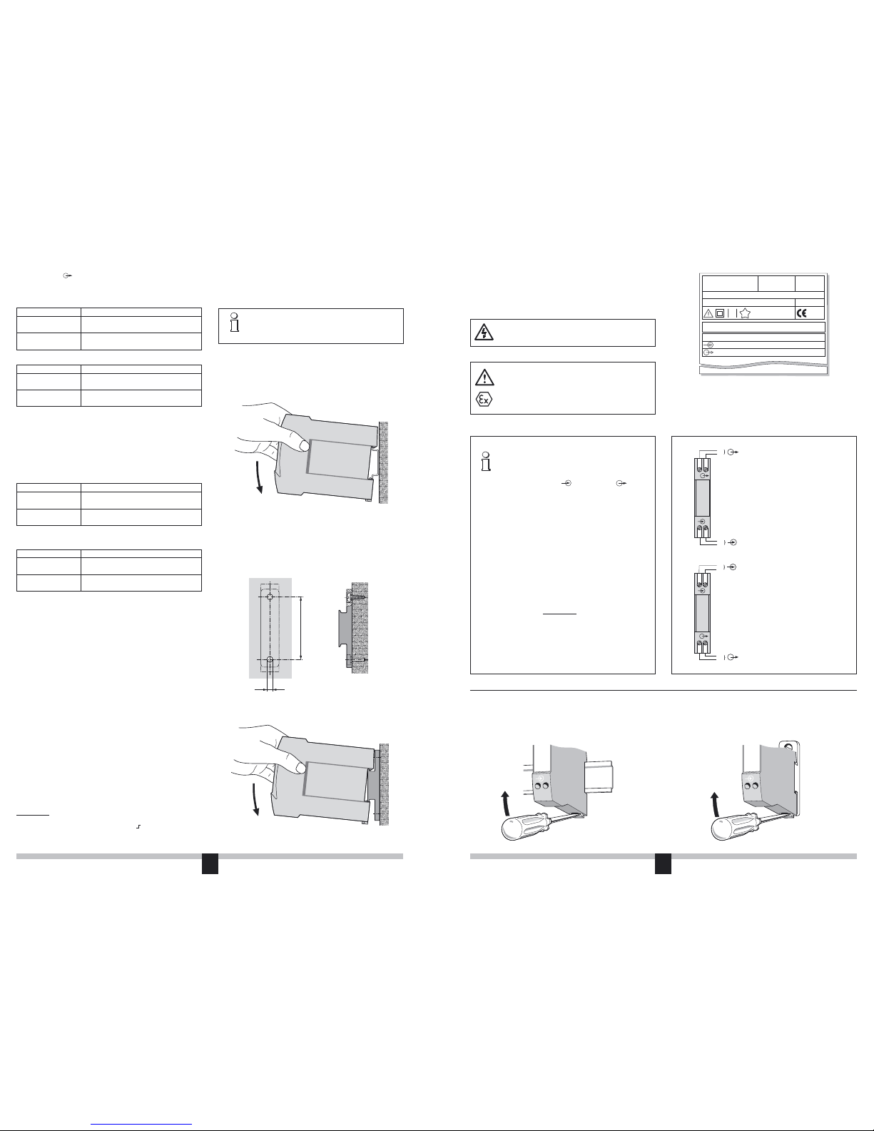
6. Mounting
The SINEAX TI 807 can be mounted either on a top-hat rail or directly
onto a wall or mounting plate using the adapter (standard accessory).
Make sure that the ambient temperature stays within
the permissible limits:
–25 and +55 °C for standard instruments
–20 and +55 °C for instruments in Ex version!
6.1 Top-hat rail mounting
Simply clip the device onto the top-hat rail (EN 50 022) (see Fig. 3).
7. Electrical connections
The electrical connections are made to screw terminals which are easily
accessible from the front of the signal isolator (see Fig. 8 and 9) and can
accommodate wire gauges up to 2.5 mm2.
Make sure that the cables are not live when making
the connections!
In the case of “Intrinsically safe” [EEx ib] IIC or
[EEx ia] IIC explosionproof versions, the supple-
mentary information given on the type examination
certification, the EN 60 079-14 and also local regula-
tions applicable to electrical installations in explosion
hazard areas must be taken into account.
Fig. 6. Mounting on the adapter.
1 This is the time which transpires before the output signal reaches the error limit
of 1% for a step change of the input signal from 0 90%.
2 With current signal and RA = 250 Ω
3 With voltage signal
Fig. 3. Mounting on top-hat rails 35 × 15 or 35 × 7.5 mm.
Connect the input E and output A leads according to Figures 8 and 9.
Signal isolator in housing N17 with one isolation and transmission
channel
Fig. 11Fig. 10
Note that, ...
... the required electrical insulation and transmission
data agree with the data on the nameplate of the
SINEAX TI 807 ( input signal and output
signal, see Fig. 7)!
... in the case of a signal isolator with current outputs
0...20 mA, the total resistance of the external
leads (receiver plus leads) does not exceed the
maximum burden of 1000 Ω (non-Ex version) or
500 Ω (Ex version)! See “Output signal” in Section
5 “Technical data”!
... in the case of a signal isolator with voltage output
0...10 V, the external receiver connected across
the output has a sufficiently high internal resist-
ance RiA in relation to the SINEAX TI 807 output
impedance of 500
Ω! See “Output signal” in Section
5 “Technical data”!
The error due to RiA is:
F [%] =
... the input and output cables should be twisted
pairs and run as far as possible away from heavy
current cables!
4
+
3
–
–
1
+
2
–
+
A
–
+
E
4
+
3
–
–
1
+
2
–
+
A
–
+
E
SINEAX TI 807
Typ: 807-5233
No.: 000000/XXXXXX
Passive DC signal isolator
Passiver DC-Signaltrenner
1997 NLBxxx
Tamb 55 °C
0…20 mA
0…20 mA
0,2
4
Camille Bauer AG
Aargauerstr. 7
CH-5610 Wohlen
Switzerland
Fig. 7. Example of a nameplate.
5.8
60
Fig. 4. Drilling pattern.
6.2 Wall mounting
Drill 2 holes in the wall or panel as shown in the drilling pattern (Fig. 4).
Now secure the adapter (standard accessory) to the wall or panel using
two 5 mm diameter screws (Fig. 5). Clip the device onto the adapter
(Fig. 6).
–
1
+
2
–
1
+
2
8. Commissioning and maintenance
The device is in operation as soon as the input signal E is connected.
The signal isolator requires no maintenance.
Fig. 8.
SINEAX TI 807-511..,
Standard (non-Ex) version
and
SINEAX TI 807-561.. and TI 807-581..,
Ex version
(output signal A “intrinsically safe”)
Fig. 9.
SINEAX TI 807-521.. and TI 807-541..,
Ex version
(input signal E “intrinsically safe”)
Fig. 5. Adapter mounted on wall.
500 [Ω] · 100
RiA [Ω]
9. Releasing the signal isolator
Release the signal isolator from a top-hat rail as shown in Fig. 10 or from
the adapter as shown in Fig. 11.
Other Camille Bauer Power Tools manuals