Camille Bauer SINEAX TI 816 User manual

1
Passive
DC signal isolator
SINEAX TI 816
TI 816-5 Be 996 118-01 09.05
Safety precautions to be strictly observed are marked with
following symbols in the operating instructions:
Camille Bauer LTD
Aargauerstrasse 7
CH-5610 Wohlen/Switzerland
Phone +41 56 618 21 11
Fax +41 56 618 35 35
e-mail: info@camillebauer.com
http://www.camillebauer.com
Operating Instructions
3. Brief description
The signal isolator SINEAX TI 816 serves to electrically insulate an analogue DC
signal in the range 0...20 mA which depending on version is then converted to
a current or voltage signal (0...20 mA or 0...10 V). It does not require a separate
power supply.
The instrument fulfils all the important requirements and regulations concerning
electromagnetic compatibility EMC and Safety (IEC 1010 resp. EN 61 010). It was
developed and is manufactured and tested in strict accordance with the quality
assurance standard ISO 9001.
Contents
1. Read first and then … ................................................................................... 1
2. Scope of supply ............................................................................................. 1
3. Brief description ............................................................................................. 1
4. Versions .......................................................................................................... 1
5. Technical data ................................................................................................ 1
6. Mounting ........................................................................................................ 1
7. Electrical connections .................................................................................... 2
8. Commissioning and maintenance .................................................................. 2
9. Releasing the signal isolator .......................................................................... 2
10. Dimensional drawings .................................................................................... 2
11. Declaration of conformity ............................................................................... 2
1. Read first and then …
The proper and safe operation of the device assumes that the
operating instructions is read carefully and the safety warnings
given in the various Sections
6. Mounting
7. Electrical connections
are observed.
The device should only be handled by appropriately trained
personnel who are familiar with it and authorised to work in
electrical installations.
Unauthorized repair or alteration of the unit invalidates the
warranty!
2. Scope of supply
Signal isolator (Fig. 1)
1 ea. operating instructions (Fig. 2) in English, French, German
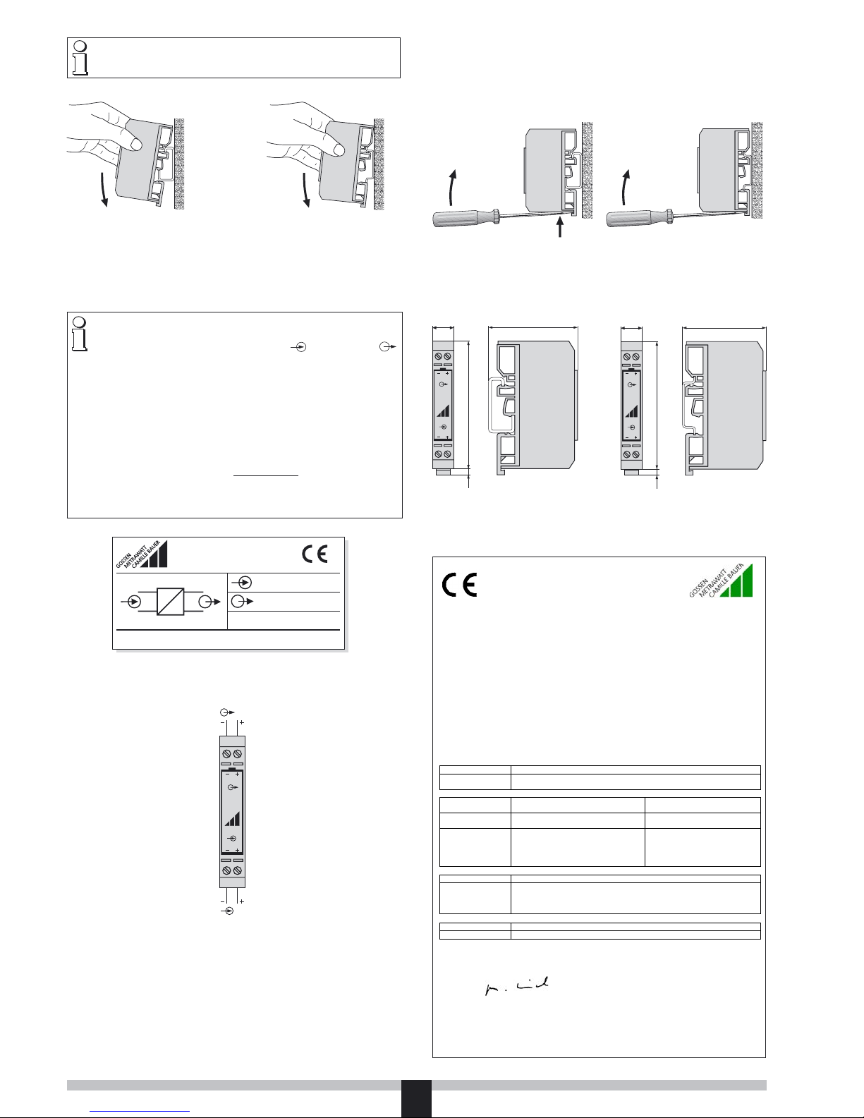
Fig. 1 Fig. 2
1 With current signal 2 With voltage signal
4. Versions
There are two versions of the DC signal isolator SINEAX TI 816 available.
Description Output signal A Order code Order No.
Passive DC signal isolator
input signal E: 0…20 mA,
with 1 isolation and
transmission channel, in
carrying rail housing N12
0…20 mA 816-5110 990 722
0…10 V 816-5111 994 089
5. Technical data
Input signal E
DC current: 0…20 mA
Max. permissible current: 50 mA
Voltage limiter: 18 V ± 5% (with zener diode)
Voltage drop: < 2.1 V (for 500 Ω burden)
Overshoot: < 20 µA (typical 5 µA)
Output signal A
DC current or
DC voltage: 0…20 mA or 0…10 V
Limit: Approx. 30 mA1
Approx. 15 V2
Max. burden: 600 Ω1
Internal resistance: 500 Ω2
Residual ripple: < 20 mV ss
Time constant: Approx. 5 ms
Accuracy data
Error limits: < ± 0,1%1
(reference value 20 mA,
linearity error included)
< ± 0,2%2
(reference value 10 V,
linearity error included)
Ambient conditions
Operating temperature:: –20 to + 65 °C
Storage temperature: –40 to + 85 °C
Annual mean
relative humidity: ≤ 75% Standard climatic rating
Seismic test: 5 g, < 200 Hz, 2 h in each of 3 directions
Shock test: 50 g, 10 shocks in each of 3 directions
Altitude: 2000 m max.
Indoor use statement
6. Mounting
The SINEAX TI 816 isolator is suitable for mounting on two different types of
standard rails:
– onto the G-type rail EN 50 035-G32
or
– onto the top-hat rail EN 50 022-35 ×7.5.
The instruments must only be disposed of in the
correct way!

2
Note “Ambient conditions” in Section “5. Technical data” when de-
termining the place of installation!
Simply clip the signal isolator onto the carrying rail acc. to Fig. 3 or Fig. 4.
Fig. 6. Terminal allocation.
E = Input signal,
A = Output signal.
7. Electrical connections
Easily accessible screw terminals are provided at the front of the signal isolator
(Fig. 6) which accept wire gauges up to 2.5 mm2 (stranded wire) or 4 mm2 (non-
stranded wire).
Note that, …
… the data required to perform the electrical insulation task agree with the
data on the nameplate of the SINEAX TI 816 ( input signal and
output signal, see Fig. 5)!
… in the case of isolators with current outputs 0...20 mA, the total resist-
ance of the external leads (receiver plus leads) does not exceed the max.
burden of 600 Ω! See “output signal”, section “5. Technical data”!
… in the case of isolators with a voltage output 0...10 V, the external receiver
connected across the output has a sufficiently high internal resistance RiA
in relation to the SINEAX TI 816 output impedance of 500 Ω! See “Output
signal” in Section “5. Technical data”!
The error due to RiA is:
F [%] = 500 [Ω] · 100
RiA [Ω]
… that input and output cables should be twisted pairs and run as far as
possible away from heavy current cables!
0...20 mA
0...10 V
99408901
camille bauer 5610 Wohlen Switzerland
Typ 816 – 5111
2(+)
1(–)
4(+)
3(–)
GOSSEN
METRAWATT
CAMILLE BAUER
Fig. 5. Example of a nameplate.
Connect the input and output leads E and A according to Fig. 6.
TI 816
34
12
A
E
Fig. 3. Mounting onto the G-type rail. Fig. 4. Mounting onto the top-hat rail.
8. Commissioning and maintenance
The device is in operation as soon as the input signal E is connected.
The signal isolator requires no maintenance.
TI 816
34
12
12,5
75
4
49,5
TI 816
34
12
12,5
75
4
52
Fig. 9. SINEAX TI 816 on G-type rail
EN 50 035 – G 32.
Fig. 10. SINEAX TI 816 on top-hat rail
EN 50 022 – 35 ×7.5.
9. Releasing the signal isolator
When dismantling the SINEAX TI 816 …
… from G rails proceed according to Fig. 7. Firstly press the signal isolator upwards
(manipulation 1) and tip it upwards at the same time (manipulation 2).
… from top-hat rails proceed according to Fig. 8. Tip the signal isolator up-
wards.
Fig. 7 Fig. 8
10. Dimensional drawings
1
2
11. Declaration of conformity
Diese Erklä rung bescheinigt die Übereinstimm ung mit den T hi s declaration c er t i fi e s compli a n c e wit h th e above ment ione d
gen annt en Ri c h t l i n ien, bei n h a l t e t jedoch k e i n e Zusiche rung directives b ut d o es no t includ e a p r o perty a ssurance.
von Eigenscha ften. Di e Sicherh eitshinwe ise der m itgeliefe rten Th e saf ety n otes g i ven in th e pro d u c t doc u menta t ions , whic h a r e
Produktdokumentationen sind zu beachten. part of the supply, must be observed.
EG - KONFORMITÄTSERKLÄRUNG
DECLARATION OF CONFORMITY
Dokument-Nr./ TI816.DOC
Document.No.:
Hersteller/ Camille Bauer AG
Manufacturer: Switzerland
Anschrift / Aargauerstrasse 7
Address: CH-5610 Woh le n
Produktbezeichnung/ Passiver DC- Sign al trenner
Product name: Pasive DC signal isolator
Typ / Type: SINEAX TI 816
Das bezeichnete Produkt stimmt mit den Vorschriften folgender Europäischer Richtlinien überein,
nachgewiesen durch die Einhaltung folgender Normen:
The above mentioned product has been manufactured according to the regulations of the following
European directives proven through compliance with the following standards:
Nr. / No. Richtlini e / Directive
89/336/EWG
89/336/EEC
Elektromagnetische Verträglichkeit - EMV - Richtlinie
Electromagnetic compa tibility -EM C directive
EMV /
EMC
Fachgrundnorm /
Generic Standard
Messverfahren /
Measurement methods
Störaussendung /
Emission
EN 50 081-2 : 1993 EN 55011 : 1992
Störfestigkeit /
Immunity
EN 50 082-2 : 1994 IEC 1000-4-2 : 1995
IEC 1000-4-3 : 1998
IEC 1000-4-4 : 1995
IEC 1000-4-6 : 1996
Nr. / No. Richtlini e / Directive
73/23/EWG
73/23/EEC
Elektrische Betriebsmittel zur Verwendung innerhalb bestimmter
Spannungsgrenzen - Niederspannungsrichtlinie - CE-Kennzeichnung : 95
Electri cal equipment for use within certain voltage limits - Low Voltage
Directive - A ttac hmen t of CE mark : 95
EN/Norm/Standard IEC/Norm/Standard
EN 61 010-1 : 1993 IEC 1010-1 : 1990 + A1 : 1992
Ort, Datum /
Place, date: Wohlen, den 4. November 1999
Unterschrift / M.U lrich
Signature: Leiter Entwicklung
Table of contents
Other Camille Bauer Power Tools manuals