5 6
Step 15.
Set the aluminum threshold (13) on the
shower tray. Adjust the width and use the
screws (20) tp secure each end to the
pivot bracket. Use the Allen key (part T-1) to
secure the aluminum threshold.
You may use the plastic wedges supplied
(part T-3) if the base is not perfect plumbed.
Step 16.
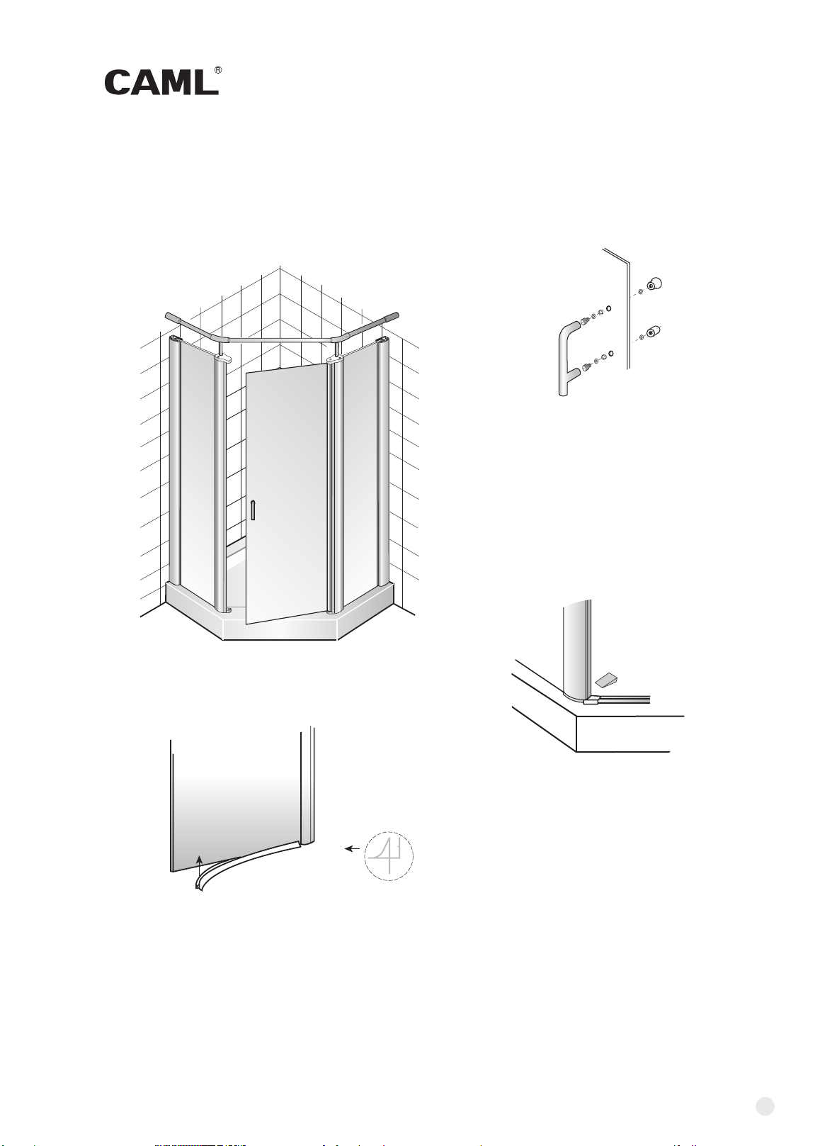
Push and tap the plastic water guard (12)
on the bottom of the glass for water sealing.
To the
inside
Install the handle in the door, using the
approiate washers and bushings
supplied (14).
Step 14.
Step 11.
Place cover bracket (5) in the support rod
on the top of catching post and secure it
with screws (28).
Step 9.
Set the bottom of the pivot door
in the hole of the bottom pivot bracket,
using the pivot bushing (21).
This pivot bracket is preassembled.
Step 13.
Secure the top support bars with
Allen key supplied (part T-2).
Step 10.
Put the top pivot bracket with a hole (6) all the way
down over the support rod and secure it with
screws (28).
ST3.9x25
5/32
"×1"
ST3.9x25
5/32
"×1"
Remark: If you want to change right door to
left door installation,
both fixed panels should be exchanged with
180 rotation (top to bottom).
Step 12.
Install the top support bars with two of 135 degree connecting
tubes. You may need to cut the bars and adjust their positions
to set the door in place.