1
RF401 Series Spread Spectrum Data
Radio/Modems
1. Introduction
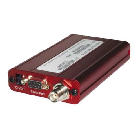
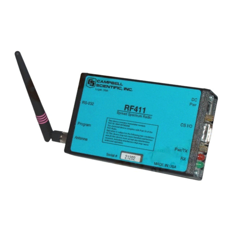
This manual discusses the RF401, RF411, and RF416 spread spectrum radios.
These radios differ from one another primarily in the radio frequencies at
which they communicate. Most of the information provided in this manual is
also relevant for our RF400, RF410, and RF415 radios that were retired in May
2005. For simplicity sake, throughout the manual the term “RF401” will refer
to the RF401, RF411, and RF416 radios, unless specified otherwise, and the
term “RF400” will refer to the RF400, RF410, and RF415 radios.
The RF401 is a 900 MHz, frequency hopping, spread spectrum, data
radio/modem for point-to-point and point-to-multipoint communications. An
excellent receiver combined with 100 mW transmitter power make possible,
depending on path specifics, communication distances of 1/4 to 5 miles using
omni-directional antennas and 10 to 20 miles using 9 dBd directional antennas
(see Appendix H for a discussion of antenna gain and other factors affecting
distance).
The RF411 differs from the RF401 in that it operates at 922 MHz for regions
such as Australia, New Zealand, and Israel. The RF411’s communication
range is the same as that of the RF401.
The RF416 is a 2.4 GHz version with 50 mW transmitter intended mainly for
certain European and Asian markets. Communication distances vary from 300
feet (indoors) to ¼ mile (100 to 400 meters) with omni-directional antennas to
over 12 miles (19 kilometers) with gain antennas and optimal terrain.
Users do not normally need a communications authority license for the RF401
series configurations described in this manual including U.S. Government
Agencies regulated by NTIA Annex K. The 900 MHz and 2.4 GHz bands are
shared with other non-licensed services such as cordless telephones and with
licensed services including emergency, broadcast, and air-traffic control, so
band usage will vary from location to location as will man-made noise. Spread
spectrum technology resists noise and interference; however, the user may
wish to test communications on site using Quick Start (Section 3) before
committing to its use.
The RF401 operates from a 12 VDC power supply. The RF401’s low standby
current modes allow it to operate at remote sites on small power budgets.
The RF401 was designed for ease of installation. It works in many
applications “out of the box” with default settings.
