camping first Satmex Flat User manual

Satmex Flat
Bedienungsanleitung

1. Einführung
1.1 Sicherheitshinweise................................................................................03
1.2 Kurzbeschreibung....................................................................................03
1.3 Lieferumfang...............................................................................................03
1.4 Systemkomponenten............................................................................04
2. Installation
2.1 Antenne in den Installations-Modus setzen............................ 05
2.2 Installation auf dem Dach................................................................... 06
2.3 Klebeanleitung...........................................................................................06
2.4 Installation im Innenbereich .............................................................08
2.5 Anschluss der Komponenten...........................................................09
3. Steuergerät
3.1 Frontansicht.................................................................................................10
3.2 Rückansicht..................................................................................................10
4. Satellitenübertragung ...............................................................................11
5. Inbetriebnahme und Bedienung....................................................... 12
6. Fehlerbehebung ..............................................................................................13
7. Ausleuchtzone................................................................................................... 14
8. Montageabmessungen..............................................................................15
9. Aktualisierung der Firmware................................................................ 16
10. Technische Daten.........................................................................................17
Inhaltsverzeichnis
02 03
1. Einführung
DEUTSCH DEUTSCH
1.1 Sicherheitshinweise
1.2 Kurzbeschreibung
1.3 Lieferumfang
Vorsicht: Unsachgemäße Handhabung kann zu schweren Schäden an die-
sem Gerät führen. Die Verantwortlichen können auch für daraus resultierende
weitere Schäden am Gerät verantwortlich gemacht werden.
Hinweis: Lesen Sie das Benutzerhandbuch sorgfältig durch bevor Sie mit der
Installation beginnen. Falls Sie schon ähnliche Produkte installiert haben, muss
die Vorgehensweise mit diesem Produkt nicht übereinstimmen.
Dieses Gerät ist eine der innovativsten und technologisch fortschrittlichsten Satelliten-
positionierungsanlagen. Die Antenne verfügt über eine einzigartige Kombination von
modernsten Komponenten. Vollen Komfort bietet die schnelle Satellitensuche und eine
Kompatibilität mit allen digitalen Satellitenreceivern und Fernsehgeräten.
• Antenne (Haupteinheit)
• Steuergerät inkl. Stromkabel
• 1x Antennenanschlusskabel (10 m)
• 1x Antennenanschlusskabel (1 m)
• Bedienungsanleitung

1. Verbinden Sie das mitgelieferte Antennenkabel (10m) mit der Antenne und dem
Steuergerät.
2. Schließen Sie das mitgelieferte Stromkabel an eine Stromquelle (12-24V, mind. 5A) an
und verbinden es mit dem Steuergerät.
3. Schalten Sie das Steuergerät am Netzschalter ein und warten, bis der Bootvorgang
abgeschlossen ist.
4. Leuchten alle LEDs im Display (Checking...) und die Antenne beginnt nach einem Sa-
telliten zu suchen, drücken Sie umgehend die Bestätigungstaste .
5. Die Antenne bewegt sich nun in den In-
stallations-Modus und stellt sich aufrecht
nach oben.
6. Lösen Sie die vier Inbusschrauben um die
Antenneneinheit von der Montageplatte
zu heben.
7. Drücken Sie die STOW-Taste um die
Antenne wieder einzufahren.
8. Entfernen Sie alle Anschlusskabel um mit
der Installation zu beginnen.
1.4 Systemkomponenten
2.1 Antenne in den Installations-Modus setzen
1. Einführung 2. Installation
04 05DEUTSCH DEUTSCH
Antenneneinheit
Die Hochleistungsantenne und der Elevationswinkel von 0-90°
ermöglicht bestmöglichen Empfang in ganz Europa.
Steuergerät
Das Steuergerät dient zur Satellitenauswahl und Steuerung. Es
wird zwischen Antenne und Receiver geschaltet und versorgt
die Antenne mit Strom.
Hinweis:
Die Antenne besitzt zusätzlich einen weiteren Anschluss für einen zweiten
Receiver. Für den korrekten Anschluss der Komponenten beachten Sie bitte das
Anschlussdiagramm auf Seite 9.
Öffnen Sie den Karton und entnehmen Sie das Steuergerät, die Anschlusskabel und das
Verpackungsmaterial. Heben Sie die Antenne gerade nach oben aus dem Karton. Stellen
Sie die Anlage niemals auf den Kopf!
Achtung: Beachten Sie bitte auch, dass sich durch die Antenne die Fahrzeug-
höhe entsprechend ändert! Bitte halten Sie sich unbedingt an die einzelnen
Punkte der Montageanweisung!
Allgemeines:
Sorgen Sie für einen geeigneten Arbeitsplatz, eine Garage/Halle ist besser als ein Platz im
Freien. Die Umgebungstemperatur zur Montage soll zwischen +5° C und max. +25°C
liegen. Arbeiten Sie nicht direkt in der Sonne. Halten Sie die Arbeitsvorschriften beim
Umgang mit Chemieprodukten ein. Sorgen Sie für die notwendige Arbeitshygiene.
Grundsätzlich empfehlen wir den Einbau durch Ihren Fachhändler oder eine Fachwerk-
statt vornehmen zu lassen!
Um die Antenne von der Montageplatte zu lösen, empfehlen wir, die Antenne in den In-
stallationsmodus zu setzen, um die vier Inbusschrauben besser lösen zu können. Hierzu
müssen Sie die Antenne und das Steuergerät zunächst provisorisch verbinden.

2. Installation
06 07DEUTSCH DEUTSCH
2. Installation
1. Bereiten Sie den Kleber für die Montage vor.
2. Tragen Sie nun den Kleber auf die angezeich-
nete Fläche in Schlangenlinien auf, damit der
Kleber bis ins Innere gut aushärten kann.
3. Setzen Sie nun sofort (innerhalb von 5 Minuten nach Kleberauftrag) die Montage-
platte auf das angezeichnete Feld. Drücken Sie sie leicht und gleichmäßig an. Es
müssen sich nach dem Andrücken noch mindestens 2 mm Kleber zwischen Montage-
platte und Oberfläche befinden. Der Kleber ist nach max. 48 Stunden bei +18° C und
einer relativen Luftfeuchte von 50% ausgehärtet. Sollte während der Montagezeit eine
geringe Luftfeuchtigkeit herrschen, sprühen Sie nach dem Verkleben in der Umge-
bung der Antenne immer wieder etwas Wasser in die Luft.
2.3 Klebeanleitung
1. Vergewissern Sie sich, dass das Dach Ihres Fahrzeugs ausreichend stabil ist. Bei
ungenügender oder zweifelhafter Dachstabilität ist ein ca. 2mm starkes Blech mit
ca. 100x100 cm auf der Dachaußenhaut zu befestigen. Erkundigen Sie sich dazu bei
Ihrem Fahrzeughersteller.
2. Prüfen Sie, ob alle Teile vorhanden sind.
3. Setzen Sie die Montageplatte auf den späteren Montageplatz. Achten Sie darauf, dass
die Montagefläche eben ist und keine Dachaufbauten im Weg sind. Beachten Sie
unbedingt die Montageabmessungen auf Seite 15. Der mindeste Abstand zu einer
Klimaanlage sollte 30 cm betragen.
4. Säubern Sie die Montagefläche mit einem
geeigneten Reiniger und einem Vliestuch
um Schmutz und Unreinheiten zu entfernen.
Zeichnen Sie anschließend die Grundplatte
der Antenne mit einem Stift an.
5. Rauen Sie die gezeichnete Fläche mit Schleifpapier (120er Körnung) leicht an und
säubern Sie die Fläche erneut mit dem Reiniger (ACHTUNG: Fläche anschließend
nicht mehr berühren) und lassen Sie den Reiniger ca. 10 Minuten ablüften.
2.2 Installation auf dem Dach 4. Entfernen Sie die evtl. ausgetretene Klebemasse sofort mit einer Spachtel o. ä. und
säubern Sie die verunreinigten Flächen mit dem Reiniger und einem Vliestuch.
5. Nach der kompletten Montage und Aushärtung des Klebers, kann eine Silikonfuge
um die Montageplatte gezogen werden.
Wichtig:
Die Antenne muss mit der Motoreinheit in Fahrtrichtung zeigen!
Wichtig:
Verkleben Sie nicht die Anschluss-
buchse der F-Stecker mit dem Dach.
Im Servicefall kann die Antenne nicht
mehr vom Dach demonitert werden!
Fahrtrichtung
6. Setzen Sie anschließend die Antenne auf
die Montageplatte und befestigen diese
wieder mit den vier Inbusschrauben.

08 09DEUTSCH DEUTSCH
2. Installation
2.5 Anschluss der Komponenten
Steuergerät
(+)(-)
Zündungsplus
Stromversorgung
Die Antenne fährt automatisch in den eingefahrenen Zustand, sobald der Zündschlüssel
gedreht wird. Diese Funktion steht nur zur Verfügung, wenn die Kabel 4und 5ange-
klemmt sind. Sobald die Antenne eingefahren ist, leuchten am Steuergerät die LEDs der
Satelliten nacheinander auf.
DC 12-24V über Batterie (Pluspol
Dauerversorgung ROT) oder optio-
nales 230V / 12V DC Netzteil (Keine
Ladegeräte). Achten Sie darauf, dass
eine Stromstärke von mind. 5 Ampe-
re gewährleistet ist.
(+) (-)
1
Koaxialkabel 10 m
Pluspol
Koaxialkabel 1 m
Minuspol
Zündungsplus
1
2
3
4
5
2
3
4
4
5Zweiter Anschluss
(optional)
Nicht im
Lieferumfang
enthalten!
F-Anschluss
mit der Bezeichnung:
CONTROL-BOX
F-Anschluss
mit der Bezeichnung:
RECEIVER
Achtung:
Schließen Sie das Gerät immer über eine
mit 7 Ampere abgesicherte, und mind.
2,5 mm² starke Leitung an (niemals
direkt an die Batterie des Fahrzeuges).
Fernseher Fernseher
2. Installation
1. Das Koaxialkabel wird im Inneren des Fahrzeuges verlegt.
2. Vergewissern Sie sich bei der Wahl des Standortes für das Steuergerät und den
Sat-Receiver, dass beide Geräte an einem trockenen und geschützten Ort stehen.
3. Das Steuergerät und den Sat-Receiver nicht in die Nähe von Wärmequellen stellen
und für ausreichend Belüftung sorgen.
4. Im Folgenden werden die grundlegenden Anschlussmöglichkeiten für die Anten-
nenanlage gezeigt:
• Verbinden Sie die Stromversorgung (rot-schwarzes Kabel) für das Steuergerät mit
Ihrer Batterie des Fahrzeuges über eine Sicherung (7 Ampere), um einen Kabel-
brand bei Kurzschluss zu vermeiden. Das gelbe Kabel wird an dem Zündungsplus
des Fahrzeuges angeschlossen und ebenfalls mit einer Sicherung von 7 Ampere
abgesichert (Dieses Kabel muss nur angeschlossen werden, wenn die Antenne au-
tomatisch bei Motorstart einfahren soll.). Das übrig bleibende schwarze Kabel wird
an den dazugehörigen Minuspol der Zündungsanlage (Masse) angeschlossen.
• Verbinden Sie das Kabel, dass von der Antenne kommt, mit dem Steuergerät:
- 10m Koaxialkabel mit F-Stecker in„ANTENNA“
• Verbinden Sie das Steuergerät mit dem Sat-Receiver:
- 1m Koaxialkabel mit F-Stecker von„RECEIVER“ zum Sat-Receiver
2.4 Installation im Innenbereich
Hinweis:
Möchten Sie zwei Fernseher betreiben, schließen Sie ein zweites Koaxialkabel
von der Antenne direkt an den zweiten Sat-Receiver an.

10 11DEUTSCH DEUTSCH
Schlechtes Empfangssignal
4. Satellitenübertragung
Gutes Empfangssignal
Direct Broadcast Service (DBS) strahlt Audio, Video und Daten über den Satelliten aus,
der sich in ca. 35.000km Höhe über der Erde befindet. Mit einer Empfangsstation wie die
Antenne und einem Satelliten Receiver werden die Signale vom Satelliten empfangen
und verarbeitet. Das System erfordert eine klare Sicht auf den Satelliten, um den Signa-
lempfang maximal auszunutzen.
Objekte wie Bäume, Brücken und große Häuser, die sich im Einfallswinkel des Satelliten
befinden, führen zu einem Verlust des Signals. Starker Regen, Wolken, Schnee oder Eis
kann die Empfangsqualität beeinträchtigen. Wenn das Satellitensignal durch schwere
Wetterbedingungen verloren geht, wird das laufende Programm des Receivers beendet
(das Bild wird einfrieren, bzw. verschwinden). Wenn die Witterungsverhältnisse wieder
einen guten Empfang ermöglichen, wird das TV Bild wieder hergestellt.
3. Das Steuergerät
3.1 Frontansicht
3.2 Rückansicht
USB Anschluss zur
Aktualisierung der Firmware
Hauptschalter Display Satellitenauswahl
(hoch / runter) Bestätigung
GrundpositionLED Anzeigen
(PWR = Power)
(SEARCH = Suche)
(STOW = Keine Funktion)
(ERR = Fehlfunktion)
Anschluss
zur Antenne
Anschluss am TV
(Receiver) Anschluss
Service Stromversorgung
12-24V (5A)

12 13DEUTSCH DEUTSCH
6. Fehlerbehebung
Kein Satellitensignal
Objekte wie Bäume, Brücken und große Häuser, die sich im Einfallswinkel des Satelli-
ten befinden, führen zu einem Verlust des Signals.
Wenn das Satellitensignal durch schwere Wetterbedingungen verloren geht, wird das
laufende Programm des Receivers beendet (das Bild wird einfrieren, bzw. verschwin-
den). Wenn die Witterungsverhältnisse wieder einen guten Empfang ermöglichen,
wird das TV Bild wieder hergestellt.
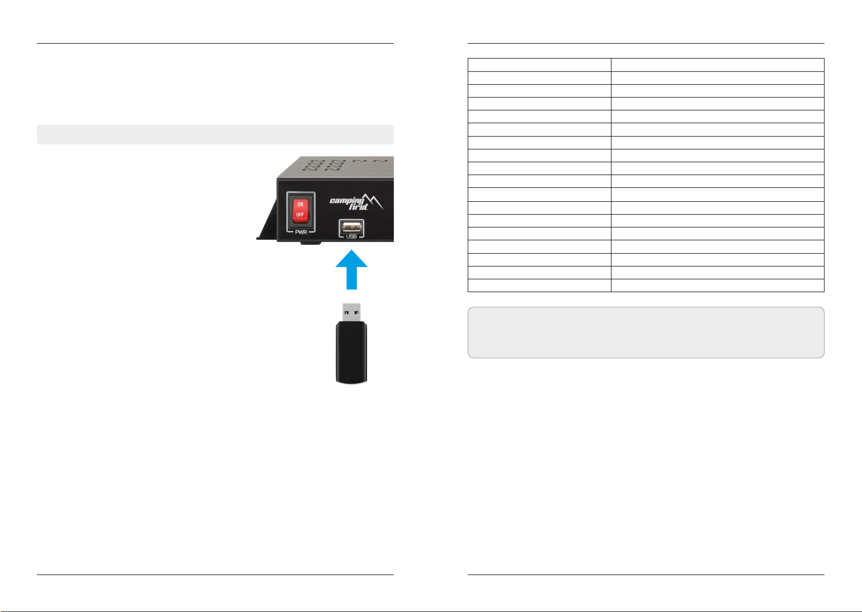
Display Anzeigen am Steuergerät
Antenna (FAIL)
Es besteht keine Verbindung zur Antenne, oder es gibt Kommunikationsschwierig-
keiten mit der Antenne. Überprüfen Sie ggf. die Koaxialleitung.
Tuner (FAIL)
Es gibt Probleme mit dem Tunereingang des Steuergerätes. Bitte suchen Sie einen
Fachhändler zur Überprüfung auf.
Button (FAIL)
Es gibt Probleme mit dem Mainboard (Hauptplatine des Steuergerätes. Bitte suchen
Sie einen Fachhändler zur Überprüfung auf.
Gibt es Verschmutzung auf der Antenne?
Starke Verschmutzung auf dem Spiegel kann zu Empfangsproblemen führen.
Ist alles richtig angeschlossen und eingeschaltet?
Vergewissern Sie sich, dass der TV und der Receiver richtig angeschlossen und der
Receiver für den Satellitenempfang richtig eingestellt ist. Sind alle Kabel richtig an-
geschlossen oder hat die Verbindungen eine andere Person versehentlich gelockert?
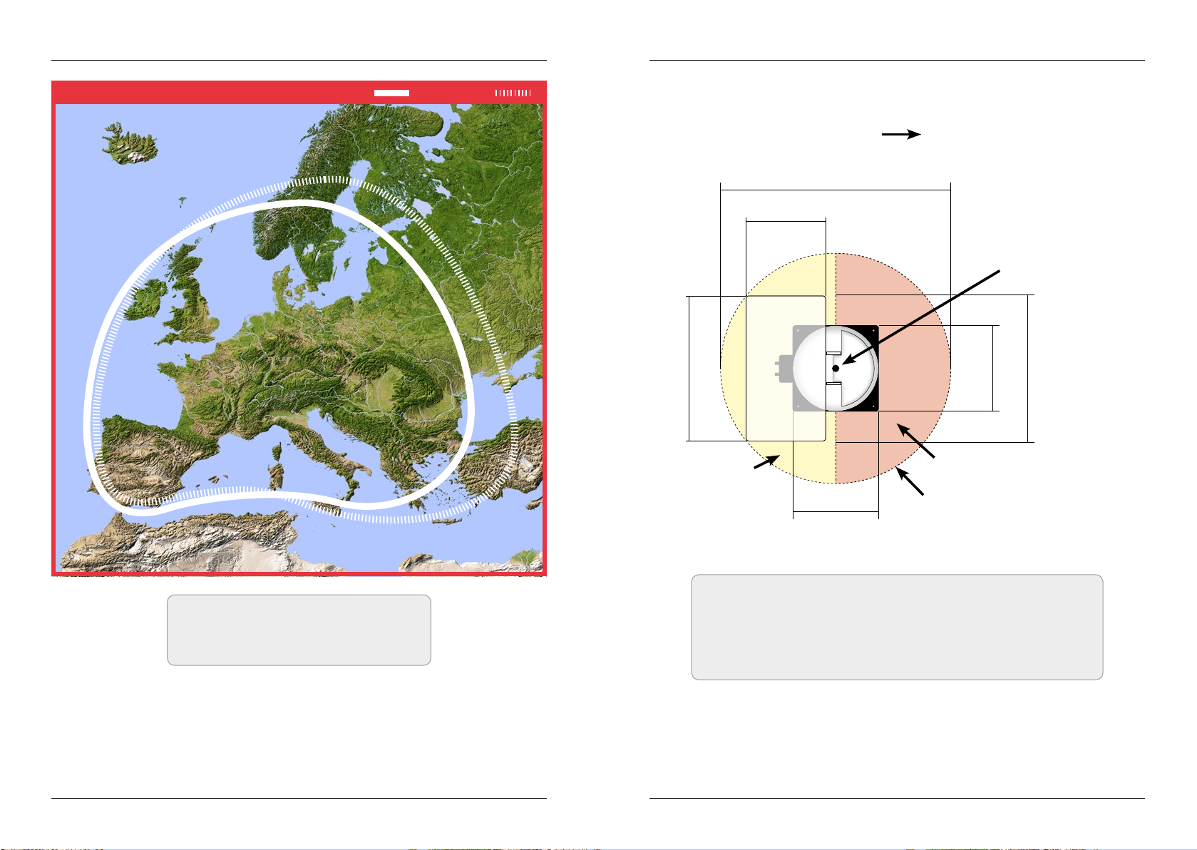
Satelliten Ausleuchtzone
Satelliten sind in festen Positionen über dem Äquator im Orbit positioniert. Um die TV
Signale zu empfangen, muss der Empfangsort innerhalb der Ausleuchtzone liegen.
Überprüfen Sie an Hand der Grafik, ob sich Ihr Standort in der Ausleuchtzone des
Satelliten befindet. In den Randgebieten der Ausleuchtzone kann es zu Empfangsstö-
rungen kommen.
Satellitenfrequenz wurde geändert
Fernsehsender wechseln vereinzelt Ihre Frequenz die mit der Frequenz im Receiver
dann nicht mehr übereinstimmt. Erkundigen Sie sich nach der aktuellen Frequenz des
Senders.
5. Inbetriebnahme und Bedienung
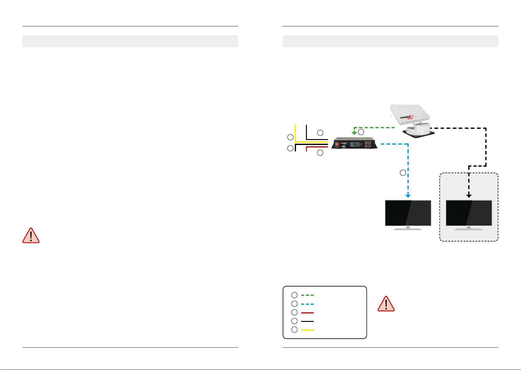
1. Schalten Sie das Steuergerät am Hauptschalter ein. Die grüne LED-Anzeige (PWR) am
Steuergerät leuchtet auf - der Bootvorgang startet.
2. Nach dem Bootvorgang werden die vorinstallierten Satelliten im Display angezeigt.
Wählen Sie innerhalb von 2 Sekunden den gewünschten Satelliten mit den Satel-
litenauswahltasten (hoch/runter).
3. Das Steuergerät prüft nun, ob alle Komponenten
verbunden sind und das System betriebsbereit
ist. Sollte das Steuergerät einen Fehler finden,
erscheint im Display „FAIL“ hinter dem jeweiligen
Punkt und die rote LED-Anzeige (ERR) leuchtet
durchgehend. Ist alles mit OK bestätigt startet nun
der Suchvorgang. Während dem Suchvorgang
blinkt die gelbe LED-Anzeige (SEARCH).
4. Nach erfolgreicher Suche zeigt das Steuergerät die Satellitenliste im Display, die gelbe
LED-Anzeige erlischt und das Display wird abgedunkelt. Um Strom zu sparen, können
Sie das Steuergerät am Netzschalter ausschalten.
5. Wenn Sie die Antenne wieder einfahren möchten, schalten Sie das Steuergerät ein
und drücken die STOW Taste.
Hinweis:
Um den Satelliten zu wechseln, können Sie mit den Satellitenauswahltasten (hoch/
runter) einen beliebigen wählen. Das Steuergerät beginnt erneut die Suche.

14 15DEUTSCH DEUTSCH
7. Ausleuchtzone 8. Montageabmessungen
Hinweis:
In den Randgebieten der Ausleuchtzone
kann es zu Empfangsstörungen kommen.
Hinweis:
Direkt an der Vorderseite der Antenne können Aufbauten mit einer
Höhe von max. 14cm vorhanden sein, ohne die Rotation der Emp-
fangseinheit zu stören (siehe roter Bereich der Grafik). Im gelben
Bereich dürfen keine Aufbauten vorhanden sein.
Fahrtrichtung
29 cm
31 cm max. Schwenkbereich
Aufbauten bis max. 14 cmKeine
Aufbauten
83 cm
31 cm
52,5 cm
53 cm
Drehpunkt
Astra Hotbird
Empfangsreichweite

16 17DEUTSCH DEUTSCH
9. Aktualisierung der Firmware 10. Technische Daten
Konformitätsinformation
Hiermit erklärt die Firma New Line Trading UG (haftungsbeschränkt), dass sich folgendes
Gerät in Übereinstimmung mit den grundlegenden Anforderungen und den übrigen
einschlägigen Bestimmungen der Richtlinien 2014/30/EU (EMV), 2014/35/EU (LVD) und
2014/53/EU (RED) befindet:
Camping rst Satmex Flat (Artikel-Nr. 600103)
Die Konformitätserklärung zu diesem Produkt liegt der Firma vor:
New Line Trading UG (haftungsbeschränkt)
Nelkenweg 23
D-98617 Obermaßfeld-Grimmenthal
Die Konformitätserklärung können Sie auf unserer Homepage downloaden:
www.camping-first.de/support/downloads
Updatevorgang
Von Zeit zu Zeit kommt es vor, dass die Firmware des Steuergerätes aktualisiert werden
muss (z.B. bei einer Frequenzänderung des Satellitenbetreibers oder einer allgemeinen
Verbesserung des Steuergeräts).
Die aktuelle Firmware finden Sie auf unserer Homepage www.camping-rst.de
1. Kopieren Sie die Firmware-Datei auf einen ge-
eigneten USB Stick. Der USB Stick sollte auf
FAT32 formatiert sein und keine anderen Datei-
en beinhalten.
2. Vergewissern Sie sich, dass das Steuergerät am
Hauptschalter ausgeschaltet ist.
3. Stecken Sie den USB Stick mit der neuen Firm-
ware in die USB Buchse an der Vorderseite.
4. Schalten Sie nun das Steuergerät ein. Das Steu-
ergerät bootet und startet den Updatevorgang
automatisch. WICHTIG: Schalten Sie das
Steuergerät während dem Updatevorgang
nicht aus, um evtl. Schäden zu vermeiden!
5. Nach erfolgreichem Update schaltet sich das
Steuergerät aus und startet automatisch neu.
Der Updatevorgang ist nun beendet. Die aktu-
elle Firmware wird kurz nach dem Bootvorgang
im Display angezeigt.
Hinweis:
Gewicht und Abmessungen sind nicht die absolut exakten Werte.Technische Daten
können ohne vorherige Ankündigung jederzeit geändert werden.
Antennen Typ Flachantenne
Anzahl der Teilnehmer 2
LNB Typ Universal LNB
Frequenzband Ku Band
Frequenzbereich 10.7GHz bis 12.75 GHz
LNB Verstärkung 33dBi
Empfangsleistung 49dBW
Polarisation V/H
Motorsteuerung 2-Achsen DC Motor
Neigungswinkel 0° bis 90°
Suchwinkel 365°
Auto Skew ja
Temperaturbereich -20° C bis +60° C
Spannungsversorgung 12V DC @ 3Ampere
Gewicht 7 kg
Abmessungen Empfangseinheit 525 x 290mm (B/H)
Abmessungen Antenne 525 x 150 x 480mm (L/B/H)
Abmessungen Steuergerät 200 x 45 x 134 mm (B/H/T)

Version 1.2
New Line Trading UG (haftungsbeschränkt)
Nelkenweg 23
D-98617 Obermaßfeld-Grimmenthal
Technische Änderungen,
Druckfehler und Irrtümer vorbehalten.
Satmex Flat
user manual

1. Introduction
1.1 Safety information ...................................................................................03
1.2 Short discription........................................................................................03
1.3 Delivery........................................................................................................... 03
1.4 System components.............................................................................. 04
2. Installation
2.1 Set the antenna to installation mode.......................................... 05
2.2 Installation on the roof..........................................................................06
2.3 Gluing instructions.................................................................................. 06
2.4 Indoor installation....................................................................................08
2.5 Connecting the components...........................................................09
3. Control unit
3.1 Front view ..................................................................................................... 10
3.2 Rear view ....................................................................................................... 10
4. Satellite transmission..................................................................................11
5. Startup and operation................................................................................12
6. Troubleshooting ..............................................................................................13
7. Foot print ...............................................................................................................14
8. Mounting Dimensions................................................................................15
9. Firmware Update.............................................................................................16
10. Specications..................................................................................................17
Content
02 03
1. Introduction
ENGLISH ENGLISH
1.1 Safety information
1.2 Short discription
1.3 Delivery
Warning: Improper handling by unqualified personnel can cause serious da-
mage to this equipment. Unqualified personnel who tamper with this equip-
ment may be held liable for any resultant damage to the equipment.
Note: Before you begin, carefully read each of the procedures in this manual. If
you have not performed similar operations on comparable equipment, do not
attempt to perform these procedures.
The satellite antenna system is the most innovative and most technologically advanced
satellite Positioner system. The antenna has a unique combination of cutting-edge com-
ponents. Fast satellite search and compatibility with all digital, HD-ready set-top boxes
and TV sets are guaranteed.
• Antenna (Main unit)
• Control unit incl. power cable
• 1x antenna cable (10 m)
• 1x antenna cable (1 m)
• User manual

1.4 System components 2.1 Installation on the roof
1. Introduction 2. Installation
04 05ENGLISH ENGLISH
Antenna unit
The high-gain antenna and the elevation angle of 0-90° allows
optimum reception throughout Europe.
Control unit
The control unit is used for satellite selection and control. It is
connected between the antenna and the set-top box and sup-
plied the antenna with electricity.
Note:
The antenna also has another connection for a second set-top box. For the cor-
rect connection of the components, refer to the wiring diagram on page 9.
Open the box and remove the control unit, cables and packing material. Lift the antenna
straight up out of the box. Never place the system upside down. When you lay down the
antenne, make sure that the cable attached to the antenna not be below the base plate
to prevent damages. Warning: Please also note that the antenna will change the height of the
vehicle will change accordingly! Please strictly adhere to the various points in
the installation instructions!
Basically, we recommend that you leave the installation to do by your dealer or workshop!
1. Connect the supplied antenna cable (10 m) to the antenna and the control unit.
2. Connect the supplied power cord to a power source (12-24V, mind. 5 A) and connect
it to the control unit.
3. Turn on the control unit at the power switch and wait for the boot process.
4. If all the LEDs in the display are flashing (Checking...) and the antenna is starting to
search for a satellite, press the confirmation button immediately.
5. The antenna now moves into installation mode and stands upright.
6. Loosen the four allen screws to lift the antenna unit off the mounting plate.
7. Now you can retract the antenna by pressing the STOW button .
8. Remove all connection cables to start the installation.
2.1 Set the antenna to installation mode
In order to release the antenna from the mounting plate, we recommend placing the
antenna in installation mode to better loosen the four Allen screws. To do this, you must
first provisionally connect the antenna and the control unit.

2. Installation
06 07ENGLISH ENGLISH
2. Installation
1. Prepare the adhesive for assembly.
2. Now apply the glue on the marked surface in
serpentine lines, so that the glue can harden
well inside.
3. Immediately place the mounting plate on the marked field (within 5 minutes after
application of the adhesive). Press lightly and evenly. After pressing, there must be
at least 2 mm of glue between the mounting plate and the surface. The glue is after
max. Hardened for 48 hours at + 18 ° C and a relative humidity of 50%. If there is low
humidity during the assembly time, after spraying in the area surrounding the anten-
na, always spray some water into the air.
2.3 Gluing instructions
1. Make sure that the roof of your vehicle is sufficiently stable. In the case of insufficient
or doubtful roof stability, a sheet of approx. 2 mm thick with approx. 100 x 100 cm
must be fastened to the roof outer skin. Inquire with your vehicle manufacturer.
2. Check if all parts are present.
3. Place the mounting plate on the later mounting place. Make sure that the mounting
surface is flat and no roof structures are in the way. Please note the mounting dimen-
sions on page 15. The minimum distance to an air conditioner should be 30 cm.
4. Clean the mounting surface with a suitable cleaner and a non-woven cloth to remove
dirt and impurities. Then draw the base of the
antenna with a pen.
5. Lightly roughen the drawn area with 120 grit
sandpaper and clean the surface again with
the cleaner (CAUTION: do not touch the sur-
face afterwards) and allow the cleaner to air
for approx. 10 minutes.
2.2 Installation on the roof 4. Immediately remove any leaked adhesive with a spatula or similar and clean the
contaminated surfaces with the cleaner and a nonwoven cloth.
5. After complete installation and desiccation of the adhesive, a silicone joint can be
pulled around the antenna base.
Important:
The antenna must point with the motor unit in the direction of travel!
Important:
Do not glue the connection socket
of the F-plug with the roof. In case of
service, the antenna can no longer be
removed from the roof!
direction of travel
6. Then place the antenna on the moun-
ting plate and fasten it again with the
four Allen screws.

08 09ENGLISH ENGLISH
2. Installation 2. Installation
2.5 Connecting the components
Plus ignition
Power supply:
The antenna automatically moves to the retracted position when the ignition key is
turned. This function is only available when the cable 4and 5are connected. Once the
antenna is retracted, the LEDs light up on the control unit of the satellites in succession.
12-24V DC via battery (positive-per-
manent systems) or optional DC po-
wer supply 230V/12V (no charger).
Ensure that a current is assured of at
least 5 amps.
Coax cable 10 m
Positive pole
Coax cable 1m
Negative pole
Plus ignition
1
2
3
4
5
Warning:
Connect the device only at a 7 amp
protected line. The line must be at least
2.5 mm² strong. (never directly to the car
battery).
Control unit
(+)(-)
TV
(+) (-)
1
2
3
4
4
5
TV
not in
Included!
Second connection
(optional)
1. The coaxial cable is routed inside the vehicle.
2. When choosing the location for the controller and the satellite receiver, make sure
that both units are in a dry and sheltered place.
3. Keep the controller and the satellite receiver away from heat sources and provide
adequate ventilation.
4. The basic connection options for the antenna system are shown below:
• Connect the power supply (red-black wire) for the controller to your vehicle‘s
battery via a fuse (7 amps) to prevent cable burn in the event of a short circuit. The
yellow cable is connected to the ignition plus of the vehicle and also secured with
a fuse of 7 amps (this cable only needs to be connected if the antenna is to start
automatically when the engine is started.). The remaining black cable is connected
to the corresponding negative pole of the ignition system (ground).
• Connect the cable coming from the antenna to the controller:
- 10 m coaxial cable with F-connector in„ANTENNA“
• Connect the controller to the satellite receiver:
- 1 m coaxial cable with F connector from„RECEIVER“ to the satellite receiver
2.4 Indoor installation
Note:
If you want to operate two televisions, connect a second coaxial cable from the
antenna directly to the second satellite receiver.
F-connector
with description:
CONTROL-BOX
F-connector
with description:
RECEIVER

10 11ENGLISH ENGLISH
3. Control unit 4. Satellite transmission
good reception signal
Direct Broadcast Service (DBS) satellites broadcast audio, video and data information
from satellites located 22.000 miles in space. A receiving station, such as the antenna,
should include a dish and satellite receiver to receive the signals and process them for
use by the consumer audio and video equipment. The system requires a clear view of
the satellite to maximize the signal reception.
Objects such as large houses, bridges and trees that block this view will cause a loss of
signal.The signal will be quickly restored once the antenna has a clear line of sight again.
Heavy rain, clouds, snow or ice may also interfere with the signal reception quality. If the
satellite signal is lost due to blockage or severe weather condition, services from the
receiver will be lost (picture will freeze frame and may disappear). When the satellite
signal strength is again high enough, then the receiver will resume providing desired
programming services.
bad reception signal
3.1 Front view
3.2 Rear view
USB connection for
Firmware Update
Main power Display Satellite selection
(up / down) Confirm
Home positionLED displays
(PWR = Power)
(SEARCH = Searc)
(STOW = no function)
(ERR = Error)
Connection
for antenna
Connection
for TV (set-top box) Port for
Service Power supply
12-24V (5A)

12 13ENGLISH ENGLISH
6. Trouble shooting
No Signal
Objects such as trees, bridges, and large buildings, which are located in the angle of
the satellite will lead to a loss of the signal.
If the satellite signal is lost through severe weather conditions, the current program
of the receiver is stopped (the image freeze, or disappear). If the weather conditions
allow a good reception again, the TV screen will be restored.
Displays on the control unit
Antenna (FAIL)
There is no connection to the antenna, or there are communication problems with the
antenna. If necessary, check the coaxial line.
Tuner (FAIL)
There are problems with the tuner input of the control unit. Please contact a dealer
for inspection.
Button (FAIL)
There are problems with the mainboard of the control unit. Please contact a dealer for
inspection.
There is dirt on the antenna?
Excessive dirt on the dish may cause reception problems.
Everything is properly connected and turned on?
Your satellite TV receiver might be set up incorrectly or defective. First check the recei-
ver’s configuration to ensure it is set up for the desired programming. In the case of a
faulty receiver, refer to your selected receiver’s user manual for service and warranty
information.
Satellite footprint
Satellites are positioned in fixed positions in orbit above the equator. To receive TV si-
gnals, the receiving location must be within the coverage area. Check reference to the
graphic, if you are located in the footprint of the satellite. In the fringes of the footprint
may lead to reception interference.
Satellite frequency data changed
If some channels work, while one or more other channels do not, or if the antenna
cannot find the selected satellite, the satellite’s frequency data might have changed.
5. Startup and Operation
1. Turn on the control unit at the main switch. The green LED (PWR) on the control unit
lights up - the boot process starts.
2. After booting the pre-installed satellites are displayed. Choose within 2 seconds the
desired satellite with the satellite selection buttons (up / down).
3. The control unit checks whether all components
are connected and the system is ready for opera-
tion. If the control unit found an error, the display
shows „FAIL“ behind the respective point and the
red LED (ERR) is lit continuously. If everything is
confirmed with OK now starts the search process.
During the search operation, the yellow LED indi-
cator (SEARCH) flashes.
4. After a successful search, the control unit displays the satellite list in the display, the
yellow LED goes out and the display is dimmed. To save power, you can turn off the
controller at the power switch.
5. If you want to retract the antenna back, turn on the controller and press the STOW
button.
Note:
To change the satellite, you can use the satellite selection buttons (up / down). The
control unit starts searching again.

Astra Hotbird
Empfangsreichweite
14 15ENGLISH ENGLISH
7. Foot print 8. Mounting dimensions
Note:
In the outlying areas of the footprint there
may be interference.
Note:
At the front of the antenna, superstructures with a height of max. 14
cm without disturbing the rotation of the receiving unit (see red area
of the graphic). In the yellow area no superstructures may be present.
Direction of travel
29 cm
31 cm Max. pivoting range
Superstructures up to
max. 14 cm
No
Superstruc-
tures
83 cm
31 cm
52,5 cm
53 cm
Pivot point

16 17ENGLISH ENGLISH
9. Firmware Update 10. Specications
Update procedure
From time to time it happens that the firmware of the controller needs to be updated
(eg. change a frequency of the satellite operator or general improvement of the control
unit). You can find the latest firmware from our homepage www.camping-rst.de
1. Copy the firmware file to an appropriate USB
stick. The USB flash drive should be formatted in
FAT32 and do not include other files.
2. Make sure that the control unit is turned off at
the main switch.
3. Insert the USB flash drive with the new firmware
into the USB socket on the front.
4. Now switch on the control unit.The control unit
boots and starts the update process automati-
cally. IMPORTANT: Do not turn o the con-
trol unit during the update procedure in
order to avoid any damage!
5. After a successful update, the control unit swit-
ches off and restarts automatically. The update
process is now complete. The current firmware
is displayed shortly after the boot process on
the display.
Note:
Weight and dimensions are not absolutely exact values.
Technical details can be changed at any time without prior notice.
Excerpt from the Declaration of Conformity
Hereby, New Line Trading UG (haftungsbeschränkt) declares that the following product
is in compliance with the essential requirements and other relevant provisions of direc-
tives 2014/30/EU (EMC), 2014/35/EU (LVD) and 2014/53/EU (RED):
Camping rst Satmex Flat (Art-No. 600103)
The Declaration of Conformity for the product is located at the company:
New Line Trading UG (haftungsbeschränkt)
Nelkenweg 23
D-98617 Obermaßfeld-Grimmenthal
The declaration of conformity can be downloaded from our homepage:
www.camping-first.de/support/downloads
Antenna typ Flat antenna
User 2
LNB typ Universal LNB
Frequenzy band Ku Band
Frequenzy range 10.7GHz to 12.75 GHz
LNB gain 33dBi
Minimum EIRP 49dBW
Polarization V/H
Motor 2-Axis DC Motor
Elevation 0° to 90°
Azimuth 365°
Auto Skew yes
Operating temperature -20°C to +60°C
Power supply 12VDC @ 3Ampere
Weight 7kg
Dimensions dish 525 x 290mm (W/H)
Dimensions antenna 525 x 150 x 480mm (L/W/H)
Dimensions control unit 200 x 45 x 134 mm (W/H/D)

Version 1.2
New Line Trading UG (haftungsbeschränkt)
Nelkenweg 23
D-98617 Obermaßfeld-Grimmenthal
Technical changes, misprints
and errors reserved.
Satmex Flat
mode d’emploi

1. Introduction
1.1 Consignes de sécurité...........................................................................03
1.2 Brave description...................................................................................... 03
1.3 Volume de livraison.................................................................................03
1.4 Composants de système..................................................................... 04
2. Installation
2.1 Définir l‘antenne en mode d‘installation ...................................05
2.2 Installation nur le toit.............................................................................06
2.3 Instruction de collage............................................................................ 06
2.4 Installation dans l’interieur..................................................................08
2.5 Raccordement des composants..................................................... 09
3. L’appareil de commande
3.1 Vue de l’avant.............................................................................................. 10
3.2 Vue de l’arrière............................................................................................10
4. Diusion par satellite..................................................................................11
5. Mise en service et commande..............................................................12
6. Dépannage...........................................................................................................13
7. Zone de couverture.......................................................................................14
8. Dimensions de montage...........................................................................15
9. Actualisation du rmware.......................................................................16
10. Spécications techniques ....................................................................17
Sommaire
02 03
1. Introduction
FRANÇAIS FRANÇAIS
1.1 Consignes de sécurité
1.2 Brave description
1.3 Volume de livraison
Attention: Une mauvaise manipulation peut endommager cet appareil gra-
vement. Les responsables peuvent également être tenu responsables pour au-
tres dégâts qui sont le résultat de cette mauvaise manipulation.
Remarque: Veuillez lire soigneusement le manuel d’utilisation avant de com-
mencer l’installation. Si vous avez déjà installé des produits similaires, la procé-
dure d’installation ne doit pas forcement correspondre à celle de ce produit.
Cet appareil est un des plus innovants et technologiquement avancés pour positionner
des satellites. L’antenne possède une combinaison unique des composants les plus mo-
dernes. La recherche vite d’un satellite et la comptabilité avec tous les récepteurs satelli-
te et téléviseurs digitaux garantissent un confort total.
• Antenne (unité principale)
• Appareil de commande (câble électrique inclus)
• 1 câble de raccordement pour l’antenne (10 m)
• 1 câble de raccordement pour l’antenne (1 m)
• Mode d’emploi
This manual suits for next models
1
Table of contents
Languages:
Other camping first Antenna manuals
Popular Antenna manuals by other brands

Matsing
Matsing MS-MBA-4.4.2-C4-H4-L4 instruction manual

ZENEC
ZENEC Z-EACC-DAB2 installation manual

Sirius Satellite Radio
Sirius Satellite Radio SRS-2VB installation manual

RCA
RCA ANT1251E quick start guide

Create
Create CLP5130-1 Assembly manual

Radio Shack
Radio Shack 15-1245 - Outdoor Antenna Rotator owner's manual